Language selection

Search

Patent 2286228 Summary

Third-party information liability

Some of the information on this Web page has been provided by external sources. The Government of Canada is not responsible for the accuracy, reliability or currency of the information supplied by external sources. Users wishing to rely upon this information should consult directly with the source of the information. Content provided by external sources is not subject to official languages, privacy and accessibility requirements.

Claims and Abstract availability

Any discrepancies in the text and image of the Claims and Abstract are due to differing posting times. Text of the Claims and Abstract are posted:

  • At the time the application is open to public inspection;
  • At the time of issue of the patent (grant).
(12) Patent: (11) CA 2286228
(54) English Title: ELECTRICAL SWITCH
(54) French Title: INTERRUPTEUR ELECTRIQUE
Status: Expired and beyond the Period of Reversal
Bibliographic Data
(51) International Patent Classification (IPC):
  • H01H 9/00 (2006.01)
  • H01H 3/12 (2006.01)
  • H01H 9/20 (2006.01)
  • H01H 36/00 (2006.01)
(72) Inventors :
  • SLAVIK, WILLIAM H. (United States of America)
(73) Owners :
  • INTELLITEC PRODUCTS LLC
(71) Applicants :
  • INTELLITEC PRODUCTS LLC (United States of America)
(74) Agent: CASSAN MACLEAN
(74) Associate agent:
(45) Issued: 2003-04-22
(86) PCT Filing Date: 1999-02-26
(87) Open to Public Inspection: 1999-09-02
Examination requested: 1999-10-06
Availability of licence: N/A
Dedicated to the Public: N/A
(25) Language of filing: English

Patent Cooperation Treaty (PCT): Yes
(86) PCT Filing Number: PCT/US1999/004320
(87) International Publication Number: WO 1999044210
(85) National Entry: 1999-10-06

(30) Application Priority Data:
Application No. Country/Territory Date
09/031,030 (United States of America) 1998-02-26

Abstracts

English Abstract


An electrical switch (10) includes a housing (12) having walls (14) extending
continuously around a recess (16). A switch actuator (22) is pivotally mounted
in the housing (12) in the recess (16) and protected by the walls (14). First
and second reed switches (30, 32) are mounted in the housing (10), and a
magnet (34) is mounted to the switch actuator (22) and is pivotable between a
first position, in which the magnet (34) activates the first reed switch (30),
and a second position, in which the magnet (34) activates the second reed
switch (32).


French Abstract

L'invention concerne un interrupteur électrique qui comprend un boîtier composé de parois s'étendant de manière continue autour d'un évidement. Un actionneur d'interrupteur est monté pivotant dans l'évidement situé dans le boîtier et protégé par les parois. Un premier et un second interrupteur à tiges sont montés dans le boîtier. Un aimant est monté sur l'actionneur d'interrupteur et peut pivoter entre une première position, dans laquelle l'aimant actionne le premier interrupteur à tiges, et une seconde position, dans laquelle l'aimant actionne le second interrupteur à tiges.

Claims

Note: Claims are shown in the official language in which they were submitted.

1. An electrical switch comprising:
a housing comprising a recessed surface and at least one wall disposed at
least partly around the recessed surface, the recessed surface and the at
least one wall
cooperating to form a recess in an outer portion of the housing;
a switch mounted in the housing; and
a switch actuator coupled with the switch and mounted in the recess to
pivot about an axis oriented substantially perpendicular to the recessed
surface, said
switch actuator comprising an operating lever that pivots between a first
extreme of
travel, at which the operating lever contacts a first portion of the at least
one wall, and a
second extreme of travel, at which the operating lever contacts a second
portion of the
at least one wall; said operating lever manually accessible in the recess from
outside
the housing; said first and second portions of the at least one wall limiting
pivoting
movement of the operating lever and protecting the switch against over-
rotation.
2. The invention of claim 1 wherein the switch comprises first and second
reed switches, and wherein the actuator comprises a magnet.
3. The invention of claim 2 wherein the magnet is positioned in the actuator
such that the magnet activates the first reed switch when the operating lever
is in the
first extreme of travel, and the magnet activates the second reed switch when
the
operating lever is in the second extreme of travel.
4. The invention of claim 3 wherein the at least one wall is at least in part
outwardly sloped for deflecting objects that may impact the housing.
5. The invention of claim 3 further comprising a spring reacting between the
switch actuator and the housing to bias the switch actuator to a third
position, in which
the magnet activates neither the first reed switch nor the second reed switch.
6. The invention of claim 1 wherein the axis is positioned peripherally in the
recessed surface near the at least one wall.

7. The invention of claim 1 wherein the at least one wall extends beyond the
switch actuator such that the switch actuator is completely recessed in the
housing.
8. The invention of claim 1 wherein the housing comprises a plurality of
openings configured to receive mounting fasteners, said openings positioned on
outer
surfaces of the at least one wall.
9. The invention of claim 1 wherein the housing comprises a fiber-reinforced
thermoplastic material.

Description

Note: Descriptions are shown in the official language in which they were submitted.


CA 02286228 1999-10-06
WO 99/44210 PCT/US99/04320
1
Electrical Switch
BACKGROUND
This invention relates to an electrical switch that is weatherproof and
welt protected against impacts and operator abuse.
Electrical switches are commonly used as control switches in outdoor
applications. For example, a delivery truck may carry a hydraulically-powered
lift gate, and electrical switches are typically provided on the outside of
the
delivery trucks to allow the driver to control the lift gate. Such electrical
switches must operate reliably in a harsh environment. Any switch failure can
cause such delivery truck to be stranded, particularly if the switch fails
with
the lift gate in the lowered position.
In the past, lift gate switches of this type have proven insufficiently
rugged in use. Such switches are exposed at an exterior surface of the truck,
and they are subjected to occasional impacts from moving objects.
Furthermore, operator abuse may disable a switch if it is not properly
designed. Weather-proofness is another important characteristic of such
switches.
SUMMARY
The present invention is directed to an improved electrical switch that
meets the operational objectives discussed above. The switch of this
invention is defined by the following claims, and nothing in this summary
should be taken as a limitation on those claims.
By way of introduction, it can be stated that the electrical switch
described below pivotably mounts a switch actuator in a recess defined by a
*rB

CA 02286228 1999-10-06
WO 99/44210 PCT/US99/04320
2
rigid housing. The walls of the housing around the recess protect the switch
actuator from impact with moving objects, and the walls around the recess
also limit the range of travel of the actuator, thereby protecting the
actuator
and the switch components frorti over travel. In the preferred embodiment
described below, the switch actuator carries a magnet, and the housing
carries first and second reed switches. The switch actuator is pivotable
between a first position, in which the magnet activates the first reed switch,
and a second position, in which the magnet activates the second reed switch.
BRIEF DESCRIPTION OF THE DRAWINGS
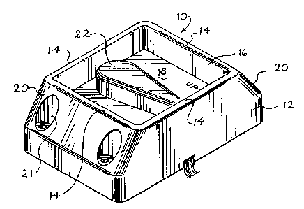
Figure 1 is a perspective view of an electrical switch that incorporates a
preferred embodiment of this invention.
Figure 2 is an exploded perspective view of the switch of Figure 1 from
below.
Figure 3 is a top view of the switch of Figure 1 showing the switch
actuator in three alternative positions.
Figure 4 is a side view of the switch of Figure 1.
Figure 5 is a bottom view of the switch of Figure 1 with selected
elements removed for clarity of illustration.
DETAILED DESCRIPTION OF THE
PRESENTLY PREFERRED EMBODIMENT
Turning now to the drawings, Figure 1 shows a perspective view of an
electric switch 10 that includes a rigid housing 12 and a switch actuator 22.
The rigid housing 12 includes four walls 14 that extend continuously
around a recess 16. The lower portion of the recess 16 is defined by a
recessed surface 18. As shown in Figure 1, two of the walls 14 include
sloped portions 20 that are shaped to deflect impacted objects. Openings 21
are provided for mounting fasteners (not shown).
As best shown in Figure 2, the actuator 22 includes a shaft 24 that is
mounted for pivotal motion in the housing 12 about an axis of rotation 26. A

CA 02286228 1999-10-06
WO 99144210 PCTIUS99/04320
3
magnet 34 is secured to the actuator above the surface 18, and a spring 36 is
disposed around the shaft 24. This spring 36 reacts against both the housing
12 and a protruding collar 23 carried by the shaft 24 to bias the actuator 22
to
the central position shown in Figure 1. A screw 25 secures the collar 23 to
the shaft 24 to hold the assembly together.
As shown in Figure 4, the actuator 22 is disposed completely within the
recess 16, and the walls 14 therefore protect the actuator 22 from impacting
objects. Furthermore, as shown in Figure 3, the axis 26 is positioned
peripherally in the recessed surface 18 and pivoting movement of the actuator
22 about the axis 26 is limited by the walls 14. In Figure 3, the dotted
outlines
22', 22" show the actuator 22 at the two extremes of travel, in which the end
of the actuator 22 is in contact with the respective walls 14, and the walls
14
restrain the actuator 22 against further pivotal movement. Thus, the walls 14
limit the pivoting range of travel of the actuator 22 and thereby protect the
actuator 22 and other components of the switch 10 from over-rotation by the
operator.
As best shown in Figure 2, first and second reed switches 30, 32 are
mounted in a lower portion of the housing 12. Each of the reed switches 30,
32 has a first contact in electrical communication with a common terminal 48,
as well as a second, switched contact, in contact with first and second
switched terminals 40, 42, respectively. In Figure 3 the solid line outline of
the actuator 22 shows the position of the actuator in a central position, in
which neither of the reed switches 30, 32 is activated. The dotted line
outline
22' shows the actuator in an upper position at an extreme of travel. In this
position the magnet 34 is aligned with the first reed switch 30, and the first
reed switch 30 is activated (closed in this example). Similarly, the dotted
line
outline 22" shows a lower position of the actuator in which the magnet 34 is
aligned with the second reed switch 32, and the second reed switch 32 is
activated (closed in this embodiment).

CA 02286228 1999-10-06
WO 99/44210 PCT/US99104320
4
As shown in Figure 2, the reed switches 30, 32 and associated diodes
31, 33 are mounted on an assembly plate 35 by rivets 37. A metallic
magnetic shunt 39 is mounted in the housing 12 beneath the assembly plate
35 to shield the reed switches 36, 32 from unintended activation when the
magnet 34 is in the central position. Preferably, the magnetic shunt 37 and
the assembly plate 35 with its associated components are potted in place in a
lower recess of the housing 12, using conventional potting materials. Figure
5 shows the assembly without potting materials, showing conductors 41
connected to respective ones of the terminals 40, 42, 48 by the rivets 37.
The electrical switch 10 is rugged and weather-proof. The rigid
housing 12 protects the actuator 22 against impacting objects as well as
against over-rotation. The reed switches 30, 32 are hermetically sealed, and
therefore weather-proof. By way of example, the housing 12 can be formed
of a fiber-reinforced thermoplastic material such as that sold under the trade
name VALOX 420.
Various modifications can be made to the switch 10 described above.
For example, the actuator can be mounted to slide rather than pivot with
respect to the housing, and the actuator can be fom~ed as push buttons, if
desired. Furthermore, the reed switches and magnet described above can be
replaced with one or more mechanical switches, as long as the mechanical
switches are properly sealed to provide the desired weather-proofness. It is
not essential in all embodiments that the walls extend continuously around
the recess, and if desired the walls can extend partly around at least three
sides of the recess. Similarly, one or more gaps can be formed in the walls.
Materials and proportions can all be changed as suitable for the intended
application.
As used herein, the term "activate" is intended broadly to encompass
both the opening of a normally closed switch and the closing of a normally
open switch.

CA 02286228 1999-10-06
WO 99/44210 PCT/US99/04320
The foregoing detailed description has discussed only a few of the
many forms that the present invention can take. For this reason, this detailed
description is intended as illustrative and not as limiting. It is only the
following claims, including all equivalents, that are intended to define the
5 scope of this invention.

Representative Drawing
A single figure which represents the drawing illustrating the invention.
Administrative Status

2024-08-01:As part of the Next Generation Patents (NGP) transition, the Canadian Patents Database (CPD) now contains a more detailed Event History, which replicates the Event Log of our new back-office solution.

Please note that "Inactive:" events refers to events no longer in use in our new back-office solution.

For a clearer understanding of the status of the application/patent presented on this page, the site Disclaimer , as well as the definitions for Patent , Event History , Maintenance Fee  and Payment History  should be consulted.

Event History

Description Date
Time Limit for Reversal Expired 2014-02-26
Letter Sent 2013-02-26
Inactive: IPC from MCD 2006-03-12
Inactive: Late MF processed 2005-04-05
Letter Sent 2005-02-28
Letter Sent 2004-12-06
Grant by Issuance 2003-04-22
Inactive: Cover page published 2003-04-21
Pre-grant 2002-12-18
Inactive: Final fee received 2002-12-18
Notice of Allowance is Issued 2002-06-28
Letter Sent 2002-06-28
Notice of Allowance is Issued 2002-06-28
Inactive: Approved for allowance (AFA) 2002-06-14
Amendment Received - Voluntary Amendment 2002-05-08
Inactive: S.30(2) Rules - Examiner requisition 2002-01-25
Letter Sent 2001-03-13
Reinstatement Requirements Deemed Compliant for All Abandonment Reasons 2001-02-28
Deemed Abandoned - Failure to Respond to Maintenance Fee Notice 2001-02-26
Inactive: Cover page published 1999-11-29
Inactive: IPC assigned 1999-11-23
Inactive: First IPC assigned 1999-11-23
Inactive: Acknowledgment of national entry - RFE 1999-11-10
Letter Sent 1999-11-10
Application Received - PCT 1999-11-08
All Requirements for Examination Determined Compliant 1999-10-06
Request for Examination Requirements Determined Compliant 1999-10-06
Application Published (Open to Public Inspection) 1999-09-02

Abandonment History

Abandonment Date Reason Reinstatement Date
2001-02-26

Maintenance Fee

The last payment was received on 2003-02-03

Note : If the full payment has not been received on or before the date indicated, a further fee may be required which may be one of the following

  • the reinstatement fee;
  • the late payment fee; or
  • additional fee to reverse deemed expiry.

Please refer to the CIPO Patent Fees web page to see all current fee amounts.

Owners on Record

Note: Records showing the ownership history in alphabetical order.

Current Owners on Record
INTELLITEC PRODUCTS LLC
Past Owners on Record
WILLIAM H. SLAVIK
Past Owners that do not appear in the "Owners on Record" listing will appear in other documentation within the application.
Documents

To view selected files, please enter reCAPTCHA code :


To view images, click a link in the Document Description column. To download the documents, select one or more checkboxes in the first column and then click the "Download Selected in PDF format (Zip Archive)" or the "Download Selected as Single PDF" button.

List of published and non-published patent-specific documents on the CPD .

If you have any difficulty accessing content, you can call the Client Service Centre at 1-866-997-1936 or send them an e-mail at CIPO Client Service Centre.


Document
Description 
Date
(yyyy-mm-dd) 
Number of pages   Size of Image (KB) 
Cover Page 2003-03-18 1 45
Description 1999-10-06 5 193
Claims 1999-10-06 3 94
Abstract 1999-10-06 1 59
Drawings 1999-10-06 3 103
Cover Page 1999-11-29 1 41
Representative drawing 2002-06-17 1 18
Claims 2002-05-13 2 75
Representative drawing 1999-11-29 1 8
Notice of National Entry 1999-11-10 1 202
Courtesy - Certificate of registration (related document(s)) 1999-11-10 1 115
Reminder of maintenance fee due 2000-10-30 1 110
Courtesy - Abandonment Letter (Maintenance Fee) 2001-03-13 1 182
Notice of Reinstatement 2001-03-13 1 169
Commissioner's Notice - Application Found Allowable 2002-06-28 1 164
Late Payment Acknowledgement 2005-04-18 1 165
Maintenance Fee Notice 2005-04-18 1 172
Maintenance Fee Notice 2013-04-09 1 171
Correspondence 2002-12-18 1 33
PCT 1999-10-06 2 87
Fees 2001-02-28 1 57
Fees 2005-04-05 1 34