Sélection de la langue

Search

Sommaire du brevet 2286228 

Énoncé de désistement de responsabilité concernant l'information provenant de tiers

Une partie des informations de ce site Web a été fournie par des sources externes. Le gouvernement du Canada n'assume aucune responsabilité concernant la précision, l'actualité ou la fiabilité des informations fournies par les sources externes. Les utilisateurs qui désirent employer cette information devraient consulter directement la source des informations. Le contenu fourni par les sources externes n'est pas assujetti aux exigences sur les langues officielles, la protection des renseignements personnels et l'accessibilité.

Disponibilité de l'Abrégé et des Revendications

L'apparition de différences dans le texte et l'image des Revendications et de l'Abrégé dépend du moment auquel le document est publié. Les textes des Revendications et de l'Abrégé sont affichés :

  • lorsque la demande peut être examinée par le public;
  • lorsque le brevet est émis (délivrance).
(12) Brevet: (11) CA 2286228
(54) Titre français: INTERRUPTEUR ELECTRIQUE
(54) Titre anglais: ELECTRICAL SWITCH
Statut: Périmé et au-delà du délai pour l’annulation
Données bibliographiques
(51) Classification internationale des brevets (CIB):
  • H01H 9/00 (2006.01)
  • H01H 3/12 (2006.01)
  • H01H 9/20 (2006.01)
  • H01H 36/00 (2006.01)
(72) Inventeurs :
  • SLAVIK, WILLIAM H. (Etats-Unis d'Amérique)
(73) Titulaires :
  • INTELLITEC PRODUCTS LLC
(71) Demandeurs :
  • INTELLITEC PRODUCTS LLC (Etats-Unis d'Amérique)
(74) Agent: CASSAN MACLEAN
(74) Co-agent:
(45) Délivré: 2003-04-22
(86) Date de dépôt PCT: 1999-02-26
(87) Mise à la disponibilité du public: 1999-09-02
Requête d'examen: 1999-10-06
Licence disponible: S.O.
Cédé au domaine public: S.O.
(25) Langue des documents déposés: Anglais

Traité de coopération en matière de brevets (PCT): Oui
(86) Numéro de la demande PCT: PCT/US1999/004320
(87) Numéro de publication internationale PCT: WO 1999044210
(85) Entrée nationale: 1999-10-06

(30) Données de priorité de la demande:
Numéro de la demande Pays / territoire Date
09/031,030 (Etats-Unis d'Amérique) 1998-02-26

Abrégés

Abrégé français

L'invention concerne un interrupteur électrique qui comprend un boîtier composé de parois s'étendant de manière continue autour d'un évidement. Un actionneur d'interrupteur est monté pivotant dans l'évidement situé dans le boîtier et protégé par les parois. Un premier et un second interrupteur à tiges sont montés dans le boîtier. Un aimant est monté sur l'actionneur d'interrupteur et peut pivoter entre une première position, dans laquelle l'aimant actionne le premier interrupteur à tiges, et une seconde position, dans laquelle l'aimant actionne le second interrupteur à tiges.


Abrégé anglais


An electrical switch (10) includes a housing (12) having walls (14) extending
continuously around a recess (16). A switch actuator (22) is pivotally mounted
in the housing (12) in the recess (16) and protected by the walls (14). First
and second reed switches (30, 32) are mounted in the housing (10), and a
magnet (34) is mounted to the switch actuator (22) and is pivotable between a
first position, in which the magnet (34) activates the first reed switch (30),
and a second position, in which the magnet (34) activates the second reed
switch (32).

Revendications

Note : Les revendications sont présentées dans la langue officielle dans laquelle elles ont été soumises.


1. An electrical switch comprising:
a housing comprising a recessed surface and at least one wall disposed at
least partly around the recessed surface, the recessed surface and the at
least one wall
cooperating to form a recess in an outer portion of the housing;
a switch mounted in the housing; and
a switch actuator coupled with the switch and mounted in the recess to
pivot about an axis oriented substantially perpendicular to the recessed
surface, said
switch actuator comprising an operating lever that pivots between a first
extreme of
travel, at which the operating lever contacts a first portion of the at least
one wall, and a
second extreme of travel, at which the operating lever contacts a second
portion of the
at least one wall; said operating lever manually accessible in the recess from
outside
the housing; said first and second portions of the at least one wall limiting
pivoting
movement of the operating lever and protecting the switch against over-
rotation.
2. The invention of claim 1 wherein the switch comprises first and second
reed switches, and wherein the actuator comprises a magnet.
3. The invention of claim 2 wherein the magnet is positioned in the actuator
such that the magnet activates the first reed switch when the operating lever
is in the
first extreme of travel, and the magnet activates the second reed switch when
the
operating lever is in the second extreme of travel.
4. The invention of claim 3 wherein the at least one wall is at least in part
outwardly sloped for deflecting objects that may impact the housing.
5. The invention of claim 3 further comprising a spring reacting between the
switch actuator and the housing to bias the switch actuator to a third
position, in which
the magnet activates neither the first reed switch nor the second reed switch.
6. The invention of claim 1 wherein the axis is positioned peripherally in the
recessed surface near the at least one wall.

7. The invention of claim 1 wherein the at least one wall extends beyond the
switch actuator such that the switch actuator is completely recessed in the
housing.
8. The invention of claim 1 wherein the housing comprises a plurality of
openings configured to receive mounting fasteners, said openings positioned on
outer
surfaces of the at least one wall.
9. The invention of claim 1 wherein the housing comprises a fiber-reinforced
thermoplastic material.

Description

Note : Les descriptions sont présentées dans la langue officielle dans laquelle elles ont été soumises.

CA 02286228 1999-10-06
WO 99/44210 PCT/US99/04320
1
Electrical Switch
BACKGROUND
This invention relates to an electrical switch that is weatherproof and
welt protected against impacts and operator abuse.
Electrical switches are commonly used as control switches in outdoor
applications. For example, a delivery truck may carry a hydraulically-powered
lift gate, and electrical switches are typically provided on the outside of
the
delivery trucks to allow the driver to control the lift gate. Such electrical
switches must operate reliably in a harsh environment. Any switch failure can
cause such delivery truck to be stranded, particularly if the switch fails
with
the lift gate in the lowered position.
In the past, lift gate switches of this type have proven insufficiently
rugged in use. Such switches are exposed at an exterior surface of the truck,
and they are subjected to occasional impacts from moving objects.
Furthermore, operator abuse may disable a switch if it is not properly
designed. Weather-proofness is another important characteristic of such
switches.
SUMMARY
The present invention is directed to an improved electrical switch that
meets the operational objectives discussed above. The switch of this
invention is defined by the following claims, and nothing in this summary
should be taken as a limitation on those claims.
By way of introduction, it can be stated that the electrical switch
described below pivotably mounts a switch actuator in a recess defined by a
*rB

CA 02286228 1999-10-06
WO 99/44210 PCT/US99/04320
2
rigid housing. The walls of the housing around the recess protect the switch
actuator from impact with moving objects, and the walls around the recess
also limit the range of travel of the actuator, thereby protecting the
actuator
and the switch components frorti over travel. In the preferred embodiment
described below, the switch actuator carries a magnet, and the housing
carries first and second reed switches. The switch actuator is pivotable
between a first position, in which the magnet activates the first reed switch,
and a second position, in which the magnet activates the second reed switch.
BRIEF DESCRIPTION OF THE DRAWINGS
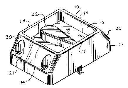
Figure 1 is a perspective view of an electrical switch that incorporates a
preferred embodiment of this invention.
Figure 2 is an exploded perspective view of the switch of Figure 1 from
below.
Figure 3 is a top view of the switch of Figure 1 showing the switch
actuator in three alternative positions.
Figure 4 is a side view of the switch of Figure 1.
Figure 5 is a bottom view of the switch of Figure 1 with selected
elements removed for clarity of illustration.
DETAILED DESCRIPTION OF THE
PRESENTLY PREFERRED EMBODIMENT
Turning now to the drawings, Figure 1 shows a perspective view of an
electric switch 10 that includes a rigid housing 12 and a switch actuator 22.
The rigid housing 12 includes four walls 14 that extend continuously
around a recess 16. The lower portion of the recess 16 is defined by a
recessed surface 18. As shown in Figure 1, two of the walls 14 include
sloped portions 20 that are shaped to deflect impacted objects. Openings 21
are provided for mounting fasteners (not shown).
As best shown in Figure 2, the actuator 22 includes a shaft 24 that is
mounted for pivotal motion in the housing 12 about an axis of rotation 26. A

CA 02286228 1999-10-06
WO 99144210 PCTIUS99/04320
3
magnet 34 is secured to the actuator above the surface 18, and a spring 36 is
disposed around the shaft 24. This spring 36 reacts against both the housing
12 and a protruding collar 23 carried by the shaft 24 to bias the actuator 22
to
the central position shown in Figure 1. A screw 25 secures the collar 23 to
the shaft 24 to hold the assembly together.
As shown in Figure 4, the actuator 22 is disposed completely within the
recess 16, and the walls 14 therefore protect the actuator 22 from impacting
objects. Furthermore, as shown in Figure 3, the axis 26 is positioned
peripherally in the recessed surface 18 and pivoting movement of the actuator
22 about the axis 26 is limited by the walls 14. In Figure 3, the dotted
outlines
22', 22" show the actuator 22 at the two extremes of travel, in which the end
of the actuator 22 is in contact with the respective walls 14, and the walls
14
restrain the actuator 22 against further pivotal movement. Thus, the walls 14
limit the pivoting range of travel of the actuator 22 and thereby protect the
actuator 22 and other components of the switch 10 from over-rotation by the
operator.
As best shown in Figure 2, first and second reed switches 30, 32 are
mounted in a lower portion of the housing 12. Each of the reed switches 30,
32 has a first contact in electrical communication with a common terminal 48,
as well as a second, switched contact, in contact with first and second
switched terminals 40, 42, respectively. In Figure 3 the solid line outline of
the actuator 22 shows the position of the actuator in a central position, in
which neither of the reed switches 30, 32 is activated. The dotted line
outline
22' shows the actuator in an upper position at an extreme of travel. In this
position the magnet 34 is aligned with the first reed switch 30, and the first
reed switch 30 is activated (closed in this example). Similarly, the dotted
line
outline 22" shows a lower position of the actuator in which the magnet 34 is
aligned with the second reed switch 32, and the second reed switch 32 is
activated (closed in this embodiment).

CA 02286228 1999-10-06
WO 99/44210 PCT/US99104320
4
As shown in Figure 2, the reed switches 30, 32 and associated diodes
31, 33 are mounted on an assembly plate 35 by rivets 37. A metallic
magnetic shunt 39 is mounted in the housing 12 beneath the assembly plate
35 to shield the reed switches 36, 32 from unintended activation when the
magnet 34 is in the central position. Preferably, the magnetic shunt 37 and
the assembly plate 35 with its associated components are potted in place in a
lower recess of the housing 12, using conventional potting materials. Figure
5 shows the assembly without potting materials, showing conductors 41
connected to respective ones of the terminals 40, 42, 48 by the rivets 37.
The electrical switch 10 is rugged and weather-proof. The rigid
housing 12 protects the actuator 22 against impacting objects as well as
against over-rotation. The reed switches 30, 32 are hermetically sealed, and
therefore weather-proof. By way of example, the housing 12 can be formed
of a fiber-reinforced thermoplastic material such as that sold under the trade
name VALOX 420.
Various modifications can be made to the switch 10 described above.
For example, the actuator can be mounted to slide rather than pivot with
respect to the housing, and the actuator can be fom~ed as push buttons, if
desired. Furthermore, the reed switches and magnet described above can be
replaced with one or more mechanical switches, as long as the mechanical
switches are properly sealed to provide the desired weather-proofness. It is
not essential in all embodiments that the walls extend continuously around
the recess, and if desired the walls can extend partly around at least three
sides of the recess. Similarly, one or more gaps can be formed in the walls.
Materials and proportions can all be changed as suitable for the intended
application.
As used herein, the term "activate" is intended broadly to encompass
both the opening of a normally closed switch and the closing of a normally
open switch.

CA 02286228 1999-10-06
WO 99/44210 PCT/US99/04320
The foregoing detailed description has discussed only a few of the
many forms that the present invention can take. For this reason, this detailed
description is intended as illustrative and not as limiting. It is only the
following claims, including all equivalents, that are intended to define the
5 scope of this invention.

Dessin représentatif
Une figure unique qui représente un dessin illustrant l'invention.
États administratifs

2024-08-01 : Dans le cadre de la transition vers les Brevets de nouvelle génération (BNG), la base de données sur les brevets canadiens (BDBC) contient désormais un Historique d'événement plus détaillé, qui reproduit le Journal des événements de notre nouvelle solution interne.

Veuillez noter que les événements débutant par « Inactive : » se réfèrent à des événements qui ne sont plus utilisés dans notre nouvelle solution interne.

Pour une meilleure compréhension de l'état de la demande ou brevet qui figure sur cette page, la rubrique Mise en garde , et les descriptions de Brevet , Historique d'événement , Taxes périodiques et Historique des paiements devraient être consultées.

Historique d'événement

Description Date
Le délai pour l'annulation est expiré 2014-02-26
Lettre envoyée 2013-02-26
Inactive : CIB de MCD 2006-03-12
Inactive : TME en retard traitée 2005-04-05
Lettre envoyée 2005-02-28
Lettre envoyée 2004-12-06
Accordé par délivrance 2003-04-22
Inactive : Page couverture publiée 2003-04-21
Préoctroi 2002-12-18
Inactive : Taxe finale reçue 2002-12-18
Un avis d'acceptation est envoyé 2002-06-28
Lettre envoyée 2002-06-28
Un avis d'acceptation est envoyé 2002-06-28
Inactive : Approuvée aux fins d'acceptation (AFA) 2002-06-14
Modification reçue - modification volontaire 2002-05-08
Inactive : Dem. de l'examinateur par.30(2) Règles 2002-01-25
Lettre envoyée 2001-03-13
Exigences de rétablissement - réputé conforme pour tous les motifs d'abandon 2001-02-28
Réputée abandonnée - omission de répondre à un avis sur les taxes pour le maintien en état 2001-02-26
Inactive : Page couverture publiée 1999-11-29
Inactive : CIB attribuée 1999-11-23
Inactive : CIB en 1re position 1999-11-23
Inactive : Acc. récept. de l'entrée phase nat. - RE 1999-11-10
Lettre envoyée 1999-11-10
Demande reçue - PCT 1999-11-08
Toutes les exigences pour l'examen - jugée conforme 1999-10-06
Exigences pour une requête d'examen - jugée conforme 1999-10-06
Demande publiée (accessible au public) 1999-09-02

Historique d'abandonnement

Date d'abandonnement Raison Date de rétablissement
2001-02-26

Taxes périodiques

Le dernier paiement a été reçu le 2003-02-03

Avis : Si le paiement en totalité n'a pas été reçu au plus tard à la date indiquée, une taxe supplémentaire peut être imposée, soit une des taxes suivantes :

  • taxe de rétablissement ;
  • taxe pour paiement en souffrance ; ou
  • taxe additionnelle pour le renversement d'une péremption réputée.

Veuillez vous référer à la page web des taxes sur les brevets de l'OPIC pour voir tous les montants actuels des taxes.

Titulaires au dossier

Les titulaires actuels et antérieures au dossier sont affichés en ordre alphabétique.

Titulaires actuels au dossier
INTELLITEC PRODUCTS LLC
Titulaires antérieures au dossier
WILLIAM H. SLAVIK
Les propriétaires antérieurs qui ne figurent pas dans la liste des « Propriétaires au dossier » apparaîtront dans d'autres documents au dossier.
Documents

Pour visionner les fichiers sélectionnés, entrer le code reCAPTCHA :


Pour visualiser une image, cliquer sur un lien dans la colonne description du document. Pour télécharger l'image (les images), cliquer l'une ou plusieurs cases à cocher dans la première colonne et ensuite cliquer sur le bouton "Télécharger sélection en format PDF (archive Zip)" ou le bouton "Télécharger sélection (en un fichier PDF fusionné)".

Liste des documents de brevet publiés et non publiés sur la BDBC .

Si vous avez des difficultés à accéder au contenu, veuillez communiquer avec le Centre de services à la clientèle au 1-866-997-1936, ou envoyer un courriel au Centre de service à la clientèle de l'OPIC.


Description du
Document 
Date
(aaaa-mm-jj) 
Nombre de pages   Taille de l'image (Ko) 
Page couverture 2003-03-18 1 45
Description 1999-10-06 5 193
Revendications 1999-10-06 3 94
Abrégé 1999-10-06 1 59
Dessins 1999-10-06 3 103
Page couverture 1999-11-29 1 41
Dessin représentatif 2002-06-17 1 18
Revendications 2002-05-13 2 75
Dessin représentatif 1999-11-29 1 8
Avis d'entree dans la phase nationale 1999-11-10 1 202
Courtoisie - Certificat d'enregistrement (document(s) connexe(s)) 1999-11-10 1 115
Rappel de taxe de maintien due 2000-10-30 1 110
Courtoisie - Lettre d'abandon (taxe de maintien en état) 2001-03-13 1 182
Avis de retablissement 2001-03-13 1 169
Avis du commissaire - Demande jugée acceptable 2002-06-28 1 164
Quittance d'un paiement en retard 2005-04-18 1 165
Avis concernant la taxe de maintien 2005-04-18 1 172
Avis concernant la taxe de maintien 2013-04-09 1 171
Correspondance 2002-12-18 1 33
PCT 1999-10-06 2 87
Taxes 2001-02-28 1 57
Taxes 2005-04-05 1 34