Language selection

Search

Patent 2286404 Summary

Third-party information liability

Some of the information on this Web page has been provided by external sources. The Government of Canada is not responsible for the accuracy, reliability or currency of the information supplied by external sources. Users wishing to rely upon this information should consult directly with the source of the information. Content provided by external sources is not subject to official languages, privacy and accessibility requirements.

Claims and Abstract availability

Any discrepancies in the text and image of the Claims and Abstract are due to differing posting times. Text of the Claims and Abstract are posted:

  • At the time the application is open to public inspection;
  • At the time of issue of the patent (grant).
(12) Patent: (11) CA 2286404
(54) English Title: TWO-POSITION SCREWDRIVER
(54) French Title: TOURNEVIS A DEUX POSITIONS
Status: Deemed expired
Bibliographic Data
(51) International Patent Classification (IPC):
  • B25B 21/00 (2006.01)
  • B25F 5/02 (2006.01)
(72) Inventors :
  • ALSRUHE, WALLIS (United States of America)
(73) Owners :
  • BLACK & DECKER INC. (United States of America)
(71) Applicants :
  • BLACK & DECKER INC. (United States of America)
(74) Agent: GOWLING WLG (CANADA) LLP
(74) Associate agent:
(45) Issued: 2008-12-23
(22) Filed Date: 1999-10-14
(41) Open to Public Inspection: 2000-04-16
Examination requested: 2003-12-23
Availability of licence: N/A
(25) Language of filing: English

Patent Cooperation Treaty (PCT): No

(30) Application Priority Data:
Application No. Country/Territory Date
09/174,145 United States of America 1998-10-16

Abstracts

English Abstract

A two-position tool has a pair of housing members rotatable with respect to one another. A locking mechanism is coupled with one of the housing members to lock the two housing members in a plurality of positions with respect to one another. In a first position, the axes of the housing members are substantially colinear with one another and in a second position, the axes are angled with respect to one another. The locking mechanism includes an activation member and a pin coupled with the activation member. A detent member is coupled with one of the housing members. The detent member has a plurality of detents to receive the movable pin to lock the housing member in the plurality of positions.


French Abstract

Un outil à deux positions est muni d'une paire d'éléments de logement pouvant tourner l'un par rapport à l'autre. Un mécanisme de verrouillage est couplé à l'un des éléments de logement pour les verrouiller dans plusieurs positions l'un par rapport à l'autre. dans une première position, les axes des éléments de logement sont essentiellement colinéaires l'un par rapport à l'autre et, dans une seconde position, les axes sont angulaires l'un par rapport à l'autre. Le mécanisme de verrouillage inclut un élément d'activation et une tige couplée à l'élément d'activation. Un élément déclencheur est couplé à l'un des éléments de logement. L'élément déclencheur est doté de plusieurs détentes pour recevoir la tige mobile pour verrouiller les éléments de logement dans plusieurs positions.

Claims

Note: Claims are shown in the official language in which they were submitted.


Claims

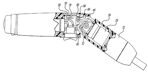
1. A tool operable in at least two positions, comprising:
two housing members, each defining an axis;

a pivot coupled with said two housing members for pivotally coupling
said two housing members with one another;

a lock mechanism coupled with one of said housing members for locking
said two housing members in a plurality of positions with respect to one
another
such that in a first position said axes are substantially colinear and in a
second
position said axes are angled with respect to one another and said axes are in

the same plane during pivoting of said housing members;

said lock mechanism including an activation member;
a movable pin coupled with said activation member;

a detent member coupled with one of said housing members, said
detent member having a plurality of detents for receiving said movable pin for

locking said housing members in said plurality of positions and a cam surface
on said detent member for moving said pin.


2. The tool according to claim 1, wherein a guide mechanism directs
the movement of said movable pin.


3. The tool according to claim 2, wherein said guide mechanism
enables movement of said pin in a plurality of directions.


4. The tool according to claim 3, wherein said guide mechanism
includes a member extending from said activation member having a slot for
receiving said pin and enabling movement of said pin in said slot.


9


5. The tool according to claim 4, wherein said guide mechanism
includes at least one channel on one of said housing members for guiding
movement of said pin.

6. The tool according to claim 1, wherein a biasing member is
coupled with said activation member for applying a force on said pin for
actively
maintaining said pin in said detents.

7. The tool according to claim 1, wherein said activation member
being movable and upon movement of said activation member, said pin being
withdrawn from said detent for enabling pivoting of said housing members with
respect to one another.

8. A multi-position tool comprising:
two housing members;

a pivot coupling said two housing members with one another for
enabling said two housing members to pivot with respect to one another;

at least two detents on one of said housing members;

a pin on the other of said housing members, said pin being movable in
two directions during positioning of said tool, one direction being
substantially
vertical and one direction being substantially horizontal, for being received
in
said at least two detents for maintaining said housing members in at least two
positions with respect to one another.

9. The multi-position tool according to claim 8, wherein a biasing
member being coupled with one of said housing members for applying force on
said pin for actively maintaining said pin in said detents.


10. The multi-position tool according to claim 9, wherein a guide
member being coupled with one of said housing members for guiding said pin
in a first direction.

11. The multi-position tool according to claim 10, wherein a second
guide member being on the other housing member for guiding said pin in a
second direction.

12. The multi-position tool according to claim 8, wherein an activation
member is coupled with said pin for moving said pin in and out of said
detents.
13. A multi-position tool comprising:

a pair of housing members pivotal in the same plane with respect to one
another, one of said housing members having at least two detents and a cam
surface;

a pin on the other housing member being received by said detents, said
pin being movable on said cam surface and biased such that as said pin moves
out of one detent, said housing members may be pivoted with respect to one
another and said biased pin being forced into said other detents for
maintaining
a second position on said tool.

14. The multi-position tool according to claim 13, wherein a guide
member being coupled with one of said housing members for guiding said pin
in a first direction.

15. The multi-position tool according to claim 14, wherein a second
guide member being on the other housing member for guiding said pin in a
second direction.

11


16. The multi-position tool according to claim 15, wherein a guide
mechanism including at least one channel on one of said housing members for
guiding movement of said pin.

17. The multi-position tool according to claim 14, wherein said guide
mechanism including a member extending from an activation member having a
slot for receiving said pin and enabling movement of said pin in said slot.

18. The multi-position tool according to claim 13, wherein an
activation member being coupled with said pin for moving said pin in and out
of
said detents.

19. The multi-position tool according to claim 13, wherein a biasing
member being coupled with an activation member for applying a force on said
pin for maintaining said pin in said detents.

20. A power tool comprising:

two housing members pivotally coupling with one another;
a power source coupled with one of said housing members;

a motor coupled with said power source and the other of said housing
members, an output coupled with said motor;

a switch coupled with said power source and motor for energizing and
de-energizing said motor for rotating said output, said switch positioned on
said
housing member including said power source;

a lock coupled with said housing member including said power source
for locking said two housing members in a plurality of positions with respect
to
one another such that in a first position axes of said housing members are
12


substantially colinear and in a second position, said axes are angled with
respect to one another; and

an activation member for actuating said locking member, said actuation
member positioned on the same housing member as said switch such that said
actuation member and switch oppose one another on said housing member
and are movable by a single hand of the user for pivoting said housing
members with respect to one another.

21. The power tool according to Claim 20, wherein said activation
member being slidable and said switch being pivotable.

22. The power tool according to Claim 20, wherein when said
activation member is in a retracted position, said housing members are
movable with respect to one another upon sudden movement of the
screwdriver by the user.

23. The power tool according to Claim 20, wherein said activation
member and switch are ergonomically positioned with respect to one another
for operation by the user's thumb and fingers of a single hand.

24. The power tool according to Claim 22 wherein said activation
member being spring biased to return to its original position.

25. The power tool according to Claim 20, wherein said housing
members being enabled to pivot with respect to one another during operation of
said motor.

26. The power tool according to Claim 25, wherein said pivoting
occurring while the axes move from a colinear position to an angled position.

13


27. The power tool according to Claim 20, wherein a battery is in said
power source housing member and said motor is in the other said housing
member.

28. A power tool comprising:

two housing members pivotally coupling with one another;
a power source coupled with one of said housing members;

a motor coupled with said power source and one of said housing
members, an output coupled with said motor;

a switch coupled with said power source and motor for energizing and
de-energizing said motor for rotating said output, said switch positioned on
said
housing member including said power source, and said switch positioned
immediately adjacent said pivot;

a lock coupled with one of said housing members for locking said two
housing members in a plurality of positions with respect to one another such
that in a first position axes of said housing members are substantially
colinear
and in a second position, said axes are angled with respect to one another;
and

an activation member for actuating said locking member, said actuation
member positioned on one of said housing members, said actuation member is
movable by the user for pivoting said housing members with respect to one
another.

29. A power tool comprising:

two housing members pivotally coupling with one another;
a power source coupled with one of said housing members;
14


a motor coupled with said power source and one of said housing
members, an output coupled with said motor;

a switch coupled with said power source and motor for energizing and
de-energizing said motor for rotating said output, said switch positioned on
one
of said housing members;

a lock coupled with one of said housing members for locking said two
housing members in a plurality of positions with respect to one another such
that in a first position axes of said housing members are substantially
colinear
and in a second position, said axes are angled with respect to one another and
said axes are in the same plane during pivoting of said housing members, said
lock mechanism including a latch member for positively locking said two
housing members with respect to one another in each of said plurality of
positions; and

an activation member for actuating said locking member, said actuation
member positioned on one of said housing members, enabling the user to pivot
said housing members with respect to one another.

30. A power tool comprising:

two housing members pivotally coupling with one another;
a power source coupled with one of said housing members;

a motor coupled with said power source and one of said housing
members, an output coupled with said motor;

a switch coupled with said power source and motor for energizing and
de-energizing said motor for rotating said output, said switch positioned on
one
of said housing members;


a lock coupled with one of said housing members for locking said two
housing members in a plurality of positions with respect to one another such
that in a first position axes of said housing members are substantially
colinear
and in a second position, said axes are angled with respect to one another,
said lock mechanism including a latch member for positively locking said two
housing members with respect to one another in each of said plurality of
positions; and

an activation member for actuating said locking member, said actuation
member positioned on one of said housing members, such that the activation
member is movable by a single hand of the user to enable pivoting of said
housing members with respect to one another by the single hand of the user.

16

Description

Note: Descriptions are shown in the official language in which they were submitted.


CA 02286404 1999-10-14

TWO-POSITION SCREWDRIVER
Background of the Invention

The present invention relates to hand held power tools and, more
particularly, to hand held power tools which move to a plurality of
positions.

Hand held power tools are utilized by general consumers as well as
professional tradesmen. Hand held power tools have replaced the
burdensome turning and rotation of manual hand tools. Specifically, in the

screwdriver field, hand held power screwdrivers have become extremely
popular. Hand held power screwdrivers ordinarily have the rotatable spindle
co-axial with the screwdriver housing. When a drill motor is utilized with a
screwdriver bit, the spindle is ordinarily at a 90 angle with respect to the
drill motor handle.

When utilizing a stick type of power screwdriver, sometimes it is
desirable to utilize the power screwdriver at various angles with respect to
the workpiece. However, while the screwdriver is positioned at the varied
angle, it does not always enable the user to have an adequate grip on the
screwdriver to provide a desired force.

Accordingly, various types of positionable tools have served this
function. Positionable tools ordinarily have a first position where the
spindle is co-axial with the tool housing and a second position where the
spindle is angled with respect to the tool housing. Thus, the user, when

necessary, angles the spindle with respect to the remaining portion of the
housing to enable a better grip on the power tool. The better positioning of
the spindle enables the user to provide a desired force onto the fastener.


CA 02286404 2007-11-29

Several types of positionable tools exist in the art. While these tools
appear to be satisfactory for their intended purpose, designers strive to
improve
the art.

Summary of the Invention

The present invention provides the art with a positionable hand held
power tool. The power tool is provided with a mechanism to actively retain the
housing portions in a plurality of positions with respect to one another. The
present invention provides an active bias member to lock the housing portions
with respect to one another.

In accordance with a first aspect of the invention, a tool operated in a
plurality of positions comprises two housing members each defining an axis. A
pivot couples the two housing members for pivotal movement with respect to
one another. A lock mechanism is coupled with one of the housing members
for locking the two housing members in a plurality of positions with respect
to

one another. In a first position, the axes of the housing members are
generally
colinear. In a second position, the axes are angled with respect to one
another
and the axes are in the same plane during pivoting of the housing members.
The lock mechanism includes an activation member. A movable pin is coupled
with the activation member. A detent member is coupled with one of the

housing members. The detent member includes a plurality of detents for
receiving a movable pin to lock the housing members in one of the plurality of
positions. A guide mechanism is also present which directs the movement of
the movable pin. The guide mechanism enables movement of the pin in a
plurality of directions. The guide mechanism includes a member extending from

the activation member which includes a slot to receive the pin and enable
2


CA 02286404 1999-10-14

movement of the pin in the slot. The guide mechanism also includes at
least one channel on one of the housing members for guiding movement of
the pin. A biasing member is coupled with the activation member to apply
a force on the pin to maintain the pin in the detents. The activation

member is moved to remove the pin from a detent to enable pivoting of the
housing members with respect to one another. Also the detent member
includes a cam surface to move the pin in a desired direction.

In accordance with a second aspect of the invention, a two-position
tool is disclosed comprising two housing members with a pivot coupling the
two members together with one another to enable pivoting of the two

members with respect to one another. At least two detents are on one of
the housing members. A pin is on the other of the housing members and is
movable in two directions to be received in at least two detents to maintain
the housing members in at least two positions with respect to one another.

A biasing member applies a force on the pin to actively maintain the pin in
the detents. A guide member is coupled with one of the housing members
to guide the pin in a first direction. A second guide member is on the other
housing to guide the pin in a second direction. An activation member is
coupled with the pin to move the pin in and out of the detents.

In accordance with a third aspect of the invention, a two-position
tool comprises a pair of housing members pivotal with respect to one
another. One of the housing members has at least two detents. A pin is
on the other housing member to be received by the detents. The pin is
movable and biased such that as the pin moves out of one detent, the

housing members may be pivotal with respect to one another and the
-3 -


CA 02286404 2007-11-29

biased pin is forced into the other detent to maintain a tool in a second
position.
A guide member is coupled with one of the housing members to guide the pin
in a first direction. A second guide member is on the other housing member to
guide the pin in a second direction. An activation member is coupled with the

pin to move the pin in and out of the detents. The guide mechanism includes a
member extending from the activation member which includes a slot to receive
the pin. The pin is movable in the slot. The second guide members includes at
least one channel in the housing member to guide movement of the pin. A
biasing member is coupled with the activation member to apply a force on the

pin to actively maintain the pin in the detents. The detent member also
includes
a cam surface to move the pin.

From the following detailed description, taken in conjunction with the
accompanying drawings and subjoined claims, other objects, features and
advantages of the present invention will become more fully apparent to one
skilled in the art.

Brief Description of the Drawinas

Figure 1 is a pian view of a two-position hand tool in accordance with the
present invention.

Figure 2 is a plan view of the tool of Figure 1 in a second position.

Figure 3 shows the housing members opened up to provide an inside
plan view of the housing.

Figure 4 is a partial cross-section view of the housing of Figure 1.

Figure 5 is a partial cross-section view like Figure 4 during rotation of the
housing members with respect to one another.

4


CA 02286404 2007-11-29

Figure 6 is a view like Figure 5 in a second position.
Detailed Description of the Preferred Embodiment

Turning to the figures, a hand held power tool is illustrated and
designated with the reference numeral 10. The power tool 10 includes a first
housing member 12 and a second housing member 14. The housing members

12 and 14 are pivotal with respect to one another. The housing portion 12
includes a motor 18 driving a transmission 20 which, in turn, drives the
output
spindle 22. The second housing member 14 includes a cavity 24 to receive a
battery 26. A switch 28 is electrically coupled with the battery 26 and the
motor
18 to drive the spindle in a forward and reverse direction.

The first housing member 12 includes a pair of clam shell halves 30
which are coupled with one another to form the housing member 12. The
housing member 12 includes a rear portion 40 which opposes the spindle 22.
The rear portion 40 includes an aperture 42 to receive a pivot 44 from the

second housing member 14. Also, the rear portion includes a pair of detents 46
and 48 separated by a cam surface portion 50. The detents 46 and 48 are on
the outer arcuate periphery of the rear portion 40. Also, the rear portion 40
includes a second aperture 52 to enable electrical wires, which extend to the
motor, to pass into the second housing member 14.

The second housing member 14 includes a pair of clam shell housing
halves 60 and 62. The housing halves 60 and 62 define apertures 64, 66 and
68. Aperture 66 receives the motor forward and reverse switch 28. The
aperture 64 receives an activating member 70. Aperture 68 receives
5


CA 02286404 1999-10-14

the rear portion 40 of the first housing member 12. The housing portion 14
also includes a cut-out portion 72 which enables the first housing portion
12 to rotate into the cut-out portion 72.

The activation member 70 is slidable in a channel 74 in the housing
halves 60 and 62. The activation member 70 has an extending member 78
which receives a biasing member 80. One end of the biasing member 80
rests against an abutting wall 82 in the housing member 14. The biasing
member 80 provides an active force on the activation member 70. The
activation member 70 also includes a pair of extending fingers 84 and 86.

1 o The fingers 84 and 86 include oblong slots 88. A pin 90 is received within
the slots 88. The slots 88 enable the pin to move within the slots in a first
direction as the activation member 70 is slid along channel 74. A pair of
guide channels 94 and 96 are formed on the interior surfaces of the
housing halves 60 and 62. The guide channels 94 and 96 each receive an

end of the pin 90. The guide channels 94 and 96 enable the pin to slide
within the channels 94 and 96 in a second direction as the activation
member 70 is moved in the channel 74.

Turning to Figures 3-6, a better understanding of the activation
member 70 will be described. As seen in Figure 3, the pin 90 is actively
biased in detent 46. The pin locks the housing members in a first position

with respect to one another. The activation member 70 is then moved
along channels 74 against the biasing force of spring 80. As this occurs,
the pin 90 is moved along channels 94 and 96 of the housing halves 60
and 62. In order to move the housing members 12 and 14 with respect to

one another, the housing members 12 and 14 are pivoted with respect to
-6-


CA 02286404 1999-10-14

one another. When releasing the force on the actuation member 70, the
biasing spring exerts a force which acts on the pin 90, forcing it against the
surface 50. As the end of the cam surface 50 passes the pin 90, the
biasing spring 80 actively forces the pin 90 into detent 48 to lock the

motion. Thus, the housing members 12 and 14 are locked in a second
position with respect to one another. While two detents are illustrated in
the periphery of the housing member 12, more detents could be added to
lock the housing members in additional positions with respect to one
another.

Turning to Figures 1 and 2, the hollow cylindrical housing member
14 of screwdriver 10 includes switch 28 and activation member 70
oppositely opposed on housing member 14. These members are positioned
approximately one hundred eighty (180 ) degrees apart on the cylindrical
housing member 14. Thus, the user may easily use one hand to operate

the activation member 70 with his thumb while operating the pivot switch
28 with his fingers. The user may use his index and middle fingers or just
one of the fingers to operate the pivot switch 28 in the forward and reverse
directions. The user's thumb would be on the activation member 70 sliding
it in a forward and backward manner. This provides a very ergonomical

design such that the screwdriver 10 is easily manipulated by the user with
a single hand.

The screwdriver 10 may be operated- in the position shown in Figure
1 and, during operation, pivoted to the position illustrated in Figure 2.
Thus, if needed, the screwdriver can be pivoted during operation. Also, the

user may move the housing 12 with respect to the housing 14 by quickly
-7-


CA 02286404 1999-10-14

moving the user's hand which, in turn, provides a sudden force on the
housing member 12 with respect to the grip housing member 14 so that
the housing 12 can pivot between its first and second positions as
illustrated in Figures 1 and 2 by movement of a single hand motion. Thus,

by a flip of the user's hand, with the activation member 70 in a retracted
position, the housing member 12 can move between its first and second
position as shown in Figures 1 and 2. Then the housing members 12 and
14 are locked in position when the activation member 70 returns to its
original position.

While the above detailed description describes the preferred
embodiment of the present invention, the invention is susceptible to
modification, variation, and alteration without deviating from the scope and
fair meaning of the subjoined claims.

-8 -

Representative Drawing
A single figure which represents the drawing illustrating the invention.
Administrative Status

For a clearer understanding of the status of the application/patent presented on this page, the site Disclaimer , as well as the definitions for Patent , Administrative Status , Maintenance Fee  and Payment History  should be consulted.

Administrative Status

Title Date
Forecasted Issue Date 2008-12-23
(22) Filed 1999-10-14
(41) Open to Public Inspection 2000-04-16
Examination Requested 2003-12-23
(45) Issued 2008-12-23
Deemed Expired 2016-10-14

Abandonment History

There is no abandonment history.

Payment History

Fee Type Anniversary Year Due Date Amount Paid Paid Date
Application Fee $300.00 1999-10-14
Registration of a document - section 124 $100.00 1999-12-21
Maintenance Fee - Application - New Act 2 2001-10-15 $100.00 2001-09-20
Maintenance Fee - Application - New Act 3 2002-10-14 $100.00 2002-09-20
Maintenance Fee - Application - New Act 4 2003-10-14 $100.00 2003-09-23
Request for Examination $400.00 2003-12-23
Maintenance Fee - Application - New Act 5 2004-10-14 $200.00 2004-09-21
Maintenance Fee - Application - New Act 6 2005-10-14 $200.00 2005-09-26
Maintenance Fee - Application - New Act 7 2006-10-16 $200.00 2006-09-19
Maintenance Fee - Application - New Act 8 2007-10-15 $200.00 2007-09-21
Maintenance Fee - Application - New Act 9 2008-10-14 $200.00 2008-09-23
Final Fee $300.00 2008-10-06
Maintenance Fee - Patent - New Act 10 2009-10-14 $250.00 2009-09-18
Maintenance Fee - Patent - New Act 11 2010-10-14 $250.00 2010-09-17
Maintenance Fee - Patent - New Act 12 2011-10-14 $250.00 2011-09-19
Maintenance Fee - Patent - New Act 13 2012-10-15 $250.00 2012-09-17
Maintenance Fee - Patent - New Act 14 2013-10-15 $250.00 2013-09-17
Maintenance Fee - Patent - New Act 15 2014-10-14 $450.00 2014-10-13
Owners on Record

Note: Records showing the ownership history in alphabetical order.

Current Owners on Record
BLACK & DECKER INC.
Past Owners on Record
ALSRUHE, WALLIS
Past Owners that do not appear in the "Owners on Record" listing will appear in other documentation within the application.
Documents

To view selected files, please enter reCAPTCHA code :


To view images, click a link in the Document Description column. To download the documents, select one or more checkboxes in the first column and then click the "Download Selected in PDF format (Zip Archive)" or the "Download Selected as Single PDF" button.

List of published and non-published patent-specific documents on the CPD .

If you have any difficulty accessing content, you can call the Client Service Centre at 1-866-997-1936 or send them an e-mail at CIPO Client Service Centre.


Document
Description 
Date
(yyyy-mm-dd) 
Number of pages   Size of Image (KB) 
Representative Drawing 2000-04-07 1 8
Representative Drawing 2008-11-28 1 10
Cover Page 2008-11-28 1 39
Description 1999-10-14 8 289
Abstract 1999-10-14 1 19
Claims 1999-10-14 10 249
Drawings 1999-10-14 4 79
Cover Page 2000-04-07 1 33
Drawings 1999-12-21 4 75
Claims 2007-11-29 8 262
Drawings 2007-11-29 4 75
Description 2007-11-29 8 298
Prosecution-Amendment 2003-12-23 1 30
Correspondence 1999-11-10 1 2
Assignment 1999-10-14 2 77
Assignment 1999-12-21 3 136
Prosecution-Amendment 1999-12-21 5 108
Prosecution-Amendment 2007-05-29 2 70
Prosecution-Amendment 2007-11-29 15 513
Correspondence 2008-10-06 2 49