Note: Descriptions are shown in the official language in which they were submitted.
CA 02286475 1999-10-26
PATENT
ABSORBENT STRUCTURE HAVING IMPROVED FLUID SURGE MANAGEMENT
AND PRODUCT INCORPORATING SAME
TECHNICAL FIELD
This is a divisional application of application Serial
No. 2,014,203.
This invention relates to absorbent articles, particularly absorbers t
structures which are useful in personal care products. More
particularly, the invention relates to absorbent articles which have
a portion designed for rapid uptake, and subsequent release of
repeated liquid surges to the remainder of the article.
BACKGROUND OF THE INVENTION
Desired performance objectives of personal care absorbent products
include low leakage from the product and a dry feel to the wearer.
However, absorbent products commonly fail before the total absorbent
capacity of the product is utilized. An absorbent garment, for
example a disposable diaper, often leaks at the leg, top front or top
back areas of the diaper. Leakage can occur due to a variety of
shortcomings in the product, one being an insufficient rate of fluid
uptake by the absorbent system, especially on the second; third or
fourth liquid surges.
It has been found that micturition can occur at rates as high as
15 to 20 milliliters per second and at velocities as high as
280 centimeters per second. Conventional diaper absorbent
structures, such as those comprising admixtures of absorbent gelling
particles and cellulosic fluffed pulp, may initially uptake fluid at
rates of only about 8 milliliters per second or less, depending
somewhat on the web density and concentration of gelling
particulates. Even the rates for these fabrics can deteriorate once
they have already received liquid surges into their structures. The
above disparity between liquid delivery and uptake rates can result
in excessive pooling on the surface of the fabric before it is taken
up by the structure. In the meantime, pooled fluid can leak from the
-1-
' CA 02286475 1999-10-26
leg opening of the diaper and soil the outer clothing or bedding of
the wearer.
Attempts to alleviate leakage include providing physical barriers
with elastic leg gathers and changing the amount or configuration of
the absorbent material at the zone of the structure into which the
liquid surges typically occur. Absorbent gelling particles have also
been included to increase the liquid holding capacity in various
regions of the absorbent structure.
Absorbent articles have typically employed various types of absorbent
pads composed of cellulosic fibers. For example, U.S. Patent
No. 3,523,536 to Buffo discloses an absorbent fibrous web of
predominantly shorter fibers intermixed with relatively longer fibers
for purposes of stabilizing the web. U.S. Patent No. 3,768,118 to
Buffo, et al. relates to a process for blending longer and shorter
fibers. U.S. Patent No. 3,663,348 to Liloia, et al. discloses an
absorbent product in which a disclosed fabric serves as a body side,
fluid pervious liner material, and an absorbent core includes a
loosely compacted cellulose batt with a densified layer on one side.
Particular absorbent garments have been configured to control the
distribution of absorbed liquids. U. S. Patent No. 4,578,070 to
Holtman discloses incontinence pads which include a bilayer,
corrugated nonwoven structure. U.S. Patent No. 4,681,577 to Stern
and Holtman discloses incontinence pads placed in a liquid-
impermeable, flexible shell. The absorbent structure disclosed in
the '577 patent includes either a corrugated or uncorrugated version
of the bilayer nonwo.ven structure disclosed in the '070 patent,
located in the front portion of the product. A second resilient,
open structure, such as a resilient nonwoven or open cell foam, in
the back portion is further disclosed for the purpose of providing
fecal waste containment.
U.S. Patent No. 4,699,619 to Bernardin discloses another cellulosic
absorbent structure which can comprise a multi-layer core arrangement
wherein a top layer has a greater pore size than that of an
-2-
CA 02286475 1999-10-26
underlying layer. The pore size gradient between the core layers can
be achieved in various ways, for example, by using webs of different
densities or webs with a common density but formed from fibers of
different sizes. A portion of superabsorbent material can also be
placed at various locations within the absorbent structure.
European Application No. 254,476 of Alemany et al. discloses an
absorbent member having fluid storage and acquisition zones composed
of cellulosic fluff mixed with absorbent gelling particles. The
particles are purportedly used to keep the fibrous structure from
collapsing when wet. The acquisition zone has a lower density and
lower basis weight than that of the storage zone. U.S. Patent
No. 4,673,402 to Weisman, et al. discloses a dual-layer absorbent
core arrangement comprising a bottom fluff pad containing hydrogel
particles, and a top fluff pad with little or no hydrogel particles.
Non-woven materials such as carded webs and spun-bonded webs, have -
been used as the body-side liners in absorbent products.
Specifically, very open, porous liner structures have been employed
to allow liquid to pass through them rapidly, and help keep the body
skin separated from the wetted absorbent pad underneath the liner.
In addition other layers of material, such as those constructed with
thick, lofty fabric structures, have been interposed between the
liner and absorbent pad for the purpose of reducing wet-back.
With conventional fluff-based absorbent. structures, such as those
discussed above, the cellulosic fibers, when wetted, can lose
resiliency and collapse. As a result, the liquid uptake rate of the
wetted structures may become too low to adequately accommodate
subsequent, successive liquid surges. Where absorbent gelling
particles are incorporated between the fibers to hold them apart, the
gelling particles swell and do not release the absorbed fluid.
Swelling of the particles can then diminish the void volume of the
absorbent structure and reduce the ability of the structure to
rapidly uptake liquid.
-3-
CA 02286475 1999-10-26
The addition of more absorbent material, e.g., secondary fluff
pledgets, or absorbent gelling particles has been employed to
increase holding capacity. The desired rate of liquid intake within
such arrangements, however, may not be sufficiently sustained during
successive liquid surges.
Despite the development of absorbent structures of the types surveyed
above, there remains a need for improved absorbent structures which
can adequately reduce the incidence of leakage from absorbent
products, such as disposable diapers. There is a need for an
absorbent structure which can provide improved handling of liquid
surges and more effectively uptake and retain repeated loadings of
liquid during use.
SUMMARY OF THE INVENTION
An absorbent article for absorbing and containing body fluids,
comprises a surge management portion for rapidly uptaking liquid, and
a retention portion which receives and retains liquid released from
the surge management portion. The surge management portion comprises
a fibrous material which has a basis weight of at least about 60
grams per square meter, and is constructed to provide for an intake
time value of not more than about 12 seconds, a temporary loading
value capacity of at least about 3 gm per gram of surge management
material, and a residual value, after desorption, of no more than
- about 1 gm per gram of surge management material. The surge
management portion is constructed to provide the desired intake time
value, temporary loading value and residual value for at least three
successive cycles of liquid uptake and desorption.
The absorbent structure of the present invention advantageously
provides a surge management portion which can rapidly uptake body
exudates and can maintain the rate of uptake even after.the absorbent
structure has been previously wetted with one or more liquid insults.
The invention can also provide a transitional, limited-time reservoir
for temporarily containing each liquid surge occurring in the target
zone of the absorbent structure, and can further provide a more
-4-
CA 02286475 1999-10-26
complete release and movement of the liquid into the retention
portion of the structure. As a result, a garment which includes the
distinctive absorbent structure of the present invention can help
avoid puddling of liquid against the wearer's skin, and more rapidly
move the liquid away from the skin and into the absorbent structure.
The transitional reservoir function of the invention can
advantageously allow the retention portion a greater period of time
in which to accept repeated surges of liquid while also isolating the
liquid away from the wearer's skin. The more complete release of the
liquid into the retention portion helps to maintain a dryer section
of the garment against the wearer. Thus, the distinctive structure
of the present invention can reduce the amount of liquid held against
the wearer's skin, reduce leakage of liquid from the absorbent
structure, and provide improved dryness and comfort to the wearer.
In addition, the distinctive aspects of the present invention can be
advantageously sustained during the course of multiple insults of
liquid delivered into the absorbent structure.
BRIEF DESCRIPTION OF THE DRAWINGS
The invention will be more fully understood and further advantages
will become apparent when reference is made to the following detailed
description and accompanying drawings in which:
Figure 1 is a plan view showing a disposable diaper embodiment of the
present invention wherein a portion of the top sheet has been cut
away to more clearly show the underlying absorbent structure of the
diaper;
Figure 2 is a longitudinal sectional view taken along sectional
lines 2-2 of Figure 1;
Figure 3 is a perspective view of an absorbent structure of the
present invention;
Figure 4 is a perspective view of a diaper having a dual-layer core
of the present invention;
-5-
CA 02286475 1999-10-26
Figure 5 is a cross-sectional view of Figure 4, taken along sectional
lines 5-5;
Figure 6 is a cross-sectional view of an alternate embodiment of the
dual-layer core of the diaper of the present invention of Figure 4;
Figures 7A and 7B are representative photo-micrographs of a fibrous
structure comprising the surge management portion of the present
invention;
Figure 8 is a perspective view of an alternative embodiment of the
diaper of the present invention;
Figure 9 is a cross-sectional view of the integrally formed absorbent
structure of the diaper of the present invention, taken along
sectional lines 10-10 of Figure 9;
Figure 10-is a schematic sectional view illustrating the fluid path
through a typical prior art body-side liner;
Figures 11 A, B, and C are schematic sectional views illustrating the
movement of liquid which temporarily occupies the void volume
capacity of a fibrous structure used for the surge management portion
of the present invention;
Figure 12 is a schematic. cross-sectional view of a conventional prior
art diaper having absorbent core of hydrophilic fiber mixed with
absorbent gelling material, during an initial fluid surge;
Figure 13 is a sequential view showing the conventional prior art
diaper core of Figure 13 in a deteriorated state following one or
more successive fluid surges;
Figure 14 is a perspective view of an apparatus for carrying out the
Penetration Rate Desorption (PRD) Test procedure used to characterize
absorbent structures having the surge management portion of the
present invention;
-6-
CA 02286475 1999-10-26
Figure 15 is a side elevational view representatively showing the PRD
Test apparatus of Figure 15 in operation; and
Figure 16 is representative example of a histogram generated by the
image analysis of a fibrous sample.
DETAILED DESCRIPTION OF THE INVENTION
The absorbent structures of the present invention will be described
herein in relationship to their use in disposable absorbent articles,
but it should be understood that potential uses of the absorbent
structures of the present invention need not be limited to disposable
absorbent articles. As used herein, the term "disposable absorbent
article" refers to articles which absorb and contain body exudates
and are intended to be discarded after a limited period of use (i.e.,
they are not intended to be laundered or otherwise restored for
reuse). The articles can be placed against or in proximity to the .
body of the wearer to absorb and contain various exudates discharged
from the body. While the present description will particularly be
made in the context of a diaper article, it should be understood that
the present invention is also applicable to other disposable personal
care absorbent articles, such as incontinence garments, sanitary
napkins, and the like, as well as surgical bandages and sponges.
Referring to Figures 1 and 2, an absorbent article, such as
diaper 10, includes a retention means, such as retention portion 48,
which is configured to contain and hold a selected liquid. The
article also includes a surge management means, such as surge
management portion 46, which is located in liquid communication with
retention portion 48. The surge management portion receives liquid
and subsequently releases the liquid to the retention means. Surge
management portion 46 is composed of a fibrous material and has a
basis weight of at least about 60 gsm. The surge management portion
is constructed and arranged to provide for an uptake time value of
not more than 12 seconds, a liquid residual value of not more than
about 1 gm per gram of the surge management portion, and a temporary
_7_
CA 02286475 1999-10-26
loading value of at least about 3 gm of liquid per gram of the surge
management portion.
In a particular aspect of the invention, the uptake time value is not
more than about 10 sec, and preferably is not more than about 8 sec
to provide improved performance. In another aspect of the invention,
the temporary loading value is at least about 6 gm/gram of fabric,
and preferably is at least about 9 gm/gram of fabric to provide
improved effectiveness. In yet another aspect of the invention, the
residual value is not more than about 0.75 gm/gram of fabric, and
preferably is not more than about 0.5 gm/gram of fabric to provide
further improvements.
In still other aspects of the invention, the surge management portion
can be characterized by various distinctive structural parameters.
The parameters include, for example, the wet resiliency value, the
total fiber-surface-area, the wettable fiber-surface-area, the
nonwettable fiber-surface-area, and the density of the surge
management material.
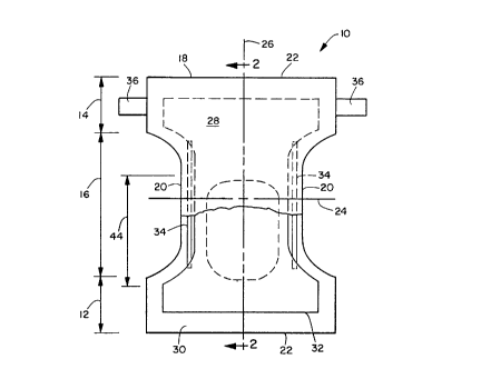
Figure 1 is a representative plan view of the diaper 10 of the
present invention in its flat-out, uncontracted state (i.e., with all
elastic induced gathering and contraction removed) with portions of
the structure being partially cut away to more clearly show the
construction of the diaper 10, and with the portion of the diaper 10
which contacts the wearer facing the viewer. The diaper 10 is shown
in Figure 1 to have a front waistband region 12, a back waistband
region 14, a crotch region 16, and a periphery 18 which is defined by
the outer edges of the diaper in which the longitudinal edges are
designated 20 and the end edges are designated 22. The diaper
additionally has a transverse center line 24 and a longitudinal
center line 26.
The diaper 10 comprises a liquid permeable top sheet 28; a
substantially liquid impermeable back sheet 30; an absorbent
structure generally shown at 32 positioned between the top sheet and
backsheet; and elastic members 34. Topsheet 28, backsheet 30,
_g_
CA 02286475 1999-10-26
absorbent structure 32, and the elastic members 34 may be assembled
in a variety of well-known diaper configurations. It should be
recognized, however, that in articles other than diapers, individual
components, such as top sheet 28, back sheet 30 and elastic
members 34, may be optional. The desirability of including
particular components in other absorbent articles would depend upon
their intended end use.
In the shown embodiment of diaper 10, top sheet 28 and the backsheet
30 are coextensive and have length and width dimensions generally
larger than those of the absorbent structure 32. The top sheet 28 is
associated with and superimposed on the back sheet 30, thereby
defining the periphery 18 of the diaper 10. The periphery delimits
the outer perimeter or the edges of the diaper 10, and comprises end
edges 22 and longitudinal edges 20. The diaper 10 has front and back
waistband regions 12 and 14, respectively extending from the end
edges 22 of the diaper periphery 18 toward the transverse center line -
24 of the diaper a distance from about 2 percent to about 10 percent
and preferably about 5 percent of the length of the diaper 10. The
waistband regions comprise those upper portions of the diaper 10,
which when worn, wholly or partially cover or encircle the waist or
mid-lower torso of the wearer. The intermediate, crotch region 16
lies between and interconnects waistband regions 12 and 14, and
comprises that portion of the diaper 10 which, when worn, is
positioned between the legs of the wearer and covers the lower torso
of the wearer. Thus, the crotch region 16 is the area where repeated
fluid surge typically occur in the diaper 10 or other disposable
absorbent article.
The top sheet 28, if employed, presents a body-facing surface which
is compliant, soft-feeling, and non-irritating to the wearer's skin.
Further, the top sheet 28 is sufficiently porous to be liquid
permeable, permitting liquid to readily penetrate through its
thickness. A suitable top sheet 28 may be manufactured from a wide
range of web materials, such as porous foams, reticulated foams,
apertured plastic films, natural fibers (for example, wood or cotton
fibers), synthetic fibers (for example, polyester or polypropylene
-9-
CA 02286475 1999-10-26
fibers), or a combination of natural and synthetic fibers. The top
sheet 28 is typically employed to help isolate the wearer's skin from
liquids held in the absorbent structure 32.
Various woven and nonwoven fabrics can be used for the top sheet 28.
For example, the topsheet may be composed of a meltblown or
spunbonded web of polyolefin fibers. The topsheet may also be a
bonded-carded-web composed of natural and synthetic fibers. The term
"nonwoven web" means a web of material which is formed without the
aid of a textile weaving or knitting process. The term "tabrics° is
used to refer to all of the woven, knitted and nonwoven fibrous webs.
The back sheet 30 is substantially impermeable to liquids and is
typically manufactured from a thin plastic film, or other flexible
liquid-impermeable material. As used in the present specification,
the term "flexible" refers to materials which are compliant and which
will readily conform to the general shape and contours of the
wearer's body. The back sheet 30 prevents the exudates contained in
the absorbent structure 32 from wetting articles such as bedsheets
and overgarments which contact the diaper 10. In the shown
embodiment, the back sheet 30 is a polyethylene film having a
thickness of from about 0.012 millimeters (0.5 mil) to 0.051
millimeters (2.0 mils). Alternatively, the back sheet rnay be a woven
or nonwoven fibrous web layer which has been constructed or treated
to impart the desired level of liquid impermeability.
Back sheet 30 may optionally be composed of a "breathable" material
which permits vapors to escape from the absorbent structure 32 while
still preventing liquid exudates from passing through the back sheet.
The back sheet can also be embossed and/or matte finished to provide
a more aesthetically pleasing appearance.
The size of the back sheet 30 is determined by the size of the
absorbent structure 32 and the exact diaper design selected. The
back sheet 30, for example, may have a generally T-shape, a generally
I-shape or a modified hourglass shape, and may extend beyond the
- 10 -
CA 02286475 1999-10-26
terminal edges of absorbent structure 32 by a selected distance,
e.g., 1.3 centimeters to 2.5 centimeters (0.5 to 1.0 inch).
The top sheet 28 and the back sheet 30 are connected or otherwise
associated together in an operable manner. As used therein, the term
"associated" encompasses configuration of the top sheet 28 is
directly joined to the back sheet 30 by affixing the top sheet 28
directly to the back sheet 30, and configurations whereby the top
sheet 28 is then directly joined to the back sheet 30 by affixing the
top sheet 28 to intermediate members which in turn are affixed to the
back sheet 30. The top sheet 28 and the back sheet 30 can be affixed
directly to each other in the diaper periphery 18 by attachment means
(not shown) such as an adhesive, sonic bonds, thermal bonds or any
other attachment means known in the art. For example, a uniform
continuous layer of adhesive, a patterned layer of adhesive, or an
array of separate lines or spots of construction adhesive may be used .
to affix the top sheet 28 to the back sheet 30. -
Fastening means, such as tape tab fasteners 36, are typically applied
to the back waistband region 14 of the diaper 10 to provide a
mechanism for holding the diaper on the wearer. The tape tab
fasteners 36 can be any of those well known in the art, and are
typically applied to the corners of the diaper 10. For. example,
mechanical fasteners, hook and loop fasteners, snaps, pins or
buckles, may be used rather than, or in combination with adhesives
and other jeans. It should be understood that is may be possible to
dispense with the fasteners in a given design configuration.
The elastic members 34, if included in the particular article, are
disposed adjacent the periphery 18 of the diaper 10, preferably along
each longitudinal edge 20 so that the elastic members 34 tend to draw
and hold the diaper 10 against the legs of the wearer. Elastic
members 34 may also be disposed adjacent either or both of the end
edges 22 of the diaper 10 to provide an elasticized waistband. It
should be noted that elasticized leg gathers and waist gathers are
typically used in conventional diapers to reduce leakage caused by
inadequacies of conventional absorbent structures and materials. In
- 11 -
CA 02286475 1999-10-26
some instances the present invention may be advantageously configured
to lessen reliance on the elasticized gathers for liquid containment
purposes.
The elastic members 34 are secured to the diaper 10 in an elastically
contractible condition so that in a normal under strain
configuration, the elastic members effectively contract against the
diaper 10. The elastic members 34 can be secured in an elastically
contractible condition in at least two ways, for example, the elastic
members 34 may be stretched and secured while the diaper 10 is in an
uncontracted condition. Alternatively, the diaper 10 may be
contracted, for example, by pleating, and the elastic members 34
secured and connected to the diaper 10 while the elastic members 34
are in their unrelaxed or unstretched condition. Still other means,
such as heat-shrink elastic material, may be used to gather the
garment.
In the embodiment illustrated in Figure 1, the elastic members 34
extend essentially the length of the crotch region 16 of the diaper
10. Alternatively, the, elastic members 34 may extend the entire
length of the diaper 10, or any other length suitable providing the
arrangement of elastically contractible lines desired for the
particular diaper design.
The elastic members 34 may have any of a multitude of configurations.
For example, the width of the individual elastic members 34 may be
varied from 0.25 millimeters (0.01 inches) to 25 millimeters
(~1.0 inches) or more; the elastic members 34 may comprise a single
strand of elastic material or may comprise several parallel or non-
parallel strands of elastic material; or may be applied in a
rectilinear or curvilinear arrangement. The elastic members 34 may
be affixed to the diaper in any of several ways which are known in
the art. For example, the elastic members 34 may be ultrasonically
bonded, heat and pressure sealed using a variety of bonding patterns
or adhesively bonded to the diaper 10.
- 12 -
CA 02286475 1999-10-26
The absorbent structure 32 is positioned between the top sheet 28 and
the back sheet 30 to form the diaper 10. The absorbent structure is
generally compressible, conformable, non-irritating to the wearer's
skin, and capable of absorbing and retaining liquid body exudates.
Referring to Figures 2-6, it should be understood that, for purposes
of this invention, the absorbent structure could comprise a single,
integral piece of material, or alternatively could comprise a
plurality of individual separate pieces of material. Where the
absorbent structure comprises a single, integral piece of material,
the material could include selected structural features formed in
different regions thereof. Where the absorbent structure comprises
multiple pieces, the pieces may be configured as layers or other
nonplanar shapes. Furthermore, the individual pieces may be
coextensive or non-coextensive, depending upon the requirements of
the product. It is preferred, however, that each of the individual
pieces be arranged in an operable, intimate contact along at least a
portion of its boundary with at least one other adjacent piece of the
absorbent structure. Preferably, each piece is connected to an
adjacent portion of the absorbent structure by a suitable bonding
and/or fiber entanglement mechanism, such as ultrasonic or adhesive
bonding, or mechanical or hydraulic needling.
In the embodiment representatively shown in Figure 3, absorbent
structure 32 includes a back section 38 and a front section 40, and
the front section has an end region 42 and a target zone 44. The
absorbent article generally comprises a liquid surge management
portion 46 (shown by the dotted lines), and a liquid retention
portion 48 arranged in liquid communication with surge management
portion 46. The absorbent structure additionally has a transverse
center line 56 and a longitudinal center line 58. At least a part of
surge management portion 46 is located within target zone 44, and
preferably, the surge management portion has an areal extent which
extends completely over target zone 44. Retention portion 48 is
positioned in liquid communication with surge management portion 46
to receive liquids released from the surge management portion, and to
hold and store the liquid. The absorbent structure may be configured
with a part of retention portion 48 located within target zone 44 and
- 13 -
CA 02286475 1999-10-26
the remainder of retention portion 4$ located outside of the target
zone. In an alternative arrangement, none of the retention portion
is positioned within target zone 44, and the retention portion is
totally located outside of the target zone. In yet another
arrangement, all of retention portion 48 may be positioned within
target zone 44. The retention portion can include a recess area
which wholly or partially surrounds surge management portion 46
(Figure 6), or can be entirely positioned below the surge management
portion (Figure 5). The arrangement which includes the recess in
retention portion 48 can advantageously increase the area of contact
and liquid communication between the retention portion and surge
management portion 48.
Front section 40 is conceptually divided into three regions
comprising two transversely spaced ear regions 50 and 52
respectively, and a central region 54. Front section 40 is
contiguous with back section 38, and the back and front sections of .
absorbent structure 32 extend away from the end edges 60 of the
absorbent structure 32 toward the transverse center line 56. The
relative dimensions of the various sections and portions of the
diaper 10, and of the absorbent structure 32, can be varied depending
on materials used and the desired product needs. For example, the
front portion 40 can extend over a distance corresponding to about
one-half to two-thirds, or even three-fourths of the length of
absorbent structure 32. The front section 40 is constructed to
encompass all the fluid target zone 44 of the absorbent structure 32
within the diaper or other absorbent article.
The front portion 40 has an end region 42 and a target zone 44. The
end region 42 comprises the portion of the front section 40 extending
a selected distance from the respective end edge 60 of the absorbent
structure 32 toward the transverse center line 56. The target
zone 44 is contiguous with end region 42 and back section 38, and
encompasses the area where repeated liquid surges typically occur in
absorbent structure 32. The particular location where liquid is
discharged, such as during micturition, varies depending on the age
and gender of the wearer. For example, male infants tend to urinate
- 14 -
CA 02286475 1999-10-26
further toward the front end of the diaper. The female target zone
is located closer to the center of the crotch. As a result, the
shape and relative longitudinal placement of the surge management
portion 46 can be selected to best correspond with the actual target
zone of either or both categories of wearers.
The ear regions 50 and 52 comprise portions which generally extend
from the longitudinal edges 20 (Figure 1) of the periphery 18 toward
the longitudinal center line a distance from one-tenth to one-third
of the overall width of the absorbent structure 32, and connect to
central region 54. Thus, the ear regions are configured to engage
the sides of the wearer's waist and torso, and the central region 54
is configured to engage the medial portion of the wearer's waist and
torso.
The absorbent structure 32 may be manufactured in a wide variety of
sizes and shapes (for example, rectangular, trapezoidal, T-shape,
I-shape, hourglass shape, etc.) and from a wide variety of materials.
The size and the absorbent capacity of the absorbent structure 32
should be compatible with the size of the intended wearer and the
liquid loading imparted by the intended use of the absorbent article.
Further, the size and the absorbent capacity of the absorbent
structure 32 can be varied to accommodate wearers ranging from
infants through adults. In addition, it has been found that with the
present invention, the densities and/or basis weights of the
respective surge management 46 and retention 48 portions, as well as
their relative ratios, can be varied. -
Various types of wettable, hydrophilic fibrous material can be used
in the component parts of absorbent structure 32. Examples of
suitable fibers include naturally occurring organic fibers composed
of intrinsically wettable material, such as cellulosic fibers;
synthetic fibers composed of cellulose or cellulose derivatives, such
as rayon fibers; inorganic fibers composed of an inherently wettable
material, such as glass fibers; synthetic fibers made from inherently
wettable thermoplastic polymers, such as particular polyester or
polyamide fibers; and synthetic fibers composed of a nonwettable
- 15 -
CA 02286475 1999-10-26
thermoplastic polymer, such as polypropylene fibers, which have been
hydrophilized by appropriate means. The fibers may be hydrophilized,
for example, by treatment with silica, treatment with a material
which has a suitable hydrophilic moiety and is not readily removable
from the fiber, or by sheathing the nonwettable, hydrophobic fiber
with a hydrophilic polymer during or after the formation of the
fiber. For the purposes of the present invention, it is contemplated
that selected blends of the various types of fibers mentioned above
may also be employed.
As used herein, the term "hydrophilic" describes fibers or the
surfaces of fibers which are wetted by the aqueous liquids in contact
with the fibers. The degree of wetting of the materials can, in
turn, be described in terms of the contact angles and the surface
tensions of the liquids and materials involved. Equipment and
techniques suitable for measuring the wettability of particular .
fibers or blends of fibers used for the surge management portion 46
can be provided by a Cahn SFA-222 Surface Force Analyzer System.
When measured with this system in accordance with the procedure
described in detail herein below, fibers having contact angles less
than 90° are designated "wettable", while fibers having contact
angles greater than 90° are designated "nonwettable".
A capillary force differential created at the interface between the
surge management 46 and retention 48 portions can improve the
containment characteristics of the absorbent structure 32. If surge
management portion 46 has and maintains a relatively lower capillary
attraction, as compared to the capillary attraction exhibited by
retention portion 48, liquid surges occurring in the target zone 44
tend to be desorbed more readily from the surge management portion
and into the retention portion. Because the retention portion 48 can
thereby have a relatively higher capillarity than the surge
management portion 46, the liquid surges tend to be drawn into the
retention portion 48 and distributed to the more remote regions
thereof by wicking along the plane generally defined by the retention
portion.
- 16 -
CA 022864'75 1999-10-26
As representatively shown in Figures 4, retention portion 48 can be
situated underlying the surge management portion 46 in target
zone 44, and can substantially define the boundaries of absorbent
structure 32. Preferably, the retention portion 48 comprises
hydrophilic fibers, such as cellulosic fluff, mixed with absorbent
gelling particles which have a high retention capacity even under
compressive loads applied in use. In other alternative arrangements,
retention portion 48 may comprise a mixture of superabsorbent
hydrogel particles and synthetic polymer meltblown fibers, or a
mixture of superabsorbent particles with a fibrous coform material
comprising a blend of natural fibers and/or synthetic polymer fibers.
Suitable absorbent gelling materials can be inorganic materials such
as silica gels or organic compounds such as cross-linked polymers.
Cross-linking may be by covalent, ionic, Van der Waals, or hydrogen
bonding. Examples of absorbent gelling material polymers include _
polyacrylamides, polyvinyl alcohol, ethylene malefic anhydride -
copolymers, polyvinyl ethers, hydroxypropyl cellulose, carboxymal
methyl cellulose, polyvinylmorpholinone, polymers and copolymers of
vinyl sulfonic acid, polyacrylates, polyacrylamides, polyvinyl
pyrrolidone and the like. Further polymers suitable for use in the
absorbent structure include hydrolyzed, acrylonitrile grafted starch,
acrylic acid grafted starch, polyacrylates and isobutylene malefic
anhydride copolymers or mixtures thereof. Other suitable hydrogels
are disclosed by Assarson et al. in U.S. Patent No. 3,902,236 issued
August 26, 1975. Processes for preparing hydxogels are disclosed in
U.S. Patent No. 4,076,663 issued February 28, 1978 to Masuda et al.
and U.S. Patent No. 4,286,082 issued August 25, 1981 to Tsubakimoto
et al .
As mentioned previously, the absorbent gelling material used in
retention portion 48 is generally in the form of discrete particles.
The particles can be of any desired shape, for example, spiral or
semi-spiral, cubic, rod-like, polyhedral, etc. Shapes having a large
greatest dimension/smallest dimension ratio, like needles, flakes,
and fibers, are also contemplated for use herein. Conglomerates of
- 17 -
CA 02286475 1999-10-26
particles of absorbent gelling material may also be used in retention
portion 48.
Preferred for use are particles having an average size of from about
50 microns to about 1 millimeter. "Particle size" as used herein
means the weighted average of the smallest dimension of the
individual particles.
Where retention portion 48 comprises a mixture of absorbent gelling
particles and cellulosic fluff, the retention portion may, for
example, be densified to a density within the range of about 0.08-0.3
grams per cubic centimeter, and may contain about 5-70 percent by
weight of the absorbent gelling material. In addition, the basis
weight of the resultant web can range from about 200 to 3000 gsm.
With reference to diaper articles, the density of the retention
portion 48 is calculated from its basis weight and thickness, and is _
measured on newly unpacked, unfolded and desiccated diapers. For -
measuring bulk thickness to calculate densities, a suitable device is
a TMI foam thickness gauge, Model No. TM1-49-21 or its equivalent.
The apparatus is supplied by Testing Machines, Inc. of Amityville,
New York.
Attempts to ameliorate gel blocking in typical fluid retention
structures comprising mixtures of hydrophilic fiber and gelling
material have employed a densification of such absorbent structures
to ostensibly enhance the liquid wicking rate along the general plane
of the structure (X-Y direction) as a result of a higher capillary
force created by the smaller pore sizes within the matrix of
densified fibers. Although densifying the absorbent structure does
reduce the bulk thickness of the structure, the higher density may
excessively reduce the rate of liquid intake.
In particular, the densification of the retention portion 48 can
reduce the rate of liquid movement into the retention portion 48
along the thickness dimension, which is the direction normal to the
general X-Y plane of the article (i.e., the Z-direction). It is
believed that as higher concentrations of absorbent gelling material
- 18 -
CA 02286475 1999-10-26
are located in the area of desorption underneath the surge management
portion 46, a greater gel blocking effect may be created thereby
reducing the liquid intake rate. Preferably, the materials in target
zone 44 incorporate reduced amounts of absorbent gelling material,
thereby reducing the incidence of gel-blocking in this zone and
improving the liquid intake rate.
The surge management portion 46 can be of any desired shape
consistent with the absorbency requirements of the absorbent
structure 32. Suitable shapes include for example, circular,
rectangular, triangular, trapezoidal, oblong, dog-boned, hourglass-
shaped, or oval. Preferred shapes of the surge management portion
are those that increase the contacting, liquid communicating surface
area between the surge management portion 46 and the retention
portion 48 so that the relative capillarity difference between the
portions can be fully utilized. In preferred embodiments, such as _
shown in Figures 3-6 and 8-9, the surge management portion can be -
oval-shaped with a top surface area of about 45 square inches (about
290 cm2).
The surge management portion 46 should have an operable level of
density and basis weight to quickly collect and temporarily hold
liquid surges, and to transport the liquid from the initial entrance
point to other parts of the absorbent structure 32, particularly the
retention portion 48. This configuration helps prevent the liquid
from pooling and collecting on the top sheet 28, thereby reducing the
feeling of wetness by the wearer.
Surge management portion 46 preferably has a generally uniform
thickness and cross-sectional area. Alternatively, a configuration
can be used wherein the bodyside surface area of the surge management
portion is greater or less than the surface area of a section taken
along an X-Y plane located below the bodyside surface of the surge
management portion.
With reference to Figure 2, surge management portion 46, can be a
separately formed absorbent layer, which lies on top of the retention
- 19 -
CA 02286475 1999-10-26
portion 48. Thus, the surge management portion 46 need not comprise
the entire thickness of the absorbent structure 32. It should be
understood, however, that the surge management portion 46 could
optionally extend the entire thickness of the absorbent structure 32
so that the capillary flow of liquid into retention portion 48 occurs
primarily in the generally sideways (X-Y) direction.
Although the surge management portion 46 may be positioned anywhere
along the absorbent structure 32, it has been found that the surge
management portion 46 may function more efficiently when it is offset
toward the front waistband of the garment and transversely centered
within the front section 40 of the absorbent structure 32. Thus, the
surge management portion 46 is approximately centered about the
longitudinal center line 58 of the absorbent structure 32, and
positioned primarily in the central region 54 of the front section 40
of the absorbent structure 32. In the illustrated embodiment, none of
the surge management portion 46 is located in the ear regions of -
50 and 52.
The generally forward, offset positioning of the surge management
portion 46 can be defined by specifying the percentage of the top
surface area of the surge management portion 46 which is found
forward of a particular. reference point, such as transverse
centerline 24, along the length of the absorbent structure 32. The
positioning of the surge management portion 46 can alternatively be
defined with respect to the volume of the surge management portion
positioned forward of a reference point.
As shown in Figures 2 and 4-6, the surge management portion 46 may
comprise a separate layer which is positioned over another, separate
layer comprising the retention portion, thereby forming a dual-layer
core arrangement. The surge management portion serves to quickly
collect and temporarily hold discharged liquids, to transport such
liquids from the point of initial contact and spread the liquid to
other parts of the surge management portion, and then to eventually
release such liquids into the layer or layers comprising the
retention portion 48. In the shown embodiment, the layer comprising
- 20 -
CA 02286475 1999-10-26
the surge management portion is substantially free of absorbent
gelling material.
Surge management portion 46 may, however, contain a very small amount
of particulate gelling material to help acquire an initial liquid
surge, but the amount should not be excessive. As illustrated in
Figures 12 and 13, when excessive amounts of particulate absorbent
gelling material are maintained in the target zone 44, the particles
can cause the structure to retain and hold unacceptably high amounts
of the liquid. Further, the transport of liquids away from the
target zone 44 to other sections of the absorbent structure 32,
particularly the retention portion 48, can be undesirably impaired.
The dual-layer arrangement can be of any desired shape consistent
with comfortable fit. Suitable shapes include, for example, circular,
rectangular, trapezoidal, oblong, hourglass-shaped or oval. With
reference to Figure 5, the entire absorbent structure 32, or any -
individual~ portions thereof, such as the retention portion, can be
wrapped in a hydrophilic high wet-strength envelope web, such as a
high wet strength tissue or a synthetic fibrous web, to minimize the
potential for particles of absorbent gelling material to migrate out
of the absorbent structure 32, particularly out of the retention
portion 48. Such overwrapping web can also increase the in-use
integrity of the dual layer absorbent structure. The web can, in
fact, be glued to the absorbent structure 32 and to other components
of the product construction. -
With reference to Figures 8 and 9, the absorbent structure of the
present invention may advantageously comprise an integrally formed
arrangement composed of non-uniform, differentially-configured
fibrous sections wherein particular component sections, such as surge
management portion 46 and retention portion 48, include fibers which
are interwoven or otherwise entangled together at the fibrous
interfaces between the components. Such an arrangement can
advantageously improve the effectiveness of the liquid transport from
the surge management portion and into the retention portion.
- 21 -
CA 02286475 1999-10-26
It is contemplated that a surge management portion constructed in
accordance with the present invention will be tailored and adjusted
to accommodate various levels of performance demand imparted during
actual use. For example, mild urinary incontinence and menstrual
flow pads involve different delivery rates, volumes and timing than
infant urine insults. Moreover, the liquid in the surge can vary in
terms of the liquid viscosity, surface tension, temperature, and
other physical properties which could affect the performance of the
fabric in the various actual product end usages.
With respect to absorbent articles, wherein reduced bulk or minimum
cost may be important, the surge management and retention portions
need not take on the entire overall shape of the garment. Rather,
they could be generally configured and located to cover only the
genital region of the wearer. For instance, both the surge
management portion and the retention portion could be offset toward .
the front section of the garment outer cover 30. -
It has been found that an effective fabric for constructing the surge
management portion can be distinctively characterized by some or all
of the following qualities: (a) a resilient structure having a
selected basis weight; (b) an appropriate amount of total fiber-
surface-area within the internal structure of the fabric; (c) a
balance of fiber-surface-areas which are wettable and non-wettable;
and (d) an appropriate distribution of the fibers within the
. volumetric-space defined by the surge management portion. More
particularly, the surge management portion can incorporate
distinctive parameters which help characterize the liquid capillarity
and other features of surge management portion 46. The parameters
include the total amount of fiber-surface-area per standard unit of
fabric; the amount of wettable-surface-area of such fibers per
standard unit of fabric; a total-wettable-surface-area multiplied-by-
density parameter; and a total-nonwettable-surface-area-multiplied-
by-density parameter.
- 22 -
CA 02286475 1999-10-26
Resiliencv and Basis Weight
A resilient fabric structure allows the fluid surge management
portion of the present invention to:
1. stay open under load, to maintain void volume in the
fabric;
2. resist collapsing when wetted to better release liquid and
to better allow the fabric to be desorbed; and
3. be regenerating after being wetted to preserve void volume
capacity for successive insult(s).
A particular embodiment of the present invention which provides
desired levels of resiliency is a fabric comprising a selected
proportion of relatively larger, stiffer fibers, such as the bonded-
carded-web of Example I.
The basis weight of surge management portion 46 is at least about .
60 grams per square meter, and preferably is at least about 90 gsm to
help provide the total void volume capacity desired for effective
operation. In a particular aspect of the invention the basis weight
is within the range of about 60-3000 gsm and preferably is within the
range of about 90-3000 gsm to provide further advantages. In a
further aspect of the invention, the surge management portion has a
basis weight which is at least about 100 gsm, and preferably is
within the range of about 100-3000 gsm to provide improved
effectiveness.
The amount of basis weight is important for providing a total holding
capacity which is adequate to temporarily retain the amount of liquid
that is typically discharged by a wearer during a single surge/insult
of liquid into the absorbent article. For instance, the material of
Example 9 had inadequate basis weight, and had insufficient overall,
total holding capacity to provide the desired temporary reservoir for
suitably containing a typical amount of liquid surge. Such a
configuration can result in excessive pooling of liquid against the
wearer's skin or excessive run-off of liquid.
- 23 -
CA 02286475 1999-10-26
It will be readily apparent that absorbent articles requiring more
surge capacity may also require proportionally greater amounts of
surge management material. The surge management material, however,
need not be of uniform basis weight throughout its areal extent, but
instead can be arranged so that some sections have more surge
management material compared to other sections. For the purposes of
the present invention, the effective basis weight will be the weight
of the surge management material divided by the area over which the
surge management portion extends.
Surface Area
Liquid ordinarily flows along fiber surfaces, and the fiber surfaces
are the usual transport routes to the void volume defined by the
interfiber spacings of the fabric structure. By properly selecting
the amounts and spatial arrangements of the wettable and nonwettable
fiber surface areas per standard unit of fabric, the fluid access to .
the void volume of the material can be improved without adversely
affecting the fluid release characteristics. Referring to the
photomicrographs shown in Figure 7A and 7B, a preferred fabric for
the surge management portion can comprise a generally homogeneous
blend of fine small diameter fibers intermingled with stiffer, larger
diameter fibers. The finer the fiber size, the greater the available
surface area per unit weight. Therefore, increased surface area is
generally provided by using more fibers and finer fibers. High
amounts of wettable surface area per unit weight of fabric can also
be provided by fibrous webs composed of relatively large fibers with
a high wettable surface area per unit weight, e.g. wood pulp fluff
fibers. Although larger, stiffer fibers can enhance the ability of
the material to maintain the desired structure when wetted and
subjected to compressive forces, such as the compressive forces
typically applied by the wearer of the garment during use, they may
adversely affect tactile properties of the fabric and may not
adequately increase the fiber surface area. ,
In a particular aspect of the invention, surge management portion 46
has a total fiber-surface-area value within the range of about
- 24 -
CA 02286475 1999-10-26
5-90 square meters per 100 grams of surge management material. In a
further aspect of the invention, the surge management portion
has a total fiber-surface-area value within the range of about
5-54 m2 per 100 grams of surge management material, and in yet
another aspect of the invention, the surge management portion has a
total fiber-surface-area value within the range of about 12-54 m2 per
100 grams of surge management material to provide further advantages.
The "fiber-surface-area" distributed within a particular quantity of
surge management material can be determined by employing an image
analysis technique which will be described in detail herein below.
The fiber-surface-area values of surge management materials composed
of fibers with modified, nonuniform cross-sections can be determined
by employing the well known BET method which is described by
Brunauer, Emmett and Teller, Journal of the American Chemical
Societ , 60,309 (1938), and which is hereby incorporated by reference .
into the present description. -
The surge management portion can be a mixture of wettable and
nonwettable fibers or can be composed entirely of wettable fibers.
An appropriate fabric for the surge management portion should have a
selected amount of wettable fiber surface area (SAw) to (a) initially
attract liquid into the fabric structure, (b) help provide rapid
fluid uptake, and (c) help fill the void volume capacity of that
fabric structure.
Each incidence of liquid surge should "linger" in the fabric
structure of the surge management portion long enough to occupy at
least a part of its void volume capacity, instead of simply passing
through in a relatively straight-line path. As illustrated in
Figure 10, a conventional layer of material can allow a substantially
uninterrupted passage of liquid in a generally straight-line path
without lingering in the structure prior to its release from the
structure (large arrows).
The surge management portion of the invention can advantageously
provide for a rapid uptake of the liquid surges (Figure 11A)
- 25 -
CA 02286475 1999-10-26
delivered onto the target zone and also allow a spreading of the
liquid through the void volume of its structure (Figure 11B) to
temporarily fill it. The surge management portion can then be
desorbed after a certain, limited period of time (Figure 11C) through
the operation of an underlying or surrounding liquid retention
portion {not shown). Thus, the liquid surge can "linger" in the
fabric structure to occupy the void volume for a discrete,
transitional period instead of simply passing directly through in a
generally straight-line path.
Wettable Surface Area (SAw)
In a particular aspect of the invention, the surge management portion
comprises a fibrous material having a wettable fiber-surface-area
{SAw) which is greater than zero and not more than about 70 square
meters/100 grams of the surge management material. Preferably the
surge management material has a wettable fiber-surface-area value
which is greater than zero and not more than about 54 square meters
per 100 grams of fabric. To provide further advantages, the wettable
fiber-surface-area value is not less than about 3 and not more than
about 54 square meters per 100 grams of fabric.
The total wettable surface area must be greater than zero so that
some degree of wettability is present to initiate fluid penetration
into the fabric structure and utilize its void volume capacity. With
reference to Table 2 set forth herein below, Example 10 has no
wettable surface area and exhibits excessively high penetration time
values and low void capacity values. For fibrous structures having a
wettable surface area of greater than 70 square meters per 100 grams
o'F fabric there can be too much wettable surface attracting fluid,
thus not allowing the structure to desorb or release liquid to other
sections of an article. For instance, see Example 13.
The requirement for wettable fiber surface area can be met by using
naturally wettable fiber components with measured contact angles of
less than 90° in the fabric structure of the surge management
portion. Such fiber materials include cotton, rayon and wood pulp.
- 26 -
CA 02286475 1999-10-26
Other suitable fiber materials can be inherently wettable synthetic
polymers; hydrophilized or surface treated polymers, etc.; or
materials having permanent, i.e, non-migratory, surface treatments
applied to nonwettable substrate materials, for example,
polypropylene, to reduce the contact angle below 90'.
Wettable Surface Area Times Density [(SAw)*D]
In another aspect of the invention, surge management portion 46 can
be characterized by a wettable fiber-surface-area-times-density
[(SAw)*D] which is greater than zero and not more than about
7m2/100cm3. Preferably the wettable fiber-surface-area-times-density
value is not more than about 5m2/100cm3, and more preferably, is not
more than about 4.Om2/100cm3 to provide improved effectiveness.
This structural parameter indicates how closely together the wettable .
surfaces of the structure are located. The value of this parameter -
should be greater than zero to insure that some wettable surface area
is present to initiate rapid liquid penetration. A lower value for
this parameter indicates that the wettable surface areas are somewhat
spread out in the fabric structure. In contrast, a higher value
would indicate that the wettable surface areas are fairly close
together. When this value is too high, the wettable surface areas
are so close together that the structure has strong affinity for
liquids, and the liquids are not readily desorbed. As a result, the
surge management portion may not adequately release the liquid surge
to the desorbing retention portion. For example, the wettable
surface area times density value [SAw*D] for Example 11 is
excessively high. As a result, the fabric is unable to sufficiently
release the fluid surge, and exhibits excessively high residual
values.
Non-wettable Surface Area (SAnw) Times Density, [(SAnw)*D]
40
In a further aspect of the invention, surge management portion 46 has
a nonwettable fiber-surface-area (SAnw)-times-density value,
[(SAnw)*D], which is not more than about 1.1 m2/100 cm3. Preferably,
- 27 -
CA 02286475 1999-10-26
the nonwettable fiber-surface-area-times-density value is not more
than about 0.71 m2/100 cm3 to provide improved performance.
This parameter indicates how closely together the nonwettable,
fibrous components are placed in the fabric structure. The parameter
value can be zero, such as when the fabric is composed of 100 percent
wettable fibers. A low value indicates the nonwettable surface areas
are somewhat spread-out, and a higher value indicates the nonwettable
surface areas are fairly close together. When this value is above
about 1.1, m2/100 cm3, the nonwettable components may be too close
together, hindering liquid penetration. This can excessively
increase the amount of time required for the liquid to penetrate into
the fabric structure, and the fabric may not have a sufficiently
rapid uptake of the liquid. Likewise, a higher value for this
parameter can indicate that the pores between the nonwettable fiber
surfaces are tightly closed. As a result, the fabric structure may .
not be able to readily release fluid into a desorbing, retaining -
portion. For instance, Example 12 has a high nonwettable fiber-
surface-area-times-density value, and does not sufficiently release
liquid to a desorbing material. In addition, the material of Example
12 exhibits excessively high values for uptake time, particularly on
repeat insults.
Total Surface Area (SAt)
In a further aspect of the invention, surge management portion 46 has
a total fiber-surface-area (SAt) which is not less than about 5 not
more than about 90 square meters per 100 grams of surge management
material. Preferably, the surge management portion has a total
fiber-surface-area value of not less than about 5 and not more than
about 54 square meters per 100 grams of surge management material to
provide improved performance. To provide further advantages, the
surge management portion has a total fiber-surface-area value of not
less than about 12 and not more than about 54 m2 per 100 gm of the
surge management material.
- 28 -
CA 02286475 1999-10-26
Higher total surface area values indicate that the fabric structure
can retain too much fluid, i.e., the fabrics exhibit excessively high
residual values due to poor desorption performance. The structures
do not adequately release the liquid surges into the retention,
storage section of the absorbent structure. For instance, Example 13
illustrates this poor desorption. High total fiber-surface-area
values can occur when wettable and/or nonwettable components are
present in the maximum of each allowable range. Thus, the total
surface area (SAt) parameter can indicate whether a total blend of
wettable and nonwettable fibers is balanced properly within the
structure.
FABRIC DENSITY DETERMINATIONS
Density measurements can be taken using a TMI foam thickness gauge
Model No. TMI-49-21, supplied by Testing Machines, Inc. of
Amityville, New York. This type of gauge allows bulk thickness
measurements to be made while exerting a very low compressive force
of about 0.05 psi (about 0.34 kPa) on the fabric.
PENETRATION RATE DESORPTION (PRD) TEST
This test allows the testing and screening of fabrics to determine
whether the structures thereof provide required values for particular
surge management parameters. Further, it allows the testing of
individual fabrics whereby the performance of the fabrics themselves _
can be measured without variables being introduced by other
components, such as lofty liner fabrics which are often placed on the
body side surface of absorbent structures to aid in dryness, etc.
The PRD test is conducted using liquid flow conditions (e. g., amount,
flow rate and velocity) which closely simulate conditions experienced
by a surge management portion during use. The fluid used in the PRD
test is a synthetic urine, such as described in U.S. Patent
No. 4,699,619, delivered at a temperature of about 37°C (about
98.6°F).
_ 29 _
a
CA 02286475 1999-10-26
With reference to Figure 14, a testing apparatus generally shown at
110, includes a test holder base 116 and a hollow tube, generally
indicated at 112. The tube is composed of, for example, Lucite~ or
other clear strong material, which allows a view of the liquid
penetration during testing. The tube 112 has a 3 inch inner diameter
and a wall thickness of about 0.25 inches. The tube stands
vertically on end and is approximately 6 inches tall. The vertical
tube wall 114 is sealed to a flat base 116 which is composed of a
similar clear material, for example Lucite~, and which measures about
6 inches by 6 inches square. Three (3) holes 118, approximately 0.50
inches in diameter, are drilled through the wall 114 of tube 112 to
allow air circulation to the inside of the tube 112 and to avoid back
pressure buildup inside the tube. These holes 118 are equally spaced
around the circumference of the tube at relative positions of 0',
120' and 240°, and are placed 3 inches down from the upper edge 120
of the tube 112. Three small rectangular pieces composed of a clear
material, for example Lucite~, and having dimensions of 0.375 inches -
wide by 0.75 inches long by 0.25 inches thick are mounted to the
inside wall surface of tube 112 in a vertical position, forming
projections 122 extending into the inner diameter space of the tube
112. The three projections are placed 1.5 inches down from'the upper
edge 120 of the tube at 60', 180° and 300° intervals around the
circumference of the tube 114. The projections 122 are staggered
from the position of the air holes 118 as illustrated in Figure 14.
A three inch diameter round piece of a woven or an extruded plastic
mesh screen 124 (2 mesh per inch) is placed.horizontally inside the
upper portion of the tube to rest on the projections 122, as shown in
Figure 15. If desired, an annular support ring (not shown) may be
employed to help support the peripheral edges of the mesh screen.
The support ring would rest upon projections 122 and the edges of the
mesh screen would, in turn, rest upon the support ring. The support
ring is constructed and arranged so as to not impede the movement of
liquid through the test sample. The projections 122, the plastic
screen 124 and the supporting ring act as a sample support system.
Referring to Figure 16, synthetic urine for the test is supplied at a
rate of 15 milliliters per second through a miniature 12-volt DC
- 30 -
A
CA 02286475 1999-10-26
miniature gear pump (not shown) manufactured by Cole Parmer
Instrument Company of Chicago, Illinois. The liquid which is to be
delivered to the fabric sample, passes through a nozzle assembly 130
comprising a No. 316 stainless steel tube 129 fitted with a nozzle
tip 131 having an inner diameter of 0.103 inches. The temperature of
the synthetic urine is suitably controlled to provide a temperature
of about 37°C (about 98.6°F) at the time of delivery to the
fabric
sample. The nozzle and pump are configured to impart an initial
velocity of 210 centimeters per second to the fluid. The nozzle tip
is directed downwardly, along a direction perpendicular to the fabric
surface being tested, and is located approximately one inch from the
upper surface of the test fabric.
Procedure:
A preweighed, circular sample 126 of test fabric measuring 3 inches
in diameter is placed inside the tube 112 on the plastic screen 124.
A standard test amount of one hundred (100) milliliters of synthetic
urine is inputted to the fabric at a volume rate of 15 milliliters
per second through nozzle assembly 130. The time required for all
liquid to penetrate into the surface of the sample 126 is measured in
seconds, beginning from the initiation of the delivered liquid
insult, and is recorded. Typically, some liquid is held within the
sample 126, and some liquid passes through the sample and is
collected in the bottom 128 of tube 112. The sample 126, along with
the liquid held therein, is then removed from holder 112 and weighed.
The sample 126 is then placed on a 4 inch by 4 inch square desorption
pad composed of cellulosic wood pulp fluff mixed with superabsorbent
particles. To this purpose, the desorption pad can comprise a
mixture of softwood fluff designated "CR-54," available from
Kimberly-Clark Corporation, and a hardwood pulp fluff designated
Longlac 19~ also available from Kimberly-Clark Corporation which have
been air-laid according to conventional techniques to form a fibrous
web. About 12 percent of the dry weight of the desorption pad
comprises superabsorbent particles available from Hoechst-Celanese
Corporation as IM1500. The particles are mixed with the air laid
fluff fibers to form a pad having a density of about 0.1 gm/cc and a
- 31 -
CA 02286475 1999-10-26
basis weight of about 1400 gsm. The desorption pad should be
constructed and arranged such that after an immersed saturation with
synthetic urine under free-swell conditions for 5 min, the pad
retains at least 10 gm of synthetic urine per gram of desorption pad
after being subjected to an air pressure differential (vacuum
suction) of about 0.5 psi (about 3.45 kPa) applied across the
thickness of the pad for 5 min. A suitable weight (not shown) is
then placed on the fabric sample 126 to apply a pressure of 0.25 psi
over the entire sample to desorb the liquid from sample 126 and into
the desorption pad positioned immediately below the sample. After
minutes, the weight is removed and the sample 126 is weighed
again. This completes the first cycle. The desorption pad is
discarded, and a fresh desorption pad is obtained for the next cycle
of the procedure. The sample is then returned to supporting
15 screen 124 substantially without further drying or desorption of the
sample, and the testing cycle (introducing liquid, weighing,
desorbing and weighing) is repeated two more times for a total of -
three cycles. The three uptake-and-desorption cycles are completed
within a period of 60 min.
Measurements and Calculations
During the PRD Test procedure the following ten (10) items of data
are measured for each fabric sample tested. Sample weights are
designated in brackets:
1. The initial weight of the sample: [A].
- Z. Three (3) penetration times, i.e. one for each of the -
100 milliliter synthetic urine insults.
3. Three (3) saturated sample weights, that is, one weight
. after each insult: [Bn]; n = 1,2,3.
4. Three (3) final sample weights, that is, one weight after
each desorption cycle: [Cn]; n = 1,2,3.
Nine (9) values are to be determined by the PRD Test, that is, values
for each of three (3) parameters measured during each of the
three (3) successive synthetic urine insult cycles, are calculated as
follows:
- 32 -
CA 02286475 1999-10-26
1. Three uptake time values are measured and determined
directly from the penetration times (in seconds).
2. Temporary loading values measured as grams of fluid held
due to insult (n) per gram of fabric are calculated as:
(Temporary Loading)n = [Bn]-[A] ; n = 1,2,3
3. Release of fluid, residual values measured as grams of
fluid remaining after desorption (n) per gram of fabric,
are calculated as:
(Residual)n = [Cn]-[A] ; n = 1,2,3
The uptake time value is an indicator of the liquid uptake rate for a
fabric sample. The temporary loading value is a measure of the -
transitional reservoir capacity of a sample, and the residual value -
is a measure of the release characteristics of the fabric sample.
If the uptake time value is too high, the material of the surge
management portion can be adjusted by increasing the proportion of
the wettable-fiber-surface-area (SAw) of the fabric and/or by
decreasing the density of the bulk fabric. If the temporary loading
value is less than desired, the material of the surge management
portion can be adjusted by increasing the wettable-fiber-surface-area
- 30 (SAw) of the fabric and/or by increasing the density of the bulk
fabric. If the residual value is too high, the surge management
material can be adjusted by decreasing the wettable-fiber-surface-
a~rea (SAw) and/or by reducing the density of the bulk fabric. It
should be understood that the increase or decrease of the proportion
of wettable-fiber-surface-area will cause a corresponding but
opposite change in the relative proportion of the nonwettable-fiber-
surface-area (SAnw) within the fabric material.
The fabric can also be adjusted to address various combinations of
the uptake time, temporary loading and residual values. For example,
if the uptake time value and the temporary loading value are not
- 33 -
CA 02286475 1999-10-26
within desired ranges, the surge management material can be adjusted
by increasing the wettable-fiber-surface-area of the fabric. As a
further example, if the residual value and temporary loading value
are not within desired ranges, the surge management material can be
adjusted by decreasing the wettable-fiber-surface-area or by
decreasing the density of the bulk fabric.
FIBER WETTABILITY DETERMINATIONS
The wettability of fibers can be determined using contact angle
measurements on fibers. Repeat cycle, single fiber contact angle
measurements using distilled water were performed with a Cahn Surface
Force Analyzer (SFA222) and WET-TEKe data analysis software. The
SFA222 is available from Cahn Instruments, Inc., of Cerritos,
California, and the WET-TEK software is available from Biomaterials
International, Inc., of Salt Lake City, Utah. Fibers are tested
through three measurement cycles, and the distilled water bath is
changed between cycles one and two. Fibers are determined to be
"wettable" if all three of the repeat cycles measure a contact angle
of less than 90°. Otherwise, the fibers are deemed "nonwettable".
The test instrument is operated in accordance with the standard
operating techniques described in the Cahn SFA-222 System Instruction
Manual supplied by the manufacturer.
FIBER SURFACE AREA MEASUREMENTS
Surface areas of the fibers contained within a fabric can be
determined by a combination of mathematical and empirical methods,
depending upon the fibrous composition. Surface areas of fabrics
composed of round cross-section, staple fibers can be calculated
directly. Fabrics composed of round cross-section melt extruded
fibers (e. g. meltblown and spunbond fibers), can be examined with
known image analysis techniques to achieve a fiber diameter
distribution plot, or histogram. From the histogram, calculations
can be completed to determine the surface area values of the fibers.
The fiber-surface-areas within webs composed of modified cross-
section fibers, such as modified cross-section staple fibers,
modified cross-section melt extruded fibers and/or non-uniform cross-
- 34 -
CA 02286475 1999-10-26
section cellulosic fibers can be measured by the BET method of
Brunauer, Emmett and Teller, Journal of the American Chemical
Societ , 60, 309 (1938).
The fiber size histograms can be obtained by employing conventional
image analysis techniques, which are well known in the art. In a
suitable technique, six random 3/4 in x 1 in samples are taken of a
selected fabric and prepared by coating them with gold/palladium
employing a conventional sputter coater, such as a Balzer's Union
Model SDC-040 Sputter Coater. Two 4 in x 5 in, backscatter electron
photomicrographs are taken of each of the six samples using instant,
black and white film, such as POLAROID Type 52 or 55 film. A
suitable electron microscope for this purpose is a JEOL Model JSM
840, which is distributed by Japanese Electro Optical Laboratories,
Inc. located in Boston, Massachusetts. For samples in which extruded
fibers (e.g., meltblown fibers) are combined with other fibers .
(e.g., staple fibers or pulp fibers), the fields of view on the -
electron microscope are chosen at random until six photomicrographs
with substantially no staple or pulp fibers are obtained (a total of
12 photomicrographs from the two samples of a selected fabric).
The magnification level is typically within the range of about
25X - 500X, and is ordinarily selected to provide, with respect to
the smallest fibers present in the sample fabric, images which
measure approximately 0.5 rmn in width. If, however, a fabric sample
includes therein a particularly large range of fiber sizes such that
the desired magnification of the smallest fibers also produces an
excessive magnification of the largest fibers, a compromise
magnification is employed. The selected magnification is chosen so
as to provide a histogram having good "end group" stability, as
discussed herein below.
Each of the photomicrographs is placed on the macroviewer of a
suitable image analyzing device, such as a Quantimet 900 Image
Analysis System, which is distributed by Cambridge Instruments, a
company located in Deerfield, Illinois. There are two fields of view
taken on each photomicrograph with each field of view covering
- 35 -
CA 02286475 1999-10-26
approximately one-third of the area of the photomicrograph. Each
field of view is divided into 9 subregions comprising a 3 x 3 grid.
Within each subregion, the individual fibers are identified and
typically appear as white fibers on a black background. The diameter
of an individual fiber is measured with a light pen by drawing a
"slice" length from edge to edge across the width of the viewed
fiber. The slice should be drawn substantially perpendicular to the
tangent line which intersects the point on the edge of the fiber at
which the slice measurement begins. Care must be taken to avoid
designating and measuring side-by-side fibers as a single large
fiber. For round fibers, the slice lengths are taken to be the fiber
diameters, and are compiled into a fiber diameter histogram.
This procedure is performed while using the EDIT/LINE mode on
the Quantimet 900 System, and is performed on as many fibers as
possible to reduce statistical biasing. Slice length measurements
are performed on about 1000 fibers within each set of .
12 photomicrographs. However, statistical stability of the surface .
area calculation can be achieved with fewer fiber counts on some
samples. The statistical stability of the surface area can be
determined by performing "end group checks" on the smallest and
largest classes in the histogram. This is done by placing the counts
in these classes into the adjacent class toward the "mode" class, and
recalculating the surface area per unit weight. The percent change
in the calculated fiber surface area should be less than 10%, and is
preferably less than 59G.
Calculations of Fiber Surface Area
The~fiber surface area per weight of a mass of fibers (SA) can be
calculated as follows:
(SA) = W' * (SA)i (1)
i 100
where
(SA)i = surface area per weight of fiber i
Wi = weight percent of fiber i
- 36 -
CA 02286475 1999-10-26
However, a given
for fiber
the surface
area
per weight
in square
meters of by
fiber surface
area per
100 grams
of fiber
is given
Li*di*
'Tf
(SA)i =
'
T~ * pi
Li*(di/4)*
(10-6
meter/micron)*100g
(10-6
meter/micron)
* (10
cm /meters3)
(2)
or
4 * 100
(SA) i
2o pi* d;
(3)
where
Li = total -
length
of fiber
i
di = diameter
of fiber
i in
microns
pi = density
of fiber
i in
g/cm3
Therefore, becomes-
from equations
(1) and
(3) the
total surface
area
, 400
wi
(SA) _ * (4)
i loo
pi*di
_
or
-~ 4 w'
(SA) - (5)
i pi*di
. For stapleibers
f
wti
deni = (6)
9000 meters
- 37 -
CA 02286475 1999-10-26
where
den denier
= of fiber
i
i
wti = weight
in grams
of 9000
meters
of fiber
i
but
wti = Li * (di/2)2
* ~Ji
* 'T~
Therefore, from equations
(6) and
(7)
deni = (di/2)2
* ~ *
/Ji *
9000
meters
(100 cm/meter)*(10 (8)
4 cm/micron)2
or
deni = (di/2)2 (9)
* ?T
* rJi
* 9 *
10-3
-
Then, from equation
(9)
_ 1 /2
di = [ 4 (10)
* deni/(7T
* ~Oi
* 9 *
10 3),
or
di = 11.894 (11)
* (deni/
pi)1/2
Therefore from equations
(5) and
(11)
, Wi * 4
(12)
(Sp) )1 2
/
d
894 *
* 11
i ~pi
eni
(
.
pi
0.3363
(gp) a Wi * --~~ (13)
i (deni
~Ji )
Thus, for example,
a blend
of 509:
by weight
3 denier
polyester
fiber with 509: by a
weight
3 denier
polypropylene
fiber
would
have
total fiber-surface-area-per-weight
of:
- 38 -
CA 02286475 1999-10-26
(50) (.3363) (50) (.3363)
(SA) [(0.91) (3)J 1 2 (1.38)(3), 1 2 (14)
- 36.04 meter2/100 grams
where
= 0.91 g/cm3
p polypropylene
1.38 g/cm3
ppolyester
With a material composed of extruded fibers having various, different
fiber sizes, such as meltblown and spunbond fibrous webs, the fibers
are examined with image analysis techniques to obtain a fiber
diameter histogram. From the histogram, calculations are completed
to sum the surface areas of each individual fiber diameter present.
For example, the representative fiber size distribution histogram
shown in Figure 16 corresponds to the meltblown web of Example 2
which is set forth below in the Examples section. It is readily
apparent that a frequency or Count X for each of the diameter range
limits can be calculated from the histogram. The sum of the
frequencies (Count %) of all fiber sizes equals 100.
In the case of webs composed of various fiber sizes, such as
meltblown fibrous webs, where the weight percents of each fiber size
cannot be measured directly, the weight percents can be determined
from the fiber size distribution as follows:
The weight percent of fiber i of a particular diameter and polymer
density, Wi, is given by
100 * wt.
Wi = i (15)
wti
i
If we assume that the count percent, Ci, of fiber of size di and
density pi, as determined by image analysis, is given by
- 39 -
CA 02286475 1999-10-26
L.
Ci = 100 * ~ (16)
~i
Then, from equation (16)
15
* ~ Li (17)
100 i
But the total fiber length, ~ Li, in a given material is
i
constant. Therefore,
C.
Li = B * ~ (18)
100
Where B is a constant.
Therefore, from equations (7) and (18)
wti = B * Ci * (di/2)2 * ~Oi * 7t
100 (19)
and from equations (15) and (19), the weight percent of fiber size
and type i is given by
.
W 100 * B * (Ci/100) * Tt'* (di/2)2 * pi (20)
a
i ~ B * (Ci/100) *7T' * (di/2) * pi
or
100 * C.* d 2 * pi
W, _ ~ i (21)
~ ~ Ci * di * Iii
i
If all of the meltblown fibers are of the same polymer, the ~Ji is
constant and equation 21 becomes
- 40 -
CA 02286475 1999-10-26
100 * Ci * di2
(22)
wi = C' * d12
i
Hence the weight percent of each fiber size in a particular meltblown
material can be calculated from the fiber size histogram for that
material.
Thus, from equations (5) and (21), the fiber surface area of a
meltblown material becomes
100 * ~ (Ci* di2) * (4/( pi * di))
(SA) _ ~ (23)
Ci * di
i
or
- loo * ~ ci * 4 * di/pi
(SA) _ ~ 2 (24)
~ Ci * di
i
Fiber counts obtained by image analysis and set forth in the
resultant histogram are given for ranges of fiber sizes and not for
individual fiber sizes. Therefore, for the purposes of the present
invention, the surface area contributed by_particular range of fiber
sizes is determined by first assuming that all of the fibers have the
diameter defined by one extreme of the range, and calculating a
corresponding surface area value. Next, it is assumed that all of
fhe fibers within the range have the diameter defined by the other
extreme of the range, and a second corresponding surface area value
is calculated. The two surface area values are then averaged to
obtain the surface area value for that particular range of fiber
sizes. This procedure is repeated for each fiber size range, and the
results are summed to get the surface area value for the total
sample.
- 41 -
CA 02286475 1999-10-26
For the calculations described above, the determination of surface
areas has included the assumption that the fibers have substantially
round, circular cross-sections. For other fibers, such as modified
cross-section staple fibers, modified cross-section melt extruded
nonwoven fibers and non-uniform cross-section cellulosic fibers, the
fiber surface area values can be measured by the BET method referred
to herein above. The BET technique involves the absorption of a
mono-molecular layer of gas molecules on to the surface of the
fibers. Calculations regarding the amount of gas present on the
fibers yields a quantification of the fiber surface area values.
This method has been used fairly routinely in the paper industry for
fibrous webs, such as papers, fillers and filter materials.
Through the years, literature has cited a variety of softwood and
hardwood pulp fiber surface area measurements ranging from 50 to
150 m2 per 100 grams. For the purpose of sample demonstration,
example fabrics using pulp fibers, such as pulp coform materials,
have included an approximation of 100 m2 of surface area per 100
grams of wood fiber.
The following examples are presented to provide a more detailed
understanding of the invention. The particular materials and
parameters are exemplary, and are not intended to specifically limit
the scope of the invention.
EXAMPLES
A first group of preferred fabrics exhibited the following
characteristics:
(a) greater than 60 gsm basis weight;
(b) a penetration, uptake time value of less than 12 seconds;
(c) a temporary loading value per liquid surge of at least
about 3 gm per gram of fabric;
(d) a residual value of no more than 1.00 gm per gram of
fabric.
- 42 -
CA 02286475 1999-10-26
Fabrics in the first grouping also exhibited the following
characteristics:
70 m2
(e) 0 < (SAw) <_
100 gm fabric
7 m2
(f ) 0 < (S~) * D ~ 3
100 cm fabric
1.1 m2
(g) (SAnw) * D <
100 cm fabric
90 m2
(h) 5 <_ (SAt) * D <_
100 gm fabric
It is again noted that for Examples 1-8 of the invention the
requisite levels of performance for the parameters of uptake time, -
temporary loading and residual values were met for each of three
successive liquid inputs administered in accordance with the PRD
Test.
Another, second grouping of preferred fabrics for the surge
management portion of the present invention exhibited the following
characteristics:
(a) greater than 90 gsm basis weight;
(b) less than 10-seconds for tfie uptake time value;
(c) a temporary loading value of greater than 6.0 gram per gram
. of fabric;
(d) a residual value of less than 0.75 gm per gram of fabric.
Fabrics in the second grouping also exhibited the following
characteristics:
(e) 3 < (S~) < 54 m2
100g fabric
5 m2
(f) 0 <_ (SAw)*D <_
100 cm fabric
- 43 -
CA 02286475 1999-10-26
1.1 m2
(g) (SAnw)*D <
100 cm3 fabric
(h) 5 <_ (SAt) < 54 m2
100 gm fabric
Samples of fabrics which corresponded to the second grouping are
Examples 1-4 and 6-8 set forth herein below.
Yet a third grouping of more preferred fabrics for the surge
management portion of the present invention had the following
parameters:
(a) greater than 100 gsm basis weight;
(b) an uptake time value of less than 8 seconds;
(c) a temporary loading value of greater than 9 gram per gram
of fabric;
(d) a residual value of less than 0.5 gm per gram of fabric. _
Fabrics which had the parameters listed for the third grouping also
had the parameter values set forth immediately below:
(e) 3 < (SAw) < 54 m2 _
100 g fabric
(f) 0 < (SAw)*D < 43m2
100 cm fabric
(9) -(SAnw)*D < 0.71 m2
100 cm fabric
(h) 12 <_ (SAt) _< 54 m2
100 gm fabric
Examples 1, 2, 4 and 8 set forth below corresponded to the third
grouping of fabrics.
As can be seen from the "Examples" shown on the following Table 1,
materials suitable for the surge management portion can be produced
from any of a number of nonwoven forming technologies. Each
formation method can yield materials having different values for each
- 44 -
CA 02286475 1999-10-26
of the distinguishing parameters previously defined. The examples
show that the fabrics which can operably function as improved surge
management portions are not necessarily restricted to any given class
of structures, e.g. bonded carded webs, meltblown webs, pulp coform
webs, staple coform webs, etc.
The functional and structural parameters of the following Examples 1
through 13 are summarized in Tables 1 and 2 below.
- 45 -
CA 02286475 1999-10-26
~ W
N ~ W f r' N 1 t w f f~
V
M O O O O O O O ~ O O N ~f1N
'u ~
_ _
N N W N W ~ M ~ ~0
i a
t ~ t M
~ N O O O O O O O O O O N ~fN
O
\ tp
c~ a
0
N W s N ~ O M
t r' ~O~
O O O O O O O O O O N 1f1M
N ~ N ~ ~ N O ~ ~
~ r' P P
M M P 1~ ~ M ~0N O e- 1~ ~ a0
~
w
7
N N ~ ' ~ P f1
N 1~ P CO ~ M P r ~ O O 1 ~ P
1~ P ~ A
7
M ~ ~ N ~ ~ P ~
~f N ~ ~ ~O
O a0 ~ 'O O a0~ P O a0 N M
CO ~Om t~ P ~O P 1~ h .- CO r-~0
ui ~O ~0O O ~O ~0 ~0~O ~0~ O 1~P
J
m
v N a0IC ~O 0 1~ P a0 P .t a01~
N ~0 ~0O 'C ~O ~0 ~O~G ~0d r M P
a~ Cl
a ~-
vt 1~a0 0 fw t t~~n .0P W t P
~0 ~O~0 ~0 ~O O 0 ~0 0 ~ O P 0 .
M ~ ~ ' N ~ N If1O
~
a o o .- o ~ o ~ o ~ ~ o r-
w o 0 0 0 0 0 0 0 0 0 0 0 0
0
w
a .~
.- M ~O d M M N~P N P
P N O
N N N ~ N N
p
3
O O 0
v ~ ~ v v v v ~ a o
n ca a a a ~n ~n w ..
... a a :. :. _aa
' ~ .. ~ ;~ $ $' d
o ~ v v N N H a Z
i
Z ~ 1- m Z Z d m H
V
~ r
~ N M ~f 1H ~0 1~CO P
- 46 -
CA 02286475 1999-10-26
°u
4~0_ ~ ~~~ cN0 S M M s ~~ O
y,
O v. \ ~ ~ P M O ~ N N ~ ~ ~ ~ O
r 7 H .- W
Hv
a
O O f~ ~ M
w ~ r O ~ ~ O O O
O
w
O O O O O ~ O O O O N O
O
o a
z
i O
O
4 ~
N
N in ~ 1~ CO m P
v ~ ~ CO ~ d O O ~-W -
t0
O
t r O O .- o o O o N o P ~ O
r e-
r L
a
7 1a
Hs
.o $ ~ °o a ~ N N S O ~ 0 0
~r . O r' P O h. O M M P O ~1 M
w v
H
n
Z
L L
. ~ ~ ~ s v- s s
~
~ ~ ~~ n oe n
a nn.~ u - d ~ d
o
o ~ s s o _ mn m Lo
~n
d 0 t .t Z f. t a aCL H
e ~ ~0 N N N >
U ~0 r ~ ~
~ ~ ~
L ~ J t t ~. L E u.x
H L H H H H H
N ~ J w N =
N N ~ ~
i ~
u.~ u. r .. ~ ~ C7 OO
M a . u W
O O 0
C! O O o i1 ~ a 0 ~ L~.O d
t oca O M O 11
0 v ~ O V ul
v a b 4 a4
as H
i. ~. o o a W . oe m. W ~. aa o.
o ~ ~. w . a L
a~ ~. w a~
~s
u > > a ~. o a a a o
L z ~
o
u~ o r x x ~ 0 0 a of r oc s n
o m 0 of or i t ~ s
c~ n o. x n n s
s ec d c~ a
n c~
cs
~ ~'~ ~
o ~~ ~ux,~~~ ~~.~t~~s 0 oo o~ o
~i 7
U 1f1 e~~ 1f1vt V1 M M ~ ~~ M e-
M tf1N r- 1f1 If1 ~ t~
~ ~- ~ ~
N
d
N M .t U1 ~O A ~ P O ~ N M
- 47 -
CA 02286475 1999-10-26
EXAMPLE 1
Example 1 was a bonded carded web comprising 50 percent polyester
fibers of 40 denier, 35 percent bleached cotton fibers of 1.5 denier
and 15 percent Chisso ES fibers of 1.5 denier available from Chisso
Corporation, Japan. The web had a basis of 211 gsm, a density of
0.034 g/cc and had been treated with a solution of Triton~ X102
surfactant (available from Rhom & Haas Co., Philadelphia,
Pennsylvania) by a dip and squeeze method to obtain a 0.59'o surfactant
add-on. Webs of this type can be produced by standard, carded web
processes and equipment of the type available from J. D.
Hollingsworth-on-Wheels Co. of Greenville, South Carolina.
EXAMPLE 2
A macro-fiber meltblown web was made having a 100 percent composition
of a nylon-based polymer, sold as Hydrofil~ nylon by Allied Fibers
Corporation of Morristown, New Jersey. By the term "macro-fiber
meltblown", it is meant that the web comprised fibers having a mean
fiber size of about 23.1 microns (micrometers) and a fiber diameter
size distribution of about 3.16 to 100 microns. The web had a basis
weight of 213 grams per meter2 and a density of 0.070 grams per
centimeter3.
EXAMPLE 3
A macro-fiber web was made similar to that Example 2, except that it
had a basis weight of 216 grams per meter2, a density of 0.111 grams -
per centimeter3, a mean fiber diameter size of about 23.4 microns,
and a fiber diameter distribution of 2-159 microns.
EXAMPLE 4
A web was made of a pulp coform material, The web comprised a blend
of 50 percent cellulosic fluff available as IP Supersoft from
International Paper Corporation, and 50 percent macrofiber meltblown
fibers of polypropylene, using resin available in pellet form from
Himont U.S.A., Inc. of Wilmington, Delaware. The web was spray
treated during formation with a solution of Triton X102 to obtain a
0.5% surfactant add-on. The meltblown polypropylene was believed to
have fiber sizes ranging from about 10-113 microns and an average
- 48 -
CA 02286475 1999-10-26
fiber size of about 50.2 microns. The web had a basis weight of 194
grams per meter2, a density of 0.037 grams per centimeter3 and was
formed in accordance with the process described in U.S. Patent
No. 4,100,324 to Anderson and Sokolowski.
EXAMPLE 5
A bonded carded web was formed comprising about 40 wt 9'. of 40 denier
polyester fiber, about 25% of 3 denier rayon fiber, about 159'. of
6.5 denier polyester fiber and about 20% of 6 denier Chisso ES fiber.
The web had a basis weight of 223 gsm and a density of 0.045 gm/cc.
EXAMPLE 6
A staple coformed web of staple and melt extruded fibers was made
according to the method described in the aforementioned U.S. Patent
No. 4,100,324 to Anderson and Sokolowski. The web comprised 50
percent meltblown microfibers of Hydrofil~ nylon, and was believed to
have an average fiber diameter of 14 microns with a range of from
2 microns to 80 microns, 38 percent polyester staple fibers of 25
denier and 12 percent Chisso ES fibers of 1.5 denier available from
Chisso Corporation, Japan. The web had a basis weight of 203 grams
per meter2 and a density of 0.038 grams per centimeter3.
EXAMPLE 7
A staple coformed web of staple and melt extruded fibers was made
comprising 30 percent meltblown microfibers of polypropylene having a
mean fiber diameter of 4 microns with a range of from 0.3 to
25 microns. Blended with the microfibers was: 56 percent polyester
staple fibers of 25 denier, available from E.I. Dupont de Nemours
Corporation of Wilmington Delaware; and 14 percent Chisso ES fibers
of 1.5 denier, available from Chisso Corporation, located in Japan.
The web had a basis weight of 183 grams per meter2, a density of
0.041 grams per centimeter3 and was formed according to the process
described in Example 6.
EXAMPLE 8
A staple coformed web was made according to the method described in
Example 6, comprising 30 percent meltblown polypropylene microfibers
- 49 -
CA 02286475 1999-10-26
having an average fiber diameter of 4 microns with a range of from
0.3 microns to 25 microns, blended with 56 percent polyester staple
fibers of 25 denier, available from E.I. Dupont de Nemours
Corporation of Wilmington, Delaware; and 14 percent Chisso ES of
1.5 denier as in Example 7. The staple coformed web has a basis
weight of 194 grams per meter2 and a density of 0.023 grams per
centimeter3.
EXAMPLE 9
A 100 percent rayon spunbonded web was used, of the type sold by
Futamura Chemicals, of Japan, under the tradename Taiko TCF. The web
had a basis weight of 26 grams per meter2 and a density of
0.112 grams per centimeter3.
EXAMPLE 10
A nonwoven web having a basis weight of 239 grams per square meter
and a density of 0.098 grams per cubic centimeter was made using 1009'0
polypropylene macrofibers having an average fiber diameter of 44
microns, the fiber diameter ranging from about 5 to 200 microns.
Himont PF-015 polypropylene was extruded through a bank of four
polymer extrusion nozzles, each of which had a polymer orifice
diameter of one millimeter. The polypropylene was heated to a
temperature of 441'F (208°C) and pumped through the nozzle orifices
at a throughput of 1.52 pounds per hole per hour (11.5 grams per hole
per minute). To attenuate'and draw the polymer exiting the polymer
orifices into fibers, primary fiberization air was used to completely
surround and contact the polymer streams emanating from each of the
orifices. The primary fiberization air was supplied in completely
surrounding contact by means of annular orifices positioned
concentrically about each of the polymer orifices. Each of the
annular orifices had a diameter of 5 millimeters. The air from the
annular orifices was angled toward the streams of molten polymer at
an angle of 7 degrees, the angle being measured as the interior angle
between the intersection of the axis of the flow of polymer and a
line tangent to the flow of the primary fiberization air. The
polymer orifices contained within the nozzles were recessed two
- 50 -
CA 02286475 1999-10-26
millimeters above the annular orifices used to emit the primary
fiberization air.
To further fiberize the molten polymer stream, secondary fiberization
air was also used. The secondary fiberization air comprised two
fluid streams emanating from two, 2-millimeter diameter holes
positioned exteriorly of the annular primary fiberization air orifice
at a 180 degree separation. The fiberization air had an air flow
rate of 23 scfm (0.0109 standard cubic meters per second) per nozzle
with an air temperature of 455'F {255'C). The fibers thus created
were collected in the form of a nonwoven web on a forming surface
spaced approximately 15 to 20 inches (38-51 centimeters) from the
nozzles and traveling at a speed of approximately 9 feet per minute
(approximately 2.74 meters per minute).
EXAMPLE 11
A nonwoven web having a basis weight of 143 grams per square meter
and a density of 0.124 grams per cubic centimeter was made using 100%
Hydrofil~ nylon microfibers having an average fiber diameter of 3
microns with a diameter range from about 0.3 to 25 microns. Allied
Hydrofil~ Nylon 6 (average molecular weight 20,000) was extruded
through a bank of eight polymer extrusion nozzles each of which has a
polymer orifice diameter of one millimeter. The polymer was heated
to a temperature of 548 degrees F. (258 degrees C.) and pumped
through the nozzle orifices at a throughput of 0.75 pounds per hole -
per hour (5.75 grams per hole per minute). To attenuate and draw the
polymer exiting the polymer orifices into fibers, primary
i:iberization air was used to completely surround and contact the
polymer streams emanating from each of the orifices. The primary
fiberization air was supplied in completely surrounding contact by
means of annular orifices positioned concentrically about each of the
polymer orifices. Each of the annular orifices had a diameter of
four millimeters. The air from the annular orifices was angled
toward the streams of molten polymer at an angle of 45 degrees, the
angle being measured as the interior angle between the intersection
of the axis of the flow of polymer and a line tangent to the flow of
the primary fiberization air. The polymer orifices contained within
- 51 -
CA 02286475 1999-10-26
the nozzles were recessed two millimeters above the annular orificies
used to emit the primary fiberization air.
To further fiberize the molten polymer stream, secondary fiberization
air was also used. The secondary fiberization air comprised six
fluid steams emanating from 1.5 millimeter diameter holes positioned
exteriorly of the annular primary fiberization air orifice in groups
of three at a 180 degree separation. The fiberization air had an air
flow rate of 105 scfm (0.050 standard cubic meters per second) per
nozzle with an air temperature of 679'F. (359'C). The fibers thus
created were collected in the form of a nonwoven web on a forming
surface spaced approximately 15 to 20 inches (38-51 centimeters) from
the nozzles and traveling at a speed of 5.5 feet per minute (1.68
meters per minute).
EXAMPLE 12
A pulp caform web was made using 30 percent cellulosic fluff fibers
of IP Supersoft, coformed with 70 percent polypropylene meltblown
microfibers and was believed to have an average fiber diameter of
about 3.5 microns with a range of from 0.4 microns to 35 microns.
The web had a basis weight of 108 grams per meter2 and a density of
0.053 grams per centimeter3.
EXAMPLE 13
A fibrous web composed-of 100% woodpulp fluff and no superabsorbent
polymer was constructed with a basis weight of 529 gsm and a density
of 0.101 gm/cc.
It should be mentioned that, with respect to Examples 10 and 11, the
melt-sprayed process is particularly adaptable to making unequally-
formed, integrated structures wherein the various components, for
example the surge management portion 46 and the retention portion 48,
contain fibers which are intimately entangled or interwoven together
at the fabric interfaces between the portions 46 and 48. This
arrangement at the interfaces, improves capillarity between the
functional portions.
- 52 -
CA 02286475 1999-10-26
With respect to Examples 7 and 8, it can be seen that resiliency can
be imparted to the surge management portion by using a mixture of
fibers having differing fiber diameters, the larger, stiffer fibers
giving added void volume between the smaller high surface area
fibers.
Having thus described the invention in rather full detail, it will be
readily apparent that various changes and modifications may be made
without departing from the spirit of the invention. All of such
changes and modifications are contemplated as being within the scope
of the present invention, as defined by the subjoined claims.
- 53 -