Note: Descriptions are shown in the official language in which they were submitted.
CA 02286735 1999-10-15
WO 98/48088 PCT/US98/07854
-1
SPINNING APPARATUS, METHOD OF PRODUCING
YARNS, AND RESULTING YARNS
Field of the Inv nt;~
The present invention relates to yarn spinning and
. more particularly, relates to a novel method of
drafting sliver in a spinning apparatus to form highly
uniform yarns having good mechanical properties.
~a~karound of the Invent; nn
One common method of forming single yarns has been
the use of a spinning apparatus which drafts and twists
prepared strands of fibers to form the desired yarn.
One of the first yarn spinning apparatus was the mule
spinning frame which was developed in 1782 and used for
wool and cotton fibers. Many decades later, the ring
spinning apparatus was developed to increase the
spinning speed and quality of the spun yarn. Although
good quality natural yarns may be produced by ring
spinning, the rate of ring spinning remains relatively
slow, e.g., less than about 15 meters/minute. In the
las~ few decades, other various types of spinning
apparatus which operate at higher speeds than ring
spinning apparatus have been introduced. For example,
rotor spinning, friction spinning and air-jet spinning
methods are capable of spinning sliver into yarn at
speeds greatly exceeding ring spinning speeds.
Prior to spinning sliver into yarn, the fibers are
. typically processed by carding and other various
methods and then drawn to attenuate or increase the
- 30 length per unit weight of the sliver. The sliver is
generally drawn in a drafting zone comprising a series
of drafting roll pairs with the speed of successive
CA 02286735 1999-10-15
WO 98/48088 PCTIUS98/07854
-t-
roll pairs increasing in the direction of sliver
movement to draw the sliver down to the point where it
approaches yarn width. Numerous parameters have
traditionally been adjusted in the drafting zone to
attempt to maximize the drafting and quality of the
sliver including draft roll spacings, draft roll
diameters, draft roll speeds (ratios), draft
distribution, and fiber blending (e.g., ~drawframe
and/or intimate blending).
One particular parameter, the draft roll spacing
between adjacent roll pairs, is normally defined by the
distance between the nip, i.e., the line or area of
contact, between one pair of rolls and the nip of an
adjacent pair of rolls.
The conventional wisdom for draft roll spacings,
especially for higher speed spinning processes such as
air jet spinning, has been to set the distance between
adjacent nips at greater than the fiber length of the
staple fibers in the sliver. See, e.g., U.S. Patent
No. 4,088,016 to Watson et al. and U.S. 25 Patent No.
5,400,476 to White. This particular roll spacing has
been widely accepted as the industry standard based on
the rationale that smaller roll spacing results in
increased breakage of fibers. Specifically, when the
roll spacing is less than the fiber length, individual
fibers rnay extend from one nip to an adjacent nip or
bridge adjacent nips. Because adjacent pairs of
rollers operate at different speeds, the bridged fibers
may become pulled apart thus resulting in breakage of
the fibers. This fiber breakage can result in low yarn
quality and even yarn breakage in subsequent processing
~. ~A~~ . . . , , .
CA 02286735 1999-10-15
WO 98/48088 PCTIUS98107854
-3-
equipment such as spinning apparatus which may require
the processing equipment to be shut down. Thus, draft
roll spacings of greater than the fiber length have
been the standard in the textile industry. The
standard draft roll spacings produce yarns having good
uniformity and mechanical properties. Nevertheless,
there is always a need in the art to improve the
uniformity and the mechanical properties of the yarn.
Several attempts have been made to the drafting and
IO spinning process to improve certain aspects of the spun
yarn. For example, U.S. Patent No. 5,481,863 to Ota
describes decreasing the distance between the nip of
the front roll pair of drafting rolls and the nip of
the delivery rolls (located after spinning) to less
I5 than the longest fiber length to reduce ballooning in
the air nozzles of the spinning apparatus.
Additionally, U.S. Patent No. 3,646,745 to Baldwin
describes decreasing the distances between the nips of
the front pair and the adjacent intermediate pair of
20 drafting rolls to less than the effective staple length
of the fibers in ring spinning processes to reduce the
formation of "crackers" caused by overlength staple
fibers. Nevertheless, no drafting takes place between
the narrowly spaced rolls described in these patents
25 and thus the problem of fiber breakage is not a danger
in decreasing the roll spacings in these patents.
It has now been discovered that the uniformity and
mechanical properties of spun yarn, particularly air-
jet spun yarn, can be greatly enhanced by drafting
30 sliver through a four-roll drafting zone in which the
distance between the back roll pair and the adjacent
CA 02286735 1999-10-15
WO 98/48088 PCT/US98I07854
-4-
intermediate roll pair, are both no more than the
effective fiber length of the longest fiber type in the
sliver.
It has also been discovered that yarn uniformity
and mechanical properties can be similarly enhanced by
maintaining the distance between the nip of
intermediate roll pairs at no more than the effective
fiber length of the longest fiber type in the sliver
while maintaining a distance at the effective fiber
l0 length between the nip of the back roll pair and the
nip of the adjacent intermediate roll pair.
Object and SLmmary of the Tnvenfi~~n
The present invention thus provides a drafting and
spinning apparatus that produces highly uniform yarns
with improved mechanical properties. The spinning and
drafting apparatus of the invention preferably
comprises at least four pairs of drafting rolls for
drawing a sliver formed of one or more types of staple
fibers, each fiber type having a predetermined
effective fiber length. The pairs of drafting rolls
include a pair of back rolls, at least two pairs of
intermediate rolls, and a pair of front rolls. The
drafting roll pairs are spaced such that the nip of
each of the drafting roll pairs is separated from the
nip of the adjacent roll pairs by a predetermined
distance such that the distances between the nips of
adjacent intermediate rolls is no more than the
effective fiber length of the longest fiber type in the
sliver. The drafted sliver is thereafter spun into
yarn by spinning means, preferably at a take-up speed
of greater than 150 meters/minute. For identification
CA 02286735 1999-10-15
WO 98/48088 PCTIUS98107854
-5-
purposes, this will be referred to herein as " the
intermediate-pair technique."
In an alternative embodiment, the present invention
provides a method of producing highly uniform yarns
with improved mechanical properties comprising
advancing a sliver formed of one or more types of
staple fibers, each staple fiber type having a
predetermined effective fiber length, through at least
four pairs of drafting rolls by maintaining the nip
l0 distance between adjacent pairs of intermediate rolls
at no more than the effective fiber length of the
longest fiber type in the sliver and thereafter
spinning the sliver into yarn, preferably at a take-up
speed of greater than 150 meters/minute. For
identification purposes, this embodiment will be
referred to herein as " the four-pair technique."
Preferably, the sliver comprises staple polyester
fibers having a predetermined mean decrimped fiber
length and typically will consist of blends of between
about 20% and 100% polyester fibers and between about
80% and 0% cotton fibers. The polyester fibers used in
the invention preferably are high cohesion fibers
having a denier per filament of between about 0.5 and
about 2.5 and a mean decrimped fiber length of less
than about 2.00 inches.
In yet another embodiment of the invention, the
present invention includes a spun yarn consisting of a
blend of polyester and cotton fibers forming a parallel
fiber core held together by wrapping fibers and having
a mean tenacity of at least about 1.91 gf/den, a mean
single-end strength of greater than about 275 gf, a
CA 02286735 1999-10-15
WO 98/48088 PCT/I1S98107854
-6-
maximum strength of greater than about 376 gf, and less
than 1947 total defects (thin, thick, and nep) per 1000
yards. The present invention provides a drafting and
spinning apparatus which produces highly uniform yarns
having improved mechanical properties. Specifically,
the yarns produced according to the invention have
increased strength and fewer defects than similar yarns
produced according to conventional processes.
These and other advantages of the present
invention will become more readily apparent upon
consideration of the following detailed description and
accompanying drawings which describe both the preferred
and alternative embodiments of the invention.
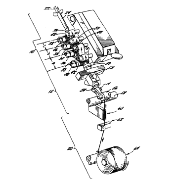
Brief Descri~ti~n of the Draws ~g,~
FIG. 1 is a perspective view of a drafting and
spinning zone according to the present invention;
FIG. 2 is a side plan view of a drafting zone
according to the invention;
FIG. 3 is a microscopy photograph of an air-jet
spun yarn produced according to the present invention;
FIG. 4 is a microscopy photograph of an air-jet
spun yarn produced according to the conventional method
of drawing sliver to form yarn; and
FIGS 5, 6 and 7 are charts respectively comparing
minimum strength, mean strength and certain types of
defects among yarns formed conventionally, those formed
according to the four-pair technique, and those formed
according to the intermediate-pair technique.
Detailed Description of the Invention
FIG. 1 illustrates a drafting and spinning
apparatus according to the invention. As shown in FIG.
CA 02286735 1999-10-15
WO 98/48088 PCTIUS98107854
1, the drafting and spinning apparatus may be divided
into a drafting zone 10, a spinning zone 15, and a
take-up zone 20.
In the operation of the drafting and spinning
apparatus of the invention, a sliver 22 of staple
fibers is advanced to the drafting zone 10. The sliver
22 may be processed prior to entering the drafting zone
using otherwise conventional steps such as opening,
blending, cleaning, carding and combing to provide the
10 desired characteristics in the sliver for drafting and
spinning. The sliver 22 used in the invention
comprises one or more types of staple fibers, each
staple fiber type having a predetermined effective
fiber length.
The present invention is based on increased
knowledge of the relationship of the effective fiber
length to draft roll spacings. The " effective" fiber
length can be defined as the mean decrimped fiber
length of the fiber component prior to use in the
sliver 22. The mean decrimped fiber length can be
determined by fiber array testing of the fibers as
described in ASTM method D-5103. However, staple fiber
is very difficult to decrimp manually for ASTM D-5103.
To ensure a more accurate determination of the
effective fiber length, measurement of three-process
drawn sliver containing 100 of the fiber to be studied
is recommended.
For sliver blended with two fiber types with
different length distributions, one should examine the
appropriate portion of the third pass sliver length
distribution which represents the longest fiber type
CA 02286735 1999-10-15
WO 98/48088 PCTILTS98107854
_g_
present. For example, a blend of 50% nominal 1.5 inch
Fortrel~ polyester and 50% cotton three-process drawn
sliver was examined. As known to those in this art,
the actual length of any given fiber can differ
slightly from its nominal length based on a number of
factors.
To determine the effective fiber length in the
sliver, the upper quartile length (i.e., the length for
which 75% of the fibers are shorter and 25% are longer)
l0 was chosen. This length was selected because the
cotton length distribution differs enough from the
polyester length distribution to make a " mean" fiber
length of the blend somewhat meaningless. Thus
determining the mean length of the polyester portion of
the sliver requires measuring the upper quartile length
of the blend.
It will also be understood that blends that are
the same composition by weight can, of course, differ
in effective fiber length in one or more of the
components of the blend. Nevertheless, those skilled
in the art will be able to make similar selections for
length measurement and without undue experimentation
based on the nominal length of polyester or the type of
cotton present in any particular blend, both which are
generally known or indeed selected for such blends. it
will be further understood that the goal is the
measurement of the longest fibers in any blend and that
in certain cases the cotton (or other) fibers will be
longer than the polyester fibers.
Once the effective fiber length of the sliver is
determined, a superior yarn is produced through the
CA 02286735 1999-10-15
WO 98148088 PCTlUS98107854
_9_
present invention of adjusting roll spacings to less
than the effective fiber length between the two pairs
of intermediate rolls and to the effective fiber length
between the pair of back rolls and the adjacent pair of
intermediate rolls.
The sliver 22 used in the invention includes one
or more types of staple fibers including cut synthetic
fibers, natural fibers, and blends thereof. Exemplary
types of synthetic fibers include polyesters (e. g.,
polyethylene terephthalate, polytrimethylene
terephthalate), rayon, nylon, acrylic, acetate,
polyethylene, polyurethane and polyvinyl fibers.
Exemplary types of natural fibers include cotton,
linen, flax, rayon, lyocell, viscose rayon, cellulose
acetate, wool, ramie, alpaca, vicuna, mohair, cashmere,
guanaco, camel, llama, fur and silk fibers.
Preferably, the staple fibers used in the invention are
polyester (polyethylene terephthalate) fibers, either
alone, or blended with cotton fibers. For example, the
sliver may consist of between about 20o and 100
polyester fibers and between about 80o and 0% cotton
fibers. Typically, the polyester fibers have a cut
length of between about 1.25 inches and 2.0o inches,
preferably between 1.25 inches and 1.60 inches and a
denier per filament of between about 0.5 and 2.5,
preferably, between 0.7 and 1.5. The polyester fibers
used in the sliver 22 preferably have high cohesion for
use in the drawing and spinning apparatus of the
invention. The high cohesion of the polyester fibers
may be achieved by any suitable means known in the art
such as the application of liquid finishes to the
CA 02286735 1999-10-15
WO 98/48088 PCTIUS98/07854
-10-
polyester fibers.
As shown in FIG. 1, the sliver 22 is advanced
through a trumpet guide 24 which gathers the staple
fibers together and then to a series of drafting roll
pairs. The series of drafting roll pairs includes a
pair of back rolls 26 and 28; at least one pair of
intermediate rolls (FIG 1 illustrates two pairs at 30
and 32, and 34 and 36); and a pair of front rolls 38
and 40. Preferably, as shown 15 in FIG. 1, the pair of
intermediate rolls 34 and 36 adjacent the pair of front
rolls 38 and 40 is a pair of apron rolls. For use in
the invention, the series of drafting rolls preferably
consists of at least four pairs or drafting rolls as,
for example, the four roll pair arrangement illustrated
in 20 FIG. 1. Nevertheless, the invention may also be
applied to three roll pair arrangements having only one
intermediate pair of drafting rolls.
The pairs of drafting rolls in the drafting zone
10 operate such that the speeds of the roll pairs
increase in the direction of sliver movement as
indicated, e.g., by directional arrow A, thereby
drafting the sliver 22 down to yarn size. As
illustrated in FIG. 1, typically the top roll 26, 30,
34 and 38 in the roll pair, rotates in a direction
opposite that of the bottom roll 28, 32, 36 30 and 40
in the roll pair. As is well known to those skilled in
the art, the ratio between the weight or length of the
sliver 22 fed into the drafting zone IO and the weight
or length of the sliver exiting the drafting zone is
known as the draft ratio. The draft ratio may also be
measured across individual roll pairs such as the back
CA 02286735 1999-10-15
WO 98/48088 PCTIUS98I07854
-11-
draft (between the back rolls and the intermediate
rolls), the intermediate draft (between the
intermediate rolls and the apron rolls), and the main
draft (between the apron rolls and the front rolls).
Preferably, in the present invention, the overall draft
ratio is between about 50 and about 220, and more
preferably between about 130 and about 200. Typically,
the majority of drafting occurs in the main draft. The
width of the sliver 22 and thus the draft ratio may be
affected by the speeds selected for the drafting rolls
or a sliver guide (not shown) located between adjacent
rolls pairs such as intermediate roll pairs 30 and 32,
and 34 and 36. In the drafting zone 10, the distances
between adjacent roll pairs or nips are typically
IS preset depending on numerous factors including the
staple fiber length, break draft and fiber cohesive
forces. As illustrated in FIGS. 1 and 2, the distances
between adjacent nips 42 (for the front roll pair), 44
(for the apron roll pair}, 46 (for the intermediate
roll pair) and 48 (for the back roll pair) are a, b and
c, respectively. The distance between nips may be
fairly approximated by averaging the distance between
adjacent top rolls and the distance between
corresponding adjacent bottom rolls. For example, if
the spacings (FIG. 2) between adjacent top rolls are
d=48 mm, e=37 mm, and f=35 mm, respectively, and 25 the
spacings between bottom rolls are g=44 mm, h=35 mm and
i=35 mm, respectively, than the distances a, b and c,
between adjacent nips would be a=46 mm, b=36 mm and
c=35 mm. respectively. In addition to the roll
spacings, various diameters for the drafting rolls may
CA 02286735 1999-10-15
WO 98/48088 PCT/US98/07854
-12-
be selected for use in 30 the invention and larger
diameter rolls may be selected to further increase
contact with the sliver 22 and thus increase the
quality of the resulting spun yarn.
The conventional wisdom regarding roll spacing for
a drafting zone 10 has been to set the distance between
nips in adjacent drafting roll pairs to a distance
greater than the staple fiber length to prevent
individual fibers from bridging adjacent pairs of
drafting rolls and breaking. It has now been
discovered, however, that narrowing the distance
between the nip 48 of the back rolls and the nip 46 of
the adjacent intermediate rolls and the distances
between the nips of adjacent intermediate rolls (e. g.,
46 and 44) to no more than~the effective fiber length
of the longest fiber type in the sliver 22 results in
spun yarns having greater uniformity and mechanical
properties, particularly for high-speed spinning
processes (i.e., 150 meters/minute?. For example, if
the sliver 22 consists of 80% cotton fibers having an
effective fiber length of 1.0 inch and 20% polyester
fibers having an effective fiber length of 1.5 inches,
then the distances b and c would be no more than 1.50
inches (38 mm?, and may be 36 mm and 37 mm,
respectively. The longest fiber type in the sliver 22
refers to the fiber type having the longest effective
fiber length and forming a substantial portion of the
sliver 22. Stated differently, fiber types which do
not constitute a significant portion of the sliver are
not used to determine the longest fiber type in the
sliver and thus the roll spacing in the drafting zone
r ~.
CA 02286735 1999-10-15
WO 98148088 PCT/US98/07854
-13-
10.
.Although not wishing to be bound by a particular
theory, it is believed that roll spacings tighter than
the effective fiber length of the longest fiber type in
the sliver 22 in the break and intermediate draft zones
reduce fiber slippage at each nip point and thereby
increase drafting control on the sliver. This greater
control increases fiber alignment and uniformity in the
drafted sliver 22 as it is introduced to the front
drafting zone. A high cohesion sliver is preferred
because it is believed to prevent fibers from slipping
under the higher drafting force generated by the
tighter roll spacings. Because the sliver 22 entering
the front drafting zone is highly uniform and aligned
because of the tighter roll spacings, the sliver 22
exits the front roll nip even more uniform and aligned.
Accordingly, the more uniform and aligned sliver
entering the spinning zone 15 creates a unique spun
yarn. Upon examination of the spun yarns through
microscopy, more wrapper fibers appear to be generated
in this yarn (FIG. 3) at the same spinning conditions
than with yarn produced from sliver drafted with the
conventional wider roll spacings in the back and
intermediate drafting zones (FIG. 4). It is believed
that the number and frequency of the wrapper fibers
increase because of the greater fiber alignment in the
sliver 22. The greater number of wrapper fibers
combined with the more uniform and aligned sliver going
into the spinning zor_e is believed to create a spun
yarn with increased strength and reduced quality
defects. Furthermore, the improvements in the yarn may
CA 02286735 1999-10-15
WO 98/48088 PCTIUS98/07854
-14-
result in improvements in the weaving performance of
the yarn and the potential use of yarns, specifically
air-jet yarns, in some knit applications. In addition
to the above, it is believed that the speed and the
mass of the sliver 22 used in the drafting zone 10 may
contribute to the benefits of the invention. By way of
example, in four-roll systems used according to the
invention, the speed in the break and intermediate
draft zones is about 3 times faster at the second nip
roll than in ring spinning draft systems. The mass of
the sliver 22 entering the drafting zone 10 is also
typically 2 times greater than the roving entering a
typical ring spinning draft system. The combination of
greater speed and fiber mass is believed to make fiber
slippage at the nip points more likely in the higher
speed four-roll drafting system (e. g., MJS drafting
system) thus providing the benefits of the invention in
the higher speed four-roll system and not in ring
spinning systems.
Once the sliver 22 exits the drafting zone 10, it
is advanced to the spinning zone 15. The spinning
apparatus in the spinning zone 15 selected for use in
the present invention operates at higher speeds than
associated with ring spinning. Exemplary spinning means
which operates at these speeds and which use roller
drafting systems include air-jet spinning means and
roller jet spinning means. Generally, the spinning
means operates at a take-up speed cf greater than about
150 meters/minute, preferably, of greater than about
190 meters/minute and more preferably, of greater than
about 220 meters/minute. The spinning apparatus is
~ ~
CA 02286735 1999-10-15
WO 98/48088 PCT/US98I07854
-15-
typically capable of producing yarns having counts
between 9 and 50, preferably 26 and 42. An exemplary
spinning apparatus is an air-jet spinning apparatus
such as the MJS 802H spinning apparatus is from Murata
Machinery Limited.
FIG. 1 illustrates an air-jet spinning apparatus
for use in the invention. In the spinning zone 15, the
sliver 22 enters a jet spinner 50 and air nozzle 52
wherein the drafted sliver is twisted by opposing air
vortices to form a yarn 54.
The spun yarn 54 is then advanced to the take-up zone
and specifically, to a pair of delivery rolls 56 and
58. The spinning zone 15 also includes a slack tube 60
to hold any accumulated fiber during the start-up of
15 the drafting and spinning apparatus. The yarn 54 is
then cleared by a yarn clearer 62 and collected on a
take-up roll 64.
As described above, the spun yarn produced
according to the invention has high uniformity and
20 improved mechanical properties over conventional yarns
produced according to conventional constructions having
broader roll spacing.
Specifically, the spun yarn produced according to the
invention has increased strength and reduced defects
over conventional yarns formed using broad roll
spacing. The benefits of the present invention will
now be further illustrated by the following non-
limiting example.
EXAMPLE lA AND COMPA_RATTVF E~pLES 1B and 1C
Two slivers consisting of two cut length
variations of intimately blended 50°s 0.9 denier per
CA 02286735 1999-10-15
WO 98/48088 PCT/US98107854
-16-
filament FORTREL~ Type 510 polyester (available from
Wellman, Inc.) and 50~ cotton stable fibers were
advanced through a four roll drafting zone and spun
using an MJS 802H air-jet spinner from Murata Machinery
Limited with an H3 air nozzle at a speed of 273
meters/minute. The air-jet spinning apparatus was
preset at a feed ratio of 0.98, a condenser setting of
3 mm, an apron spring tension of 3 kg, a Nozzle 1 (N1)
to front roll distance 10 of 39.0 mm, a N1 pressure of
2.5 kgf /CM2 and a Nozzle 2 (N2) pressure of 5 kgf
/CM2. The effective fiber length of the 35 gr/yd three-
process drawn slivers were measured using ASTM D-5103.
The upper quartile length of the slivers, representing
the mean decrimped length of the polyester fiber in
each sliver, was 38 and 39 mm respectively. The
polyester fibers had high cohesion through the use of
liquid finishes and for these particular samples the
Rothschild cohesion of the sliver was 182 cN for both
variants. The yarn count of the spun yarn was measured
at 37 Ne. In Example lA, a narrow roll spacing was
selected according to the invention wherein the top
roll spacings were preset at 48 mm, 37.5 mm, and 39 mm
(d, a and f, respectively, in FIG. 2) and the bottom
roll spacings were preset at 44 mm, 39 mm and 38 mm (g,
h and i, respectively, in FIG. 2). The distances
between the nips were 46 mm, 38.25 mm and 38.5 mm (a, b
and c, respectively in FIG. 2). The draft ratio across
the drafting zone was 155 consisting of a break draft
of 2.0, an intermediate draft of 2.17 and a main draft
of 36. The sliver used for example lA had a 39 mm
effective fiber length in order to be slightly longer
CA 02286735 1999-10-15
WO 98/48088 PCT/US98107854
-17-
than the 38.25 mm intermediate drafting zone. In
Comparative Examples 1B and 1C, sliver exhibited an
effective fiber length of 38 mm. In Comparative
Example 1B, narrow roll spacings such as those
presented in parent application 08/844,463 were
utilized. The top roll spacings were preset at 48 mm,
36 mm, and 36 mm (d, a and f, respectively, in FIG. 2)
and the bottom roll spacings were preset at 44 mm, 37
mm and 36 mm (g, h and i, respectively, in FIG. 2).
The distances between the nips were 46 mm, 36.5 mm and
36 mm (a, b and c, respectively in FIG. 2). In
Comparative Example 1C, a broad roll spacing such as
those conventionally used in the art was selected
wherein the top roll spacings were preset at 48 mm, 39
mm, and 42 mm (d, a and f, respectively, in FIG. 2) and
the bottom roll spacings were preset at 44 mm, 41.5 mm
and 42 mm (g, h and i, respectively, in FIG. 2). The
distances between the nips were 46 mm, 40.25 mm and 42
mm (a, b and c, respectively in FIG. 2). The draft
ratio used was the same for Examples lA, 1B, and 1C.
The yarns produced in Example lA and Comparative
Examples 1B and 1C were tested for mechanical
properties and uniformity. The mechanical properties
of the yarns were tested using both a Statimat testing
apparatus at 100 breaks and a Tensojet testing
apparatus at 6000 breaks and the yarn quality was
determined using a Uster 3 Evenness Tester for ,000
yards and a Classimat II device for 100,000 me~ers.
The results are provided in TABLE l, and the Statimat
Minimum Strength, Statimat Mean Strength, and Classimat
H-1 Defects are also plotted in Figures 5, 6 and 7
CA 02286735 1999-10-15
WO 98!48088 PCT/US98/07854
-18-
respectively.
Sample Number lA 1B 1C
Effective fiber length (mm) 39 38 38
MJS Top Roll Spacings (mm) 48-37.5-39 48-39-42 48-36-36
MJ5 Bottom Roll Spacings (mm) 44-39-38 44-41.5-42 44-37-36
Statimat Data (100 breaks)
Yarn Count (Ne) 37.07 37.76 36.89
Mean Tenacity (gf/den) 1.83 1.72 1.81
Second Lowest Tenacity (gf/den) 1.45 1.3 1.36
Minimum Tenacity (gf/den) 1.33 1.06 1.24
Mean Single-End Strength (gf) 262 242 261
Single-End Strength CV (%) 10.6 11.0 12.2
Maximum Strength (gf) 320 294 346
Minimum Strength (gf) 192 149 179
Mean Single-End Elongation (%) 8.3 7,9 7.8
Elongation CV% 8.1 10.1 8.0
Maximum Elongation (%) 9.8 9,9 9,1
Minimum Elongation (%) 6.7 6.1 6.0
Tensojet Data (6000 breaks)
Mean Tenacity (gf/den) 1.91 1.78 1.90
Lowest l% Tenacity (gf%den) 1.40 1.28 1.25
Lowest 0.1% Tenacity (gf/den) 1.20 1.10 0.98
Mean Single-End Strength (gf) 275 251 273
Single-End Strength CV (%) 10.8 10.9 13.8
Maximum Strength (gf) 376 351 430
Lowest 1.0% Strength (gf) 200 180 180
Lowest 0.1% Strength (gf) 172 155 142
Minimum Strength (gf) 148 141 136
Mean Single-End Elongation (%) 8.1 7.5 7.5
Maximum Elongation (%) 10.7 10.0 9.9
Lowest 0.1% Elongation (%) 5.6 4.6 4.8
Minimum Elongation (%) 5.2 3.9 4.2
tester 3 Yarn Evenness Data
Uster Evenness (CV%) 18.1 18.6 18.6
Uster 1 yd Evenness (CV%) 6.3 6.1 7.3
Uster 3 yd Evenness (CV%) 3.8 3.7 4.5
Uster 10 yd Evenness (CV%) 2.2 2.2 2.3
IPI Thin Places (-50%) 95 134 134
IPI Thick Places (+50%) 517 615 483
IPI Neps (+200%) 1335 1269 1520
Total IPI's 1947 2018 2137
Classimat Data
A-1 Defects (A1-A2-A3-A4) 1396 1567 1344
Major Defects (A4+B4+C3+C4+D3+D4)B 1 C
H-1 Defects 823 527 1918
H-2 Defects ~ 4 ~ 0 15
i.
CA 02286735 1999-10-15
WO 98/48088 PCT/US9S/07854
-19-
I-1 Defects 8 3 43
I-2 Defects 0 0 3
Long Thicks (E+F+G) 3 1 9
Total Defects 2242 2099 3332
Card Sliver Rothschild Cohesion 664 651 651
(cN) 182 182 182
Third Pass Rothschild Cohesion
(cN)
As shown in TABLE 1, the 50/50 polyester and
cotton blends of the invention Example lA have a 10~
average increase in mean Tensojet single-end strength,
a 11% average increase in lowest O.lo Tensojet
strength, and a 4~ average reduction in the number of
total defects, compared to the 50/50 blends prepared by
conventional methods in Example 1B. The 50/50 spun
yarn has a mean Tensojet single-end strength of greater
than 275 gf and less than 2000 total defects per 1000
yards. The total Uster defects per 1000 yards include
the number of peps and the number of thick and thin
defects in the yarn per 1000 yards. As noted in TABLE
1, a " nep" defect refers to a yarn portion at least
200% thicker than average, a "thick" defect refers to a
yarn portion at least 50% thicker than average, and a
"thin" defect refers to a yarn portion 50~ thinner than
average. In addition to these properties, the yarn has
a mean Tensojet tenacity of more than 1.91 gf/den, a
maximum strength of greater than about 376 gf, and a
minimum strength of greater than about 148 gf, each of
which are improvements over conventionally produced
50/50 yarn.
Furthermore, a comparison of Examples lA and 1C
show the improvements of the intermediate-pair
technique even above those of the four-pair technique.
The 50/50 polyester and cotton blends of the invention
CA 02286735 1999-10-15
WO 98/48088 PCTIUS98/07854
-20-
Example 1A have a comparable mean Tensojet single-end
strength to Example 1C. However, the current invention
exhibits an 21°s average increase in lowest 0.1~
Tensojet strength, a 9o average reduction in the number
of total Uster defects, and a 33~ average reduction in
the number of total Classimat defects. The total
Classimat defects per 100,000 meters includes several
classifications of thin and thick places.
The less favorable results for Lowest 0.1~
l0 Strenght for Example 1C (Tensojet Data) are somewhat
unexpected, but may result from the individual
characteristics of the particular spinning machinery
used.
As illustrated by the Classimat Data (Table 1;
FIG. 7) yarns produced according to the invention tend
to have slightly higher total Classimat defects than do
the control yarns. Nevertheless, the difference tends
to be minimal, especially when considered in light of
the advantages of the novel yarns.
The visible quality of the yarns of the
intermediate roll technique is comparable to that of
the four-pair technique. As illustrated in FIG. 3 (a
microscopy photograph of the conventional yarn of
Comparative Example 6) and FIG. 4 (a microscopy
photograph of the yarn of Example 6 according to the
present invention), the yarns of the invention have a
visibly superior quality over the conventionally
produced yarns. Although not wishing to be bound by a
particular theory, it is believed that because of the
increased control in the drafting zone of the
invention, the wrapper fibers are twisted more
CA 02286735 1999-10-15
WO 98!48088 PCTIUS98/07854
-21-
frequently around the core fibers; i.e., have a sharper
wrapping angle and more wraps per unit length. The
resulting improvement in visible quality may be
responsible for the decreased defects in the yarn and
may also be responsible for the increased mechanical
properties of the yarns of the invention.
Although the four-pair technique offers these
advantages, significantly more machine modification is
required which adds a presently significant cost factor
to the machinery. In particular, moving the drafting
rolls to match the relationships in the four-pair
teachnique tends to require a large number of
adjustments to make things fit. Spring housings must
be modified and a different condenser and condenser
bracket must be utilized.
Accordingly, in the intermediate-pair technique
the distance between the bottom intermediate roll pairs
is set to 39 mm so that the aforementioned machine
modifications are not required. Thus, in this
embodiment of the invention a sliver with fibers of a
longest effective length of 39 millimeters was used in
a four roll system in which the distance between nips
was set at 38.5 millimeters between the back rolls and
the first set of intermediate rolls, at 38.25
millimeters between the nips of the intermediate rolls
and at 46 millimeters between second intermediate roll
pair and the front roll pair.
Stated differently, in the intermediate-pair
technique only the intermediate drafting zone has a nip
to nip distance that is longer than the effective fiber
length. Preferably, the back zone is also maintained
CA 02286735 1999-10-15
WO 98!48088 PCTIUS98/07854
-22-
near, but slightly less than, the effective fiber
length.
It has been further discovered that the strength
and quality of yarns produced in the intermediate-pair
technique is greater than those produced in the four-
pair technique.
In the intermediate-pair technique, the back zone
is now comparable to the effective fiber length, the
intermediate zone is still shorter than the effective
to fiber length, and a slightly longer stable fiber is
preferably used in the process.
With respect to the difference in side plate
spacing from conventional spacing, a comparative side
plate on the four mentioned MJS spinning machines would
include nip spacing of 42 millimeters in the back zone,
40.25 millimeter in the intermediate zone, and 46
millimeters in the front drafting zone. Thus, as Table
2 illustrates, it tends to be mechanically easier to
adjust the side plates to take advantage of the
intermediate-pair technique as opposed to adjusting the
side plates to take advantage of the four-pair
technique.
TABLE 2
Drafting process Front Intermediate Hack
versus Nip Spacing
Conventional 46 40.25 42
'463 Application 1 46 36.5 36
Invention 48 38.25 38.5
At present cost structures, applicants estimate that
modifying a typical side plate in an air jet spinning
~ ~ .
CA 02286735 1999-10-15
WO 98/48088 PCTIUS98107854
-23-
machine in the manner disclosed in the intermediate-
pair technique is approximately 1/6'h the cost of the
modifications required for the four-pair technique.
It thus appears that in the back drafting zone the
most favorable results are obtained when the nip
distance is approximately equal to the fiber length
while in the intermediate zone the most favorable
results are obtained when the nip is shorter than the
fiber length.
Although not yet formally demonstrated, it appears
that the advantages will likewise extend to other high
speed spinning machines such as Vortex type machines
that create true twists in an entire yarn.
Again, although applicants do not wish to be bound
by any particular theory, it thus appears that the
intermediate drafting zone is the most important in
terms of yarn strength in these high speed spinning
systems. Apparently, the closer the fiber length
approaches the nip spacing in the intermediate zone,
the higher the drafting force will be on the sliver.
Additionally, the intermediate zone is the lowest
drafting ratio zone of the entire system. Thus, it
appears that the high drafting force in the
intermediate zone results in very good alignment.
Set forth in progressive fashion, the nip spacing
of the present invention produces a high drafting force
in the intermediate zone which in turn produces a
better alignment among the staple fibers in the yarn.
In turn, the enhanced alignment results in fewer thin
places in the yarn and thus a more uniform bundle. In
turn, the more uniform bundle produces a tighter wrap
CA 02286735 1999-10-15
WO 98/48088 PCTlUS98/07854
-24-
during air jet spinning which results in the stronger
yarn observed.
Although the above description generally applies
to high speed spinning processes, particularly air-jet
spinning processes, it will be understood that the
invention is not limited thereto since modifications
may be made by those skilled in the art, particularly
in light of the foregoing description. Therefore, said
modifications and embodiments are intended to be
included within the spirit and scope of the following
appended claims.