Language selection

Search

Patent 2286740 Summary

Third-party information liability

Some of the information on this Web page has been provided by external sources. The Government of Canada is not responsible for the accuracy, reliability or currency of the information supplied by external sources. Users wishing to rely upon this information should consult directly with the source of the information. Content provided by external sources is not subject to official languages, privacy and accessibility requirements.

Claims and Abstract availability

Any discrepancies in the text and image of the Claims and Abstract are due to differing posting times. Text of the Claims and Abstract are posted:

  • At the time the application is open to public inspection;
  • At the time of issue of the patent (grant).
(12) Patent: (11) CA 2286740
(54) English Title: SELF-DRILLING AND THREAD-FORMING CONNECTING ELEMENT
(54) French Title: ELEMENT DE FIXATION AUTOPERFORANT ET AUTOTARAUDEUR
Status: Deemed expired
Bibliographic Data
(51) International Patent Classification (IPC):
  • F16B 25/10 (2006.01)
  • F16B 35/04 (2006.01)
(72) Inventors :
  • DICKE, ROBERT (Germany)
(73) Owners :
  • A-Z AUSRUSTUNG UND ZUBEHOR GMBH & CO. KG (Germany)
(71) Applicants :
  • A-Z AUSRUSTUNG UND ZUBEHOR GMBH & CO. KG (Germany)
(74) Agent: SMART & BIGGAR
(74) Associate agent:
(45) Issued: 2004-06-08
(86) PCT Filing Date: 1998-04-14
(87) Open to Public Inspection: 1998-10-22
Examination requested: 2000-08-11
Availability of licence: N/A
(25) Language of filing: English

Patent Cooperation Treaty (PCT): Yes
(86) PCT Filing Number: PCT/EP1998/002164
(87) International Publication Number: WO1998/046891
(85) National Entry: 1999-10-15

(30) Application Priority Data:
Application No. Country/Territory Date
297 06 749.4 Germany 1997-04-15

Abstracts

English Abstract


The present invention relates to a
self-drilling and thread-forming connecting element, in
particular a screw (1), having a threaded shank (2) and
a drilling point (4) at the end for the chip-forming
drilling of a core hole for the threaded shank (2). The
drilling point (4) is designed as a step drill having
at least two drilling steps (6, 8) with different
diameters (D1, D2).


French Abstract

La présente invention porte sur un élément de fixation autoperforant et taraudeur, en particulier une vis (1) dotée d'une tige filetée (3) et d'une extrêmité en forme de pointe perforeuse (4) pour percer un avant-trou par enlèvement de matière, destiné à la tige filetée (2). La pointe perforeuse (4) est conçu comme un foret étagé comprenant au moins deux étages (6, 8) de diamètres différents (D1, D2).

Claims

Note: Claims are shown in the official language in which they were submitted.


CLAIMS:

1. A self-drilling and thread-forming fastener comprising:

a screw extending along a longitudinal axis and having a threaded shank
portion and a drilling point located at generally opposite longitudinal ends
thereof;

said drilling point comprising a first drilling step of a first diameter and a
second drilling step of a second diameter, each said drilling step having a
first cutting
edge and a second cutting edge, said first and second cutting edges being
symmetrical
about said longitudinal axis;

said first and second cutting edges of said first drilling step defining a
first
cutting angle of less than 180 degrees and said first and second cutting edges
of said
second drilling step defining a second cutting angle of less than 180 degrees;

wherein said first and second cutting edges of said first drilling step merge
into said first and second cutting edges of said second drilling step at first
and second
transition edges, each said transition edge extending perpendicularly from one
of said
first and second cutting edges of said first drilling step to one of said
first and second
cutting edges of said second drilling step, said first and second transition
edges each
extending obliquely relative to said longitudinal axis.

2. ~The self-drilling and thread forming fastener according to claim 1,
wherein said
first cutting angle and said second cutting angle are equal.

3. ~The self-drilling and thread forming fastener according to claim 1,
further
comprising:

a flute located in front of said cutting edges as determined by the direction
of
forward rotation of said fastener.

Description

Note: Descriptions are shown in the official language in which they were submitted.


CA 02286740 1999-10-15
8341/VII/bu
A-Z Ausrustung and Zubehor GmbH & Co. KG
Ruhrallee 1-3, D-45525 Hattingen
Self-drilling and thread-forming connecting element
The present invention relates to a self-
drilling and thread-forming connecting element, in
particular a screw, having a threaded shank and a
drilling point at the end for the chip-forming drilling
of a core hole for the threaded shank.
Such screws are known, which drill a core hole
themselves in the respective material with a chip
forming action by means of their drilling point, and
the screw is subsequently screwed into this core hole
with the threaded shank like a sheet-metal screw. In
the process, a corresponding internal thread forms
automatically. To this end, the diameter of the core
hole is designed to be correspondingly smaller in
adaptation to the design of the thread on the threaded
shank, so that a thread can be formed automatically in
the core hole.
The object of the invention is to provide such
a connecting element in which the drilling behaviour,
in particular the initial spot drilling, during the
drilling of the core hole is improved.
According to the invention, this is achieved in
that the drilling point is designed as a step drill
having at least two drilling steps with different dia
meters. By this design according to the invention, the
first drilling step, which has a drilling point at the
end, can be designed with regard to its cutting
geometry specifically for good spot-drilling behaviour,

CA 02286740 1999-10-15
- 2 -
whereas the second, axially adjoining drilling step
serves to continuously drill out the core hole and can
have a cutting geometry specifically designed for this
purpose. Thus, in particular, different cutting angles
may be provided, in which case preferably the cutting
angle of the first drilling step, in order to ensure
good spot-drilling behaviour, may be- designed to be
smaller (more acute) than the cutting angle of the
second drilling step.
As a result, the connecting element according
to the invention is also especially well suited for
direct drilling and screwing into sheet-metal materials
by virtue of the fact that, by a suitable design, the
sheet rolling skin, which as a rule is relatively hard
or tough, can be destroyed by the first step.
Further advantageous design features of the
invention are contained in the subclaims and in the
following description.
Although step drills as such are known per se
in tool technology, the transfer of these measures to a
connecting element of the generic type is not obvious,
since such a step drill is a mass-produced article. The
person skilled in the art will therefore not readily
apply such a measure, which indeed is relatively
complicated at first glance, to a connecting element of
the type in question here.
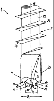
The invention is to be explained in more detail
with reference to a preferred exemplary embodiment
shown in the drawing. In the drawing, the single figure
shows the point-side end section of a connecting
element according to the invention.
Partly illustrated by way of example in the
drawing as a connecting element is a screw 1, which has
a threaded shank 2 and a drilling point 4 at the end.
In addition, the screw l, on the other side, may have a
screw head (not shown) having any desired slot or such
like application point for a rotary tool. However, the
connecting element may also be designed, for example,
without a head as a threaded stud or the like.

CA 02286740 1999-10-15
- 3 -
According to the invention, the drilling point
4 is designed as a step drill having at least two
drilling steps 6, 8, which are arranged axially one
behind the other and have different diameters D1, Dz.
The first drilling step 6 at the end has a spot-
drilling point 10.
Each drilling step 6, 8 comprises (at least)
two cutting edges 12 and 14 respectively, which define
a certain cutting angle a and (3 respectively. The
cutting edges 12 of the first drilling step 6 enclose a
cutting angle a,, whereas the cutting edges 14 of the
second drilling step 8 define a cutting angle (3. In the
exemplary embodiment shown, the cutting angles a and ~i
are dimensioned to be approximately the same size, but
they may also be different. The cutting angle a of the
first drilling step 6 is then preferably smaller than
the cutting angle (3 of the second drilling step 8.
The cutting edges 12 of the first drilling step
6 merge into the cutting edges 14 of the second
drilling step 8 via transition edges 16. In this case,
the transition edges 16, starting from the cutting
edges 12 of the first drilling step 6, preferably run
obliquely inwards with a certain undercut up to the
cutting edges 14 of the second drilling step 8. If need
be, however, the transition edges 16 run parallel to
one another and to the longitudinal axis 18 of the
screw 1. Thus the region of the transition edges 16 has
no separate chip-forming drilling action.
In the exemplary embodiment shown, the
transition edges 16 run approximately at right angles
to the cutting edges 12, 14 of the drilling steps 6, 8.
Furthermore, it can be seen from the drawing
that a common, approximately axially running flute 20
is in each case located in front of the cutting edges
12, 14 in the direction of rotation.
The screw 1, at least in the region of the
drilling point 4, but preferably also in the region of
the threaded shank, is made of a hardened, highly
carburized steel.

CA 02286740 1999-10-15
- 4 -
Finally, it may also be mentioned that the
threaded shank 2 consists of an essentially cylindrical
shank 22, i.e. a shank which is circular in diameter,
and which has a single- or mufti-start thread 24 formed
as a helically running prominence.
The invention is not restricted to the
exemplary embodiments shown and described but also
comprises all embodiments having the same effect within
the scope of the invention.

Representative Drawing
A single figure which represents the drawing illustrating the invention.
Administrative Status

For a clearer understanding of the status of the application/patent presented on this page, the site Disclaimer , as well as the definitions for Patent , Administrative Status , Maintenance Fee  and Payment History  should be consulted.

Administrative Status

Title Date
Forecasted Issue Date 2004-06-08
(86) PCT Filing Date 1998-04-14
(87) PCT Publication Date 1998-10-22
(85) National Entry 1999-10-15
Examination Requested 2000-08-11
(45) Issued 2004-06-08
Deemed Expired 2018-04-16

Abandonment History

There is no abandonment history.

Payment History

Fee Type Anniversary Year Due Date Amount Paid Paid Date
Application Fee $150.00 1999-10-15
Registration of a document - section 124 $100.00 2000-02-28
Maintenance Fee - Application - New Act 2 2000-04-14 $50.00 2000-04-12
Request for Examination $200.00 2000-08-11
Maintenance Fee - Application - New Act 3 2001-04-16 $50.00 2001-03-15
Maintenance Fee - Application - New Act 4 2002-04-15 $100.00 2002-03-14
Maintenance Fee - Application - New Act 5 2003-04-14 $150.00 2003-02-07
Maintenance Fee - Application - New Act 6 2004-04-14 $200.00 2004-03-11
Final Fee $300.00 2004-03-23
Maintenance Fee - Patent - New Act 7 2005-04-14 $200.00 2005-02-24
Maintenance Fee - Patent - New Act 8 2006-04-14 $200.00 2006-02-21
Maintenance Fee - Patent - New Act 9 2007-04-16 $200.00 2007-03-08
Maintenance Fee - Patent - New Act 10 2008-04-14 $250.00 2008-03-07
Maintenance Fee - Patent - New Act 11 2009-04-14 $250.00 2009-03-16
Maintenance Fee - Patent - New Act 12 2010-04-14 $250.00 2010-03-19
Maintenance Fee - Patent - New Act 13 2011-04-14 $250.00 2011-03-09
Maintenance Fee - Patent - New Act 14 2012-04-16 $250.00 2012-03-21
Maintenance Fee - Patent - New Act 15 2013-04-15 $450.00 2013-03-19
Maintenance Fee - Patent - New Act 16 2014-04-14 $450.00 2014-03-12
Maintenance Fee - Patent - New Act 17 2015-04-14 $450.00 2015-04-09
Maintenance Fee - Patent - New Act 18 2016-04-14 $450.00 2016-03-23
Owners on Record

Note: Records showing the ownership history in alphabetical order.

Current Owners on Record
A-Z AUSRUSTUNG UND ZUBEHOR GMBH & CO. KG
Past Owners on Record
DICKE, ROBERT
Past Owners that do not appear in the "Owners on Record" listing will appear in other documentation within the application.
Documents

To view selected files, please enter reCAPTCHA code :


To view images, click a link in the Document Description column. To download the documents, select one or more checkboxes in the first column and then click the "Download Selected in PDF format (Zip Archive)" or the "Download Selected as Single PDF" button.

List of published and non-published patent-specific documents on the CPD .

If you have any difficulty accessing content, you can call the Client Service Centre at 1-866-997-1936 or send them an e-mail at CIPO Client Service Centre.


Document
Description 
Date
(yyyy-mm-dd) 
Number of pages   Size of Image (KB) 
Representative Drawing 1999-12-03 1 7
Abstract 2003-11-06 1 10
Claims 2003-11-06 1 36
Abstract 1999-10-15 1 14
Description 1999-10-15 4 147
Claims 1999-10-15 2 48
Drawings 1999-10-15 1 18
Cover Page 1999-12-03 1 34
Representative Drawing 2004-05-04 1 8
Cover Page 2004-05-04 1 35
Correspondence 1999-11-19 1 2
Assignment 1999-10-15 3 116
PCT 1999-10-15 13 406
Assignment 2000-02-28 2 74
Prosecution-Amendment 2000-08-11 1 37
Prosecution-Amendment 2000-09-11 2 72
PCT 1999-10-16 5 176
Prosecution-Amendment 2003-05-06 2 59
Prosecution-Amendment 2003-11-06 4 99
Correspondence 2004-03-23 1 34
Correspondence 2006-08-23 3 86
Correspondence 2006-09-14 1 14
Correspondence 2006-09-14 1 20