Note: Descriptions are shown in the official language in which they were submitted.
CA 02286745 1999-10-18
Provisional Application of
Mario Gauthier
and
Jean Saint-Amour
for a:
MODULAR SOLARIUM AND KIT FOR CONSTRUCTING THE SAME
FIELD OF THE INVENTION:
to
The present invention relates to the general field of solariums and is
particularly
concerned with a modular solarium and a kit for constructing the same.
BACKGROUND OF THE INVENTION:
Relatively recent social trends such as so-called "'cocooning" have
concurrently lead to an
increased interest in household comfort related items. One feature which
recently
became increasingly popular is the so-called solarium or sunroom, an extension
formed
primarily of transparent or translucent panels forming a light transmitting
enclosure.
Also, in consideration of new housing prices, many households are constructing
additions
or otherwise remodeling their existing homes to add features which were
unavailable or
unaffordable at purchase rather than purchasing newer homes. In many cases,
the
1
CA 02286745 1999-10-18
owner of the home or property prefers to perform the work him or herself
rather than
incurring the expense of hiring a professional to <io the work.
While this may be feasible in the case of standard construction, specialized
work such as
glazing large panels for a solarium is generally beyond the average handyman.
Thus,
when labor costs are added to the cost of the mal:erials, quite often solarium
additions are
beyond the budget of the home or property owner. Further, because of the great
amount
of labor involved, the construction of conventional solariums takes a
relatively long time,
for example a few days or more even by skilled professionals.
The prior art is replete with various patents disclosing solarium building
kits attempting
to circumvent the hereinabove mentioned problems. However, most prior art
structures
suffer from a set of drawbacks including undue weight creating the need for
costly
foundations, overall mechanical complexity leading to relatively high
production costs
and low reliability. Prior art structures also often suffer from aesthetically
deterring
appearances and overly complex assembly procedures. Accordingly, there exists
a need
for an improved modular solarium and kit for constructing the same.
Advantages of the present invention includes that the proposed structure is
adapted to
2o provide a light transmitting enclosure which facilitates the passage of the
sun's rays into
the enclosure and thereby increases the amount of sunlight and heat collected
within the
latter. Also, the proposed structure is of a modular nature and can be sold as
a kit which
can be readily assembled using easy and ergonomic steps without requiring
special
2
CA 02286745 1999-10-18
tooling or manual dexterity. Further, the proposE;d structure is designed so
as to allow for
customization of its configuration. It may be constructed in a variety of
shapes and sizes
that are esthetically pleasing in appearance.
Still further, once assembled, the proposed solarium is designed so as to form
a
structurally stable structure adapted to withstand harsh environmental factors
such as
strong winds, heavy rain or snowfalls, high temperature differentials and the
like.
Furthermore, the proposed solarium is designed so as to be readily mountable
adjacent
existing structures such as the exterior wall of a conventional household
without
1o substantially altering or damaging the latter.
Also, the proposed structure is designed so as to~ be relatively light weight
thus reducing
the need for foundations or other horizontal vertical support structures.
Indeed, the
proposed structure preferably incorporates translucent or transparent panels
made out of
flexible polymeric material instead of the conventional solarium glass panels
used mostly
in the prior art. The replacement of conventional glass panels by flexible
polymeric
films not only substantially reduces the overall weight of the structure and
potentially
reduces overall manufacturing costs but also provides interesting thermal,
sealing and/or
structural characteristics.
Still further, the proposed structure is provided with a frame having frame
members with
a specifically designed cross-sectional configuration. This specific
configuration
provides a relatively low weight to stability ratio. It also offers
interesting bending
3
CA 02286745 2005-07-26
20
characteristics in a predetermined geometrical plane that facilitates
longitudinal forming
thereof. Also, the profile configuration is designed so as to optimize the
connection
between the transparent or translucent panels attached thereto and its own
integral
connecting sections.
The profile configuration further allows for customized positioning of the
respective
components and the addition of optional add-ons such as sliding windows,
doors, screens
and the Iike. Furthermore, the proposed solarium is adapted to be
manufacturable using
conventional forms of manufacturing thus providing a solarium which will be
economically feasible, long lasting and relatively trouble free.
In accordance with an embodiment of the present invention there is provided' a
solarium
comprising a frame for supporting at least one window panel, the frame
including a'set
of generally elongated frame members, each of the frame members having a
generally
rectangular cross-sectional configuration defining a frame member first
peripheral
surface, a substantially diametrically opposed frame member second peripheral
surface
and a pair of frame member third peripheral surfaces extending therebetween;
at least
one of the frame member third peripheral surfaces defining a corresponding
third
surface connecting recess posifioned adjacent its corresponding intersection
with the
frame member first peripheral surface; at least one window panel mounted to
the frame.
More specifically, according to the present invention there is provided a
solarium
comprising:
a frame for supporting at least one window panel, said frame including a set
of
generally elongated frame members, each of said frame members having a
30 generally rectangular cross-sectional configuration defining a frame member
first
peripheral surface, a substantially diametrically opposed frame member second
4
CA 02286745 2005-07-26
20
peripheral surface and a pair of frame member third peripheral surfaces
extending therebetween; at least one of said frame member third peripheral
surfaces defining a corresponding third surface connecting recess positioned
adjacent its corresponding intersection with said frame member first
peripheral
surface; said frame member second peripheral surface defining at least one
second surface connecting recess positioned adjacent its intersection with at
least one of said frame member third peripheral surface; at least one window
panel mounted to said frame.
Preferably, the second surface and third surface connecting recesses have a
generally
truncated disc-shaped cross-sectional configuration defining at least one
recess retaining
edge.
AIso, preferably, each of the connecting recesses has a pair of opposed
retaining edges.
Further, each of the connecting recesses preferably defines a generally
arcuate inner
segment and a generally flat outer segment intersecting the inner segment.
Preferably, the intersection between the inner and outer segments defines a
generally
rounded contour.
Conveniently, the outer segment of the retaining edges part of the second
surface
connecting recesses extends in a generally perpendicular relationship relative
to the frame
member third peripheral surfaces.
Preferably, the outer segment of the retaining edges adjacent the frame member
first
30 peripheral surface part of the second surface connecting recesses extends
at an angle
relative to the frame member first peripheral surface.
5
CA 02286745 2005-07-26
Preferably the solarium further comprises a first spacing segment extending
between said second surface connecting recesses, a second spacing segment
extending between said second surface connecting recesses and a pair of third
spacing segments each extending respectively between corresponding second
surface and third surface connecting recesses.
Preferably, the frame member second peripheral surface defines at least one
second
surface connecting recess positioned adjacent its intersection with at least
one of the
1 n frame member third peripheral surface;
5a
CA 02286745 1999-10-18
Conveniently, the solarium further comprises a f lrst spacing segment
extending between
the second surface connecting recesses, a second spacing segment extending
between the
second surface connecting recesses and a pair o f third spacing segments each
extending
respectively between corresponding second surface and third surface connecting
recesses.
Preferably, the solarium further comprises at least one guiding protuberance
extending
from an inner surface part of the third spacing sel;ment.
1o
Preferably, the solarium further includes a panel locking component attached
to at least
one edge of the window panel by a locking component -to- window panel
attachment
means; the panel locking component defining a first locking tongue and a
second locking
tongue; the first locking tongue and the second locking tongue defining a
locking channel
therebetween; the first locking tongue defining a first locking tongue first
end and a first
locking tongue second end; the second locking tongue defining a second locking
tongue
first end and a second locking tongue second end; the first and second locking
tongues
being pivotally attached together by an hinge means; the hinge means allowing
the first
and second locking tongues to pivot relative to each other between an
unlocking
2o configuration wherein they are in a relatively proximal relationship
relative to each other
and a locking configuration wherein they are in a substantially spaced
relationship
relative to each other.
6
CA 02286745 1999-10-18
Conveniently, the first locking tongue, the second locking tongue and the
connecting
recesses are configured and sized so that in the locking configuration the
first or second
locking tongues frictionally abut against the retaining edge thus creating a
retaining force
therebetween.
Preferably, the second locking tongue defines a locking groove formed on its
outer
surface adjacent the second locking tongue second end; the locking groove
being
configured and sized for substantially fittingly rc;ceiving the retaining edge
therein when
the panel locking component is suitably positionc;d within a connected recess
and the first
1 o and second locking tongues are in the locking configuration.
Conveniently, the panel locking component further includes a biasing means for
biasing
the first locking tongue and the second locking tongue towards the locking
configuration.
Preferably, the first locking tongue second end rr~erges integrally with the
second locking
tongue first end at a merging area made out of a resilient material; whereby
the merging
area is adapted to act both as the hinge and biasing means.
Conveniently, the locking component -to- window panel attachment means
includes a
2o substantially flat attachment segment extending outwardly from the first
locking tongue
first end in a generally parallel relationship therewith.
Preferably, the window panel is made of a relatively thin and flexible sheet
of material.
7
CA 02286745 1999-10-18
Conveniently, the window panel is configured arid sized so as to be in a tense
state when
mounted to its corresponding window peripheral frame.
Preferably, the window panel is made of a material allowing selective size
adjustment
thereof; whereby the window panel is undersized relative to the window
peripheral frame
when not mounted thereto and whereby during the mounting operation the window
panel
is adapted to be first secures to the window frame; and then shrunk to a
tensed state.
1o Conveniently, the window panel is made out of a temperature shrinkable
material.
The present invention also relates to an improvement in a solarium having a
set of
generally elongated frame members defining at least one window peripheral
frame
therebetween, the improvement wherein each of the frame members has a frame
member
outer surface; the frame member outer surface defining at least one connecting
recess; a
window panel mounted within the window peripheral frame; the window panel
being
made of a relatively thin and flexible sheet of matelzal; the window panel
being
configured and sized so as to be in a tense state when mounted to the window
peripheral
frame.
The present invention further relates to a kit for forming a solarium, the kit
comprising a
set of generally elongated frame members defining at least one window
peripheral frame
therebetween, each of the frame members having a frame member outer surface;
the
8
CA 02286745 1999-10-18
frame member outer surface defining at least one connecting recess; a window
panel
mounted within the window peripheral frame; the window panel being made of a
relatively thin and flexible sheet of material; the window panel being
configured and
sized so as to be in a tense state when mounted to the window peripheral
frame.
The present invention still further relates to a method for constructing a
solarium, the
method comprising the steps of erecting a frarr~e structure wherein the frame
structure
comprises a set of frame members together defining at least one window panel
frame;
securing a sheet locking component along marginal edges of a window panel;
securing
to the sheet locking component to the window panel frame; shrinking the window
panel
until the latter reaches a tensioned state.
BRIEF DESCRIPTION OF THE DRAWINGS:
An embodiment of the present invention will now be disclosed, by way of
example, in
reference to the following drawings in which:
Figure l, in a schematic perspective view with aections taken out, illustrates
a modular
2o solarium in accordance with an embodiment of tine present invention.
Figure 2, in a transversal cross-sectional view, illustrates the geometric
cross-sectional
configuration of a structural beam part of the frame of the solarium shown in
Figure 1.
9
CA 02286745 1999-10-18
Figure 3, in a partial perspective view with sections taken out, illustrates a
longitudinal
section of the structural beam shown in Figure 2.
Figure 4, in a partial perspective view with sections taken out, illustrates a
section of a
connecting component also used for building a solarium such as shown in Figure
1.
Figure 5, in a partial cross-sectional view, illusl:rates the component shown
in Figure 4
mounted within a corresponding recess formed in a structural beam such as
shown in
1 o Figures 2 and 3.
Figure 6, in a perspective view, illustrates an end connector also used for
forming a
solarium such as shown in Figure 1.
Figure 7, in a partial perspective view with sections taken out, illustrates
the end section
of perpendicular structural beams such as shown in Figures 2 and 3 about to be
connected
together using connectors such as shown in Figure 6.
Figure 8, in a partial perspective view with sections taken out, illustrates a
connector such
2o as shown in Figure 6 inserted within a corresponding recess formed in the
structural beam
shown in Figures 2 and 3.
to
CA 02286745 1999-10-18
Figure 9, in a partial cross-sectional view with sections taken out taken
along arrows IX-
IX of Figure l, illustrates part of the connection between an upper section of
the solarium
shown in Figure 1 and a vertical support surface such as a wall.
Figure 10, in a partial cross-sectional view with sections taken out,
illustrates part of a
transparent panel having a panel connector mounted adjacent a peripheral edge
thereof.
Figure 11, in a partial perspective view with sections taken out, illustrates
a section of
transparent panel with its corresponding panel connector attached thereto
mounted to a
1o corresponding connector receiving section part o:f the structural beam
shown in Figures 2
and 3.
Figure 12, in a partial transversal cross-sectional view taken along arrows
XII-XII of
Figure l, illustrates the proximal peripheral sections of adjacent transparent
panels
mounted to a common structural beam such as shown in Figures 2 and 3.
Figure 13, in a transversal cross-sectional view taken along arrows XIII-XIII,
illustrates
part of a screen component mounted to a section of the frame of the solarium
shown in
Figure 1.
Figure 14, in a partial transversal cross-sectional view taken along arrows
XIV-XIV of
Figure 1 and with sections taken out, illustrates the connection between the
frame section
of the solarium shown in Figure l and a corresponding sliding door mounted
thereto.
11
CA 02286745 1999-10-18
Figure 15, in a transversal cross-sectional view taken along arrows XV-XV of
Figure 1
and with sections taken out, illustrates the connection between the sliding
door shown in
Figure 14 and the vertical components of the frame part of the solarium shown
in Figure
1.
DETAILED DESCRIPTION
Refernng to Figure 1, there is shown a modular solarium 10 in accordance with
an
1o embodiment of the present invention. It should be understood that although
the structure
shown in Figures 1 through 15 has a generally arch-shaped upper section and
defines both
lateral and frontal walls, the solarium 10 could define other geometrical
configurations
and could exclude frontal and lateral partition walls therefrom without
departing from the
scope of the present invention. In the embodiment shown in Figure 1, the
solarium
structure 10 defines a sloped and arched roof section 12 extending integrally
into a front
base section 14. The solarium 10 also defines at least one and preferably two
lateral
partition wall sections 16 (only one of which is shown in Figure 1 ).
The roof section 12, the front base section 14 and the side sections 16
preferably all
2o include relatively transparent or translucent window panels 18 each mounted
within
corresponding panel peripheral frames. Each panel peripheral frame typically
includes a
set of generally elongated tubular frame members 20. Each frame member 20, in
turn,
12
CA 02286745 1999-10-18
has a specifically designed and generally consl:ant cross-sectional
configuration which
will be hereinafter disclosed in greater details.
Preferably, although by no means exclusively, t:he solarium structure 10
includes a first
sub-set of frame members 20. The frame members 20 each have a generally
longitudinally bent configuration that extends from a position adjacent a
solarium vertical
supporting surface 22 such as an exterior wall of a building to the base
section 14. The
frame members 20 are adapted to act as rafters in the roof section 12 and as
mullions
adjacent the base section 14.
to
Each frame member 20 is preferably formed out of an integral piece of material
although
it could be formed of end-to-end inter-connected frame members without
departing from
the scope of the present invention. The frame members 20 correspondingly
define a
first sub-set of proximal longitudinal ends 24 and a longitudinally opposed
first sub-set of
second longitudinal ends 26.
The solarium structure 10 also preferably includes a second sub-set of frame
members 20'
each having a generally rectilinear general configuration and adapted to act
as mullions
for the front base section 14 and the side sections 16. The frame members 20'
2o correspondingly define a second sub-set of first longitudinal ends 28 and a
longitudinally
opposed second sub-set of second longitudinal ends 30. In the frontal wall,
the first
longitudinal ends 28 are adapted to be attached to corresponding second
longitudinal ends
13
CA 02286745 1999-10-18
26 and the second longitudinal ends 30 are adapted to be attached to a front
sill
component 32 using corresponding connecting means which will be hereinafter
disclosed.
The solarium structure 10 further includes a third sub-set of frame members
20". Each
frame members 20" also has a generally rectilinear configuration and is
adapted to
extend transversally and generally horizontally between first and/or second
frame
members 20, 20'. The frame members 20"con-espondingly defines a third sub-set
of
frame member first longitudinal ends 34 and a. third subset of frame member
second
longitudinal ends 36. The first and second longitudinal ends 34, 36 are
adapted to be
to respectively attached to first and/or second frame members 20, 20' by
corresponding
attaching means which will also be hereinafter disclosed in greater details.
The solarium
structure 10 preferably further includes side sill members 38, vertical wall
mounting
members 40 and horizontal wall mounting members 42.
Refernng now more specifically to Figures 2 and 3, there is shown in greater
details the
configuration of the frame members 20, 20' and 20" hereinafter referred to for
simplicity
as frame members 20. Each frame member 20 has a generally elongated
configuration
that may either be bent into a substantially aJ~ch configuration or remain
rectilinear
depending on its location in the frame of the solarium 10.
In transversal cross section, each frame member ;?0 has a generally
rectangular, square or
parallelogram peripheral configuration defining a frame member first
peripheral surface
14
CA 02286745 1999-10-18
44, a diametrically opposed frame member second peripheral surface 46 and a
pair of
generally symmetrically disposed frame member third surfaces 48.
The frame member third surfaces 48 each extend respectively from corresponding
end
sections of the frame member first and second peripheral surfaces 44, 46 in a
generally
perpendicular relationship relative thereto. Preferably, although by now means
exclusively the frame member first peripheral surface 44, the frame member
second
peripheral surface 46 and the frame members third peripheral surfaces 48 are
respectively
adapted to form the exterior, the interior and the lateral surfaces of the
overall frame part
of the solarium 10.
Each of the frame member third peripheral surfaces 48 defines a corresponding
third
surface connecting recess 50 preferably positioned adjacent a proximal
intersection
between the corresponding frame member third peripheral surface 48 and the
frame
member first peripheral surface 44. Also, the frame member second peripheral
surface
46 defines at least one and preferably two second surface connecting recesses
52
positioned adjacent its intersection with at least one and preferably both of
the frame
member third peripheral surfaces 48.
Both the second surface and third surface connecting recesses 52, 50,
preferably define
tangentially truncated disc-shaped cross- sectional configurations, in turn,
defining at
least one and preferably two recess retaining edges 54. In a preferred
embodiment of
CA 02286745 1999-10-18
the invention, each retaining recess 50, 52 defines a pair of opposed and
symmetrically
disposed retaining edges 54.
Each of the retaining edges 54 typically has a ;generally arcuate inner
segment 56 that
intersects a generally flat outer segment 58. Preferably, the intersection
between the
inner segment 56 and the outer segment 58 has a~ generally rounded contour.
Typically,
although by no means exclusively, the inner segment 56 has a radius of
curvature
substantially in the range of 1/2". In the preferred embodiment, the outer
segments 58 of
the retaining edges 54 part of the second surface connecting recesses 52
extend in a
generally perpendicular relationship relative to the adj acent frame member
third
peripheral surface 48.
Also, preferably, the outer segment 58' of the retaining edge 54 adjacent the
frame
member first peripheral surface 44 part of the third surface connecting
recesses 50 extend
generally at an angle A relative to both the frame member first and second
peripheral
surfaces 44, 48. Typically, although by no means exclusively, the angle A
formed by
the flat segment 58' has a value substantially in the range of 45°.
Each frame member 20 also includes a first spacing segment 60 extending
between both
2o third connecting recesses 50. Similarly, each frame member 20 also includes
a second
spacing segment 62 extending between both second surface connecting recesses
52 and a
16
CA 02286745 1999-10-18
pair of third spacing segments 64 each extending between corresponding third
surface
and second surface connecting recesses S0, 52.
The first spacing segment 60 preferably defines a pair of symmetrically
disposed lateral
first segment channels 66 having inwardly beveled channel edges 68. The second
spacing segment 62 preferably extends in a generally recessed relationship
relative to the
outer segments 58 part of the second surface connecting recesses 52.
Typically,
although by no means exclusively, the second spacing segment 62 extends in a
proximal
relationship with a tangential intersecting plane intercepting the inner
surface of the
1o radius of curvature of the connecting recesses 52. The second spacing
segment 62 thus
defines a clearance 70 between its outer peripheral surface and the outer
peripheral
surfaces of the outer segments 58.
Each frame member 20 thus defines a generally inverted "T" shaped and hollow
member
channel 71 extending longitudinally thereacross. The member channel defines a
"T"
leg section 72 and an inverted "T" bar section 74. The third spacing segments
64 each
have a pair of guiding protrusions 76, 78 extending inwardly therefrom towards
the
inverted "T" bar section 74 of the longitudinal channel. Preferably, the
length of the
guiding protrusion 76 is relatively longer than that of the guiding protrusion
78. The
2o second spacing segment 62 and both third spacing segment 64 are each
preferably
provided with a generally centrally located "V" shaped notch 80 formed on
their
respective outer surfaces.
17
CA 02286745 1999-10-18
Referring now more specifically to Figures 4 and 5, there is shown an end-to-
end
connecting component 82. The end-to-end connecting component 82 has a
generally
elongated configuration. The end-to-end connecting component 82 is configured
and
sized so as to be slidably insertable within the longitudinal member channel
71. The
end-to-end connecting component 82 is also configured and sized so that when
it is
inserted within a member channel 71 it will frictionally abut against the
inner surfaces
thereof. The end-to-end component 82 is preferably made out of a resiliently
deformable
material so that it can be resiliently deformed and fitted within a
longitudinal member
channel 71 thus increasing the frictional force therebetween. The end-to-end
component
l0 82 defines a first abutment segment 84 adaptf;d to frictionally abut
against the inner
surface of the first spacing segment 60.
A pair of curved mating segments 86 extends inl;egrally from the peripheral
edges of the
first abutment segment 84. The mating segments 86 are configured and sized for
substantially matingly abutting against the inner surface of the arcuate
segments part of
the third surface connecting recesses 50. The end-to-end connecting component
82
further defines a pair of stepped third abutting segments 88, 90 respectively
adapted to
abuttingly contact the protuberances 76, 78. The end-to-end connecting
component 82
still further defines a third abutment segment 92 adapted to substantially
conform to the
2o inner surface of the second spacing segment 62.
As shown in Figure 5, when used to connect a pair of adjacent frame members 20
the
end-to-end connecting component 82 may further be secured within the
longitudinal
18
CA 02286745 1999-10-18
channel using conventional fixing means such as a fixing screw 94. In such
instances,
the threaded stem 96 of the fixing screw 94 extends through corresponding
apertures
formed in both the second spacing segment 62 and the third abutment segment
92. The
head 98 of the fixing screw 94 is enclosed within the clearance 70 so as not
to protrude
from the frame member second peripheral surface 46.
The end-to-end connecting component 82 also defines an end-to-end connecting
component longitudinal channel 100. The channel 100 and the member channel 71
are
adapted to cooperate so as not only to reduce the overall weight of the frame
structure but
1o also to act as sleeves for protectively guiding utility wires such as
electrical cables or the
like which may be used to power electric appliances provided inside the
solarium 10 and
attached to its frame.
Referring now more specifically to Figures 6 through 9, there is shown a
perpendicular
connecting components 102 also preferably part of the solarium in accordance
with the
present invention. The perpendicular connecting component 102 defines a
generally "T"-
shaped configuration adapted to be substantially fittingly inserted within the
longitudinal
member channels 71 defined by the frame members 20. The perpendicular
connecting
component 102 thus defines a generally parallelepiped-shaped connecting "T" -
bar
2o section 104 . The connecting "T"- bar section 104 has a generally
parallelepiped-shaped
"T"- leg section 106 depending integrally and perpendicularly therefrom.
19
CA 02286745 1999-10-18
The distal ends of the connecting "T"- bar section 104 are preferably provided
with
indentations 108 configured and sized for receiving the protrusions 76, 78.
The outer
surface of the "T"- bar section 104 is preferably provided with abutment
protrusions 112
for fractionally contacting the inner surface of the inner segments 56.
The perpendicular connecting component 102 is further provided with a
connecting
aperture 110 extending transversally therethrough preferably adjacent the "T"-
bar section
104. As shown in Figures 7 and 9, the connecting aperture 110 is adapted to
receive a
conventional fixing component such as a screw 113 for mounting the
perpendicular
1o connecting component 102 to the outer peripheral surfaces 46, 48 of the
frame member
20. It should be noted that the lateral surfaces of the perpendicular
connecting
component 102 may be cut at an angle so as to allow connection of frame
members 20 at
angles other than 90° such as shown in Figure 9.
As shown more specifically in Figure 7 when frame members 20 are connected in
a
generally perpendicular relationship with each other the end section of the
distal segment
is preferably covered with a capping plate 118. Each capping plate 118
preferably has a
lateral peripheral edge segment 120 adapted to conform to the contour of the
first frame
peripheral surface 44. Each capping plate 118 is also provided with mounting
prongs
122 adapted to be releasably and snappingly inserted within the retaining
recesses 50, 52.
CA 02286745 1999-10-18
Refernng now more specifically to Figure 10 through 12, there is shown in
greater details
part of a peripheral section of a window panel 18. Each window panel 18 is
provided
with a peripheral panel mounting means for releasably mounting the
corresponding
window panel 18 to the surrounding peripheral frame members 20. The panel
mounting means preferably includes a generally "V"-shaped releasable locking
component 124 attached to the peripheral edge of the window panel 18 by a
locking
component -to- window panel attachment means.
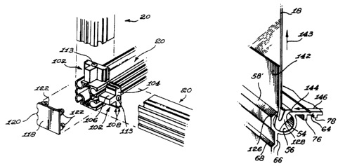
The panel locking component 124 defines a first :locking tongue 126 and a
second locking
1o tongue 128. The first locking tongue 126 and the second locking tongue 128
define a
locking channel 138 therebetween. The first locking tongue 126 defines a first
locking
tongue first end 130 and a first locking tongue second end 132. Similarly, the
second
locking tongue 128 defines a second locking tongue first end 134 and a second
locking
tongue second end 136. The first and second locking tongues 126, 128 are
pivotally
attached together by an hinge means preferably about their respective first
ends 130, 134.
The hinge means allows the first and second locking tongues 126, 128 to pivot
relative to
each other between an unlocking configuration shown in Figure 10 wherein they
are
relatively proximal relationship relative to each other and a locking
configuration
illustrated in Figures 11 and 12 wherein they are in a substantially spaced
relationship
2o relative to each other.
The first locking tongue 126, the second locking tongue 128 and the connecting
recesses
50, 52 are configured and sized so that in the unlocking configuration the
first and second
21
CA 02286745 1999-10-18
locking tongues 126, 128 can be easily at least partially inserted into and
retracted from
the connecting recesses 50, 52 without restriction from a retaining force
therebetween.
Also, the first locking tongue 126, the second locking tongue 128 and the
connecting
recesses 50, 52 are configured and sized so that in the locking configuration
the first and
second locking tongues 126, 128 fractionally abut against the retaining edges
54 thus
creating a retaining force therebetween. The second locking tongue 128
preferably
defines a locking groove 140 formed on its outer surface preferably adjacent
the second
locking tongue second end 136. The locking groove 140 is configured and sized
for
substantially fittingly receiving a retaining edge 54 therein when the panel
locking
1o component 124 is suitably positioned within a connected recess 50, 52 and
the locking
tongues 126, 128 are in the locking configuration.
In such a configuration, not only is a first retaining edge 54 securely
received within the
locking groove 140 but the opposing retaining edge 54 fractionally engages the
outer
surface of the locking tongue 126, even slightly deforming the latter inwardly
as shown in
Figure 11, thus ensuring both the maintenance of the tension in the window
panel 18 and
the creation of a substantially leak-proof seal. Furthermore, the apex of the
panel locking
component 124 abuttingly and fractionally contact the inner surface of the
inner segment
56 part of the connecting recess 50 further stabilizing the connection between
the panel
2o locking component 124 and the connecting recess 50. The apex of the panel
locking
component 124 is preferably configured so as to substantially conform to the
abutment
section part of the inner segment 56. Typically, in order to still further
increase the
22
CA 02286745 1999-10-18
locking action of the panel locking component 124, the second locking tongue
128 is
relatively thicker then the first locking tongue 126.
The panel locking component 124 preferably furl:her includes a biasing means
for biasing
the first locking tongue 126 and the second locking tongue 128 towards the
locking
configuration. In the preferred embodiment of the invention, the first locking
tongue
second end 132 merges integrally with the second locking tongue first end 134
at a
merging area made out of a resilient material and adapted to act both as the
hinge and
biasing means. Typically although by no means exclusively, the merging area is
made of
1o a suitable elastomeric or polymeric resin.
The locking component -to- window panel attachment means preferably includes a
substantially flat attachment segment 142 extending outwardly from the first
locking
tongue first end 130 preferably in a generally parallel relationship
therewith. The first
locking tongue 126 is preferably attached to the peripheral edge of the window
panel 18
by the attachment segment 142 using suitable fastening means such as high
frequency
thermo-welding means, an adhesive means or any other suitable means.
Each window panel 18 is made out of a suitable translucent or transparent
material. Each
2o window panel 18 is preferably made out of a relatively thin, lightweight
and flexible
panel of material such as a thin sheet of suitably treated polymeric resin.
Typically,
although by no means exclusively, the window panels 18 are formed of polyvinyl
chloride treated against premature ultra-violet aging. As mentioned
previously, the use of
23
CA 02286745 1999-10-18
relatively thin, lightweight and flexible sheets of material substantially
reduces the
overall weight of the solarium structure and substantially reduces the need
for costly
solarium supporting structures.
Each window panel 18 is configured and sized :.o as to be in a tense or taut
state when
mounted to its corresponding peripheral frame. In a preferred embodiment of
the
invention, each window panel 18 has an inherent self tightening characteristic
provided
by inherent resiliency, temperature related shrinkage properties or any other
suitable
means. In one particular embodiment of the invention, the window panels 18 are
made
out of a material that dilates under predetermined heat stresses so as to
facilitate mounting
thereof to the peripheral frame and then shrinks back to a predetermined size
at normal
operational temperatures so as to ensure tenseness. Tenseness of the window
panels 18
provides interesting visual and thermal properties. It also ensures a strong
connection and
a substantially tight seal between the window panels 18 and their respective
peripheral
frames.
When a window panel 18 is mounted to a corresponding peripheral frame member
20,
one of the retaining edges 54 is resiliently inserted within the locking
groove 140 while
the opposite retaining edge 54 abuttingly contacts the body of the first
locking tongue 126
2o preferably biasing the latter towards the second locking tongue as shown in
Figure 11.
In this locked configuration any pressure imparted upon the window panel 18 is
transmitted to the locking component in the form of a force schematically
illustrated by
24
CA 02286745 1999-10-18
the arrow 143 exerted in the direction of the geometrical plane formed by the
window
panel 18.
When the window panel 18 needs to be removed from its peripheral frame, the
intended
user merely needs to exert a pressure on a prol:ruding segment 144 part of the
second
locking tongue 128 in a direction indicated by arrow 146 in Figure 11. The
force exerted
on the protruding segment 144 allows the tongues 126, 128 to pivot about the
merging
area towards each other and thus allows resilient release of the retaining
recess 54 from
the locking groove 140.
The specific configuration of the locking tongues 126, 128 therefore not only
allows for
the easy installation and removal of window panels 18 from their corresponding
peripheral frames but also allows for a strong locking action which is further
increased by
internal or external pressures exerted on the window panels 18 by wind, or
other sources.
Furthermore, the combination of the resilient nature of the locking tongues
and of their
specific configuration which increases the frictional forces between the
mounting means
and the peripheral frame when the tongues are in their locked configuration
provides a
strong seal and thus a substantially leak proof connection which is even
further increased
2o in critical situations for example when high winds are combined with rain,
snow or the
like. The bond between the window mounting rr~eans and its associated
peripheral frame
is thus not only self solidifying, easy to remove but also substantially leak
proof.
CA 02286745 1999-10-18
As shown more specifically in figures l and 13 through 15, the specific cross-
sectional
configuration of the frame members 20 further allows for the latter to act as
structural
support for optional auxiliary panels such as a removable window screen 148, a
sliding
door 150 and the like.
The window screen 148 typically includes a meah 152 having a peripheral mesh
frame
154. The mesh frame 154 is mounted on a frame support 156 that includes a
peripheral
resilient pad 158. The frame support 156 also includes an integrally co-
extruded
elastomeric support leg 160 adapted to cooperate with a locking prong 162 for
supporting
1o therebetween a modified frame member 164 having a mounting channel 50. The
frame
support 156 further includes a resilient and substantially U-shaped clip 166
extending
integrally therefrom for attachment to a mounting; channel 50, 52.
The door 150 includes a set of supporting discs 168 rotatably attached by
corresponding
disc brackets 170. The supporting discs 168 are adapted to roll within guiding
tracks 172.
The door 150 may also include a door handle 174 and thermal strips 176 mounted
within
corresponding strip holders 178. Auxiliary guiding tracks 180 are preferably
provided
along with conventional door accessories.
The present invention relates not only to the structure of a novel solarium
and kit for
building the same but also to a novel method of constructing a solarium. This
method for
constructing a solarium includes the steps of initially erecting a frame
structure wherein
26
CA 02286745 1999-10-18
the frame structure includes a set of frame members together defining at least
one and
preferably a plurality of window openings. A panel locking component is
secured along
the marginal edge of a temperature shrinkable 'window panel. The next step
involves
heating the window panel so as to dilate the latter and then placing the
window panel in
one of the window opening with the panel locking component engaging the frame
members. The window panel is then allowed to cool and shrink until is becomes
tensed
by the peripheral pulling action of the peripheral :frame members to which it
is attached.
Numerous modifications, variations and adaptations may be made to the specific
1o embodiment hereinabove disclosed without departing from the scope of the
invention as
defined in the following claims.
27