Note: Descriptions are shown in the official language in which they were submitted.
CA 02286807 1999-10-19
WO 98/49446 PCT/US98/07148
_1_ _
BLOWER APPARATUS
Background and Summary of the Invention
The present invention relates to a blower apparatus. More particularly,
the present invention relates to an improved blower apparatus for controlling
fluid flow
to desired pieces of equipment, such as air mattress or other components of a
bed.
Although the illustrated embodiments of the present invention disclose
air blowers, it is understood that the present invention may also be useful
with other
types of fluid.
Blowers for supplying air to air mattresses or other pieces of equipment
are typically noisy due to operation of the blower motor and due to the intake
of air
into the blower. It is desirable to reduce the noise output from blowers which
are
often used next to a bed.
The present invention is designed to minimize noise output from a
blower apparatus. According to the present invention, a first blower assembly
is
provided for supplying air to a low air loss mattress. Such a blower assembly
typically
requires a relatively large blower motor. The present invention provides an
improved
mounting apparatus for locating the blower motor within a blower housing
without
providing a rigid connection between the blower motor and the blower housing.
This
reduces housing vibration and the associated noise of the blower motor.
A second blower apparatus is also provided. The second blower
apparatus is for controlling a second piece of equipment, such as an
articulating deck
assembly configured to be located below the air mattress. The second blower
assembly motor is typically smaller than the blower motor required to control
an air
mattress. The second motor is mounted to the second housing using vibration
mounts.
The second blower assembly includes an improved air intake manifold and intake
ring
designed to reduce noise associated with air entering the second blower motor.
Another feature of the present invention is a modular or stackable
arrangement for the first and second blowers. The first blower apparatus can
be
stacked on top of the second blower apparatus to form a single modular unit
for
controlling both the first and second pieces of equipment. The modular unit
can be
placed adjacent a bed to control both the air mattress and the articulating
deck or other
CA 02286807 1999-10-19
WO 98/49446 PCT/US98/07148
-2-
desired pieces of equipment. The first blower apparatus includes a retracting
mounting
bar which can be extended from the first blower housing to connect the modular
unit
to a foot board of a bed or other support if desired. The first and second
blower
apparatus can also be positioned on the floor adjacent the bed on their backs,
if
desired.
According to one aspect of the present invention, an apparatus is
provided for mounting a blower motor into a blower housing having an interior
region
for receiving the blower motor. The apparatus includes a top shell configured
to
surround a top portion of the blower motor, and a bottom shell configured to
surround
a bottom portion of the blower motor, the top and bottom shells being
configured to
hold the blower motor in the interior region of the housing without a rigid
connection
between the blower motor and the blower housing.
In the illustrated embodiment, the top and bottom shells are made from
a foam material such as a polystyrene foam. The top and bottom shells are
formed
from an air impermeable material.
Also in the illustrated embodiment, the top shell cooperates with the
bottom shell to define an air intake manifold to provide flow of intake air to
the blower
motor. The top shell includes a top end wall and the bottom shell includes a
bottom
end wall spaced apart from the top end wall to deflect intake air along a
predetermined
path in the intake manifold. In an alternative embodiment, the top and bottom
shells
cooperate to define an outlet manifold in communication with an outlet of the
blower
motor.
The illustrated blower motor has a top surface formed to include an air
inlet aperture. The top shell has an inner surface located above the top
surface of the
blower motor. The inner surface is formed to include a recessed portion
located over
the inlet aperture to permit intake air to enter the inlet aperture.
According to another aspect of the present invention, a blower
apparatus is provided for supplying fluid to a piece of equipment. The
apparatus
includes a housing for holding the blower motor. The housing includes a wall,
a fluid
inlet, and a fluid outlet. The apparatus also includes a mounting bar coupled
to the
wall of the housing. The mounting bar is movable relative to the housing from
a
retracted storage position to an extended position to couple the housing to a
support.
CA 02286807 1999-10-19
WO 98/49446 PCT/US98/07148
-3-
In the illustrated apparatus, the wall of the housing is formed to include
a recessed portion for receiving the mounting bar when the mounting bar is in
its
retracted position. The mounting bar is located in the recessed portion below
a surface
of the wall when the mounting bar is in its retracted position.
The illustrated mounting bar is coupled to the housing by a spring
mount assembly to bias the mounting bar to the retracted position. The
mounting bar
includes a U-shaped portion having first and second arms which extend into
first and
second elongated channels formed in the housing. The apparatus also includes
first
and second slide members coupled to the first and second arms, respectively.
The first
and second slide members are located in the first and second elongated
channels. First
and second fasteners are provided for securing the first and second arms to
the
housing. First and second springs are located on the first and second arms
between the
first and second slide members and the first and second fasteners,
respectively, to bias
the mounting bar to its retracted position.
According to yet another aspect of the present invention, a blower
assembly includes a first blower apparatus for supplying fluid to a first
piece of
equipment, and a second blower apparatus for supplying fluid to a second piece
of
equipment. The first blower apparatus includes a housing having a base, and
the
second blower apparatus includes a housing having a retention portion
configured to
couple the base of the first housing to the second housing.
The illustrated base includes a foot portion, and the second housing is
formed to include a recessed portion having a lip for engaging the foot
portion of the
base. The foot portion is formed along a front edge of the base, and the lip
is formed
along at least a front edge of the recessed portion of the second housing. A
fastener is
located along a rear wall of the first and second housings to secure the first
housing to
the second housing.
The illustrated assembly further includes an electrical connector for
electrically coupling the first housing to the second housing. The second
housing
includes a base for coupling the second housing to a third housing.
According to a fi~rther aspect of the present invention, an apparatus is
provided for reducing noise of intake air into an aperture formed in a wall of
a blower
motor. The apparatus includes a ring including an annular outer flange having
a
CA 02286807 1999-10-19
WO 98/49446 PCTIUS98/07148
_4_ _
dimension larger than the aperture in the wall of the blower motor, an annular
inner
portion configured to extend through the aperture, and a tapered surface
extending
between the outer flange and the inner portion to minimize noise caused by air
entering
the blower motor through the aperture.
A distal end of the inner portion illustratively has a dimension larger
than the aperture. The inner portion is flexible to permit the inner portion
to be
inserted into the aperture so that the inner portion retains the ring on the
wall of the
blower motor.
The illustrated apparatus further includes an intake manifold having a
front wall formed to include an outlet opening. The outer flange of the ring
is
configured to engage the front wall of the manifold to secure the manifold to
the
blower motor. The distal end of the inner portion of the ring passes through
the outlet
opening of the manifold and into the aperture of the blower motor so that the
inner
portion of the ring retains the ring and the intake manifold on the wall of
the blower
motor.
The illustrated intake manifold includes a baffle to direct air flow
through the intake manifold. The intake manifold includes a rear wall and a
side wall
extending between the front wall and rear wall. The side wall is formed to
include an
air inlet opening. Sound deadening foam located within an interior region of
the
manifold adjacent the front and rear walls.
According to a still further aspect of the present invention, a blower
apparatus includes a housing for holding a blower motor. The housing has an
air
outlet and a recessed grate formed to include a plurality of slots spaced
apart along an
axis to provide an air inlet. The apparatus also includes a filter located
over the
recessed grate, and cover coupled to the housing over the recessed grate and
filter.
The cover is formed to include a plurality of slots spaced apart along the
axis. The
slots of the cover being axially spaced apart from the slots in the recessed
grate.
Additional objects, features, and advantages of the invention will
become apparent to those skilled in the art upon consideration of the
following detailed
description of the preferred embodiment exemplifying the best mode of carrying
out
the invention as presently perceived.
CA 02286807 1999-10-19
WO 98/49446 PCT/US98/07148
-5-
Brief Description of the Drawings
The detailed description particularly refers to the accompanying figures
in which:
Fig. 1 is a diagrammatical view illustrating a modular blower assembly
including a first blower apparatus for controlling an air mattress and a
second blower
apparatus coupled to the first blower apparatus for controlling an
articulating deck,
with the modular blower assembly being coupled to a foot board of a bed;
Fig. 2 is a partial rear view of Fig. 1 further illustrating a mounting bar,
for coupling the blower assembly to the foot board of the bed;
Fig. 3 is a sectional view taken along lines 3-3 of Fig. 2, further
illustrating details of the extendable mounting bar assembly coupled to a
housing of the
first blower apparatus;
Fig. 4 is an exploded perspective view illustrating further details of the
mounting bar assembly and the first blower apparatus;
Fig. 5 is an exploded perspective view illustrating top and bottom shell
segments of a foam shell configured to surround a blower motor for mounting
the
blower motor within a housing of the first blower apparatus without rigidly
coupling
the blower motor to the blower housing;
Fig. 6 is an exploded perspective view illustrating further details of the
top and bottom foam shells, the blower motor, and sound foam located adjacent
the
top and bottom shells for mounting the blower motor in the first blower
housing;
Fig. 7 is a exploded perspective view of the first blower housing for
receiving the components illustrated in Fig. 6;
Fig. 8 is a sectional view taken through a portion of the first blower
housing further illustrating the configuration of the top and bottom shells
and
illustrating air flow through the shells, into the blower motor, and through
an outlet of
the blower housing;
Fig. 9 is a sectional view taken along lines 9-9 of Fig. 8 illustrating
further details of the top foam shell;
Fig. 10 is an exploded perspective view of the second blower apparatus;
.- CA 02286807 1999-10-19
. 7175-29685
~ ei;,."r:~i
~P~~ Z '~ ~ ~. rt ~' 1999
-6-
Fig. 11 is a partial sectional view illustrating an air intake ring and
manifold assembly coupled to an inlet of a blower motor of the second blower
apparatus to reduce air intake noise;
Fig. 12 is a sectional view taken along lines 12-12 of Fig. 11 illustrating
further details of the air intake manifold and intake ring;
Fig. 13 is an end elevation view, with portions broken away, illustrating
attachment of the first blower apparatus to the second blower apparatus to
form the
modular blower assembly of the present invention; and
..,t Fig. 14 is a partial side elevational view, with portions broken away,
illustrating the first blower apparatus installed on to and locked into
engagement with
"" the second blower apparatus.
Detailed Description of the Drawines
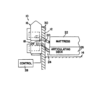
Referring now to the drawings, Fig. 1 illustrates a blower assembly 10
of the present invention mounted on a foot board 12 of a bed 14. The blower
assembly includes a first blower apparatus 16 and a second blower apparatus
18. As
discussed below, the first blower apparatus 16 and the second blower apparatus
18 are
modular units which can be stacked on top of each other to form the blower
assembly
i
10. The first blower apparatus 16 includes an outlet 20 for providing air flow
to an air
'20 mattress 22. Preferably, mattress 22 is a low air loss air mattress. One
suitable air
mattress is disclosed in U.S. Patent No. 5,794,288.
A second blower apparatus 18 has outlet lines 24 for controlling other
pieces of equipment, such as an articulating deck 26 located below the
mattress 22.
Illustratively, the articulating deck may include bellows for raising and
lowering
portions of the mattress. One such articulating deck is illustrated in U.S.
Application
Serial No. 08/841,125, entitled Mattress Articulation Structure by Soltani et
al., filed
April 29, 1997, the disclosure of which is hereby incorporated by reference.
A controller 28 is electrically coupled to the blower assembly 10.
Illustratively, controller 28 is a patient pendant to provide remote control
patient
inputs. An electrical connector 29 is provided for electrically coupling first
blower
apparatus 16 to second blower apparatus 18.
a'-'a~~~o- i i,... a,r ;. ~~ '"
CA 02286807 1999-10-19
WO 98/49446 PCT/US98/07148
-7-
The blower assembly 10 may be coupled to foot board 12 or other
support by an extendable and retractable mounting bar 30. The mounting bar 30
is
further illustrated in Figs. 2 and 4. As illustrated in Figs. 2 ans 4 the
mounting bar
includes a downwardly extending U-shaped portion 32 configured to be located
over a
top end 34 of foot board 12 to couple the blower assembly 10 to the foot board
12.
Additional details of the mounting bar assembly are illustrated in Figs. 3
and 4. First blower apparatus 16 includes a housing 36 having front and rear
housing
portions 38 and 40. Rear housing portion 40 is formed to include a recessed
area 42
for receiving the mounting bar 30 in its retracted position. As illustrated in
Fig. 3, the
mounting bar is located at or below a rear surface 44 of rear housing portion
40 when
the mounting bar 30 is in its retracted position.
The mounting bar 30 includes arms 46 coupled to U-shaped portion 32.
Opposite ends of arms 46 include threads 48. Each arm 46 extends through a
fastener
50, a spring 52, a sliding cylinder 54, and to an aperture 56 formed by open
tubes 58
formed in the rear housing portion 40. A suitable fastener 60, such as a nut,
holds the
sliding cylinder 54 and spring 52 on the arms 46. Plates 50 are secured to the
rear
housing portion 40 by fasteners 62. Spring 52 biases the mounting bar 30 to a
normally retracted position illustrated in solid lines in Fig. 3.
When it is desired to mount the blower apparatus 16 on to a bed 14, an
operator pulls the mounting bar 30 outwardly in the direction of arrow 64 of
Fig. 3 to
the extended position illustrated by dotted lines. Rear housing portion 40
includes an
expanded recessed section 66 to permit an operator to grab a portion of the
mounting
bar 30 and move the mounting bar 30 to its extended position. The operator can
then
hook the extended mounting bar 30 over a support.
As discussed above, the first blower apparatus 16 is used to supply air
or other fluid to a mattress 22 through supply tube 20. A problem associated
with
conventional blower assemblies is that the blower assemblies generate a large
amount
of noise due to operation of a blower motor in the intake of air through the
blower
. assembly.
The present invention provides an improved mounting assembly for
mounting a blower motor into a housing. Fig. 5 illustrates a motor mounting
assembly 70 including a top foam shell 72 and a bottom foam shell 74.
Illustratively,
CA 02286807 1999-10-19 ".. -
. 7175-29685
e1 e~. n ~ r-~
~~S 1 ~ .a.:: i~,1999
_g_
shells 72 and 74 are made from a polystyrene material. Bottom foam shell 74 is
formed to include a recessed portion 76 for receiving a blower motor 80 as
shown in
Fig. 6. Blower motor 80 includes a motor positioned within a housing having an
air
intake opening 82 formed in a top surface 84 and an air outlet 86. Top and
bottom
foam shells 72 and 74 are configured to receive and surround the blower motor
80.
The sound deadening foam material of shells 72 and 74 reduces noise of blower
motor
80. Bottom shell includes a curved outlet portion 88 and top shell 72 includes
a
curved section 90 for receiving outlet 86 of blower motor 80. Top foam shell
72
includes a rear wall 92, and bottom shell 74 includes a rear wall 94. Rear
wall 92 is
~J~
~.-.,, 10 spaced apart from rear wall 94 to define an air flow channel or
intake manifold through
'~~''' the foam mounting assembly as discussed in detail below.
Fig. 7 illustrates further details of the housing 36 of first blower
apparatus 16. Housing 36 includes an interior region 96 for receiving the foam
blower
mounting assembly 70 therein. After the foam blower mounting assembly 70
containing the blower 80 is inserted into the interior region 96 of housing
36, sound
foam components 98, 100, and 102 (Fig. 6) may be positioned around the foam
mounting assembly 70, if desired. Once the foam shell assembly 70 and blower
80 are
,.A,S positioned within the interior region 96 of housing 36, front and rear
housing portions
'"'~ 38 and 40 are coupled together with suitable fasteners 104 which extend
through
~,":' 20 apertures 106 and suitable fasteners 108 which extend through
apertures 110. The
mounting assembly 70 therefore eliminates the requirement for fastening the
blower
motor 80 directly to the blower housing 36. This reduces noise caused by
blower
vibration.
As discussed above, the foam shells 72 and 74 include spaced apart end
walls 92 and 94, respectively. These end walls 92 and 94 cooperate to define
an air
intake passageway or manifold including baffles for changing the direction of
inlet air
entering the housing 36 to decrease the noise caused by the intake air. After
the air
enters through cover 118, filter 116, and slots 114 of grate 112, air is
deflected
downwardly 90 ° by wall 92 of top shell 72. Intake air then deflects
upwardly 90 ° in
the direction of arrow 124 by end wall 94 of lower shell 74. Top shell 72 is
formed to
include a recessed portion 126 located above top surface 84 of blower motor 80
so
that air can enter recessed portion 126 in the direction of arrows 128 and
then enter air
~14~9~~~::~i3 ~H~i',
CA 02286807 1999-10-19
WO 98/49446 PCT/US98/07148
-9-
inlet 82 of blower motor 80 in the direction of arrows 130. Further details of
the
recessed portion 126 in communication with the air inlet 82 on top surface 84
of
blower motor 80 are illustrated in Fig. 9.
Air exiting outlet 86 of blower motor 80 is directed upwardly by a
baffle 132. Air is then directed downwardly and out through openings 138 and
140.
The foam shell assembly 70 therefore provides structure for mounting
of the blower motor 80 within housing 36, provides sound deadening features
around
the blower motor 80, and also provides an air intake manifold for deflecting
and
routing the intake air to reduce noise. The blower motor 80 is not rigidly
coupled to
the housing 36. This decreases noise due to vibration of the blower motor 80.
In
addition, since the molded foam shells 72 and 74 provide a passageway which
makes
the intake air change directions 90°, no additional baffling is
required to be formed
within the housing 36 to provide an intake manifold.
The outlet manifold illustrated by walls 132 and 139 can also be formed
as part of the foam shell housing assembly 70, if desired. Walls similar to
walls 92 and
94 are formed at the outlet end of shells 72 and 74 to provide an outlet
manifold.
Front and rear housing portions 3 8 are each formed to include a
recessed grate 112 having elongated slots 114. Once the housing is assembled,
a filter
116 is positioned over the recessed grate 112 and an outer cover 118 is
positioned
over the filter attached to housing 36. Cover 118 includes elongated slots 120
which
permit air flow into the housing 36 as discussed below. The slots 120 in the
outer
cover 118 are vertically offset along axis 121 from the slots 114 formed in
inner grate
112 as best illustrated in Fig. 8. The non-symmetrical, offset slots 120 and
114
provide noise reduction by changing the direction of intake air. The offset
slots 120
and 114 also permit the filter 116 to be flipped over and used again due to
the curved
air flow pattern between the offset slots 120 and 114 as illustrated by arrows
122 of
Fig. 8.
Details of the second blower apparatus 18 of the present invention are
illustrated in Fig. 10. The second blower apparatus 18 includes a blower
housing 1 SO
having a front housing portion 152 and a rear housing portion 154. Front and
rear
housing portions 152 and 154 define an interior region for holding the blower
motor
166 and control components of the blower apparatus 18.
CA 02286807 1999-10-19
WO 98/49446 PCT/US98/07I48
-10- -
Front and rear housing portions 152 and 154 are formed to include a
recessed grate 158 similar to the grate 112 discussed above with reference to
Fig. 7.
After the front and rear housing portions 152 and 154 are connected together,
a filter
160 is located over grate 158, and an outer cover 162 is coupled over to
housing 150
over the filter 160 as discussed above. A baffle 164 is spaced apart from
grate 158 to
direct intake air upwardly within the housing 150.
Blower motor 166 is mounted within an interior region 156. Blower
motor 166 is mounted to a rear surface 168 by a mounting plate 170, fasteners
172,
and vibration mounts 174. An elastomeric ring 176 is mounted around an outer
periphery of blower motor 166 to seal and reduce vibration transfer from the
motor
166 to the housing 150. An intake manifold assembly 178 is mounted to an inlet
end
180 of blower motor 166. Manifold assembly 178 includes a metal frame 180
having
an air inlet aperture 184 along one side of the frame 182, and a central air
outlet
aperture 186. An air guide track or baffle 188 is located within frame 182 to
deflect
1 S inlet air. A layer of sound deadening foam 190 is located within frame
182. A sound
reduction intake ring 192, discussed in detail below, is also located within
the manifold
assembly 178 for coupling the frame 182 to the wall 180 of blower motor 166.
Manifold assembly 178 further includes an outer metal plate 194 configured to
be
coupled to frame 182. A layer of sound deadening foam 194 is located on an
inside
surface of plate 194. Another layer of sound deadening foam 198 is located on
outside
surface of metal plate 194.
An outlet manifold and control housing 200 is mounted to a support
202 of rear housing portion 154 by suitable fasteners. A gasket 204 is located
between
support 202 and housing 200. Solenoid valves 206 and 208 provide control of
air flow
through to air outlets 210 and 212, respectively. Outlet connectors 214 and
216 are
coupled to rear housing portion 154 and to outlets 210 and 212, respectively.
Rear
housing portion 154 is coupled to front housing portion 152 by suitable
fasteners 218.
A latch 220 is also coupled to rear housing portion 154 by suitable fasteners
222.
The intake manifold assembly 178 is configured to be mounted to the
intake end 180 of blower motor 166 as best illustrated in Fig. 11. Intake ring
192
includes an annular outer flange 224 and an annular inner portion 226. The
outer
flange 224 is configured to abut a wall 228 of manifold frame 182. Flange 224
has an
CA 02286807 1999-10-19
WO 98/49446 PCT/US98/07148
-11-
outer diameter larger than a diameter of aperture 186 formed in frame 182.
Inner
portion 226 of intake ring 192 is configured to pass through aperture 186.
Portion
. 226 of ring 192 has a diameter slightly larger than a diameter of intake
aperture 230 of
blower motor 166. Therefore, intake ring 192 is snap-fit into the aperture 230
of
blower motor 166 to secure the intake manifold 178 and the ring 192 to blower
motor
166. In some instances, the ring 192 can be coupled directly to the blower
motor 166.
Intake ring 192 includes a tapered transition surface 232 between the
outer flange 224 and inner portion 226. This tapered or curved surface 232
provides a
smooth transition for intake air into the blower motor 166. By minimizing
rough
abrupt edges, the air intake noise is reduced by the ring 192.
In addition, air must pass through intake manifold 178 as best
illustrated in Fig. 12. Specifically, air enters aperture 184 in air intake
manifold 178 in
the direction of arrow 234. Intake air is then deflected upwardly through a
90° turn in
the direction of arrow 236 by baffle 238. Top wall 240 then deflects air
inwardly 90°
1 S in the direction of arrow 242. Such deflection of intake air by manifold
178 also
reduces air intake noise.
Figs. 13 and 14 further illustrate the modular, stacking feature of the
present invention. Housing 36 of first blower apparatus 16 is formed to
include a base
250. Base 250 includes an extended foot section 252 formed on front housing
portion
38. Rear housing 40 includes a recessed portion 254 having a hook 256 mounted
thereon.
Housing 150 of second blower apparatus 18 is formed to include a base
258 having a front foot portion 260 identical to base 250 of first blower
apparatus 16.
Housing 150 is also formed to include a top recessed portion 262 having an
outer lip
264.
When it is desired to stack the first blower apparatus 16 on the second
blower apparatus 18, the base 250 of first blower apparatus 16 is inserted
into the
recessed portion 262 of second blower apparatus 18. The foot portion 252 is
inserted
below the front lip 264 in the direction of arrow 266. First blower apparatus
16 is then
pivoted downwardly to the position illustrated in Fig. 14 with the base 250
nested
within the recessed portion 262 of housing 150. A hook portion 268 of latch
220
CA 02286807 1999-10-19
WO 98/49446 PCT/US98/07148
-12-
engages hook portion 256 on housing 36 to secure the first blower apparatus 16
to the
second blower apparatus 18,
Since the second blower apparatus 18 also includes a base portion 258,
the second blower apparatus 18 may be coupled to a recessed top of another
blower
apparatus (not shown) identical to the shape of the second blower apparatus
18. This
modular feature allows any desired number of blowers to be connected together
to
form a modular unit. Since the first blower apparatus 16 and second blower
apparatus
18 are coupled together, the entire blower assembly 10 can be mounted to a
foot board
12 of bed 14 or other supports, if desired. The blower assembly 10 can also be
located
adjacent bed 14 on its back.
Although the invention has been described in detail with reference to a
certain preferred embodiment, variations and modifications exist within the
scope and
spirit of the present invention as described and defined in the following
claims.