Note: Descriptions are shown in the official language in which they were submitted.
CA 02286818 1999-10-15
WO 98/46492 PCT/IB98/00561
1
IIvvIPROVED PLASTIC BOTTLE CLOSURE
FIELD OF THE INVENTION
The present invention relates to plastic bottle closures. The present
invention
has further relation to such closures with improved tear tabs.
BACKGROUND OF THE INVENTION
Tamper evident closures with tear handles are well known in the prior art.
Generally, prior embodiments of these closures have included a tear handle to
he
grasped by the consumer and pulled such that a frangible portion of the
closure wall
is broken allowing an annular portion of the closure wall to be removed, thus
permitting the consumer to remove the reclosable upper portion of the closure
from
the bottle. The removable portion of the closure wall is defined by an annular
line of
weakness and a vertical line of weakness to allow this portion to be easily
removed
from the remaining re-closable upper portion of the closure. Prior closures of
this
type may be seen in US. Pats. No. 4,066,182, 4,687,114, and 4,801,032. It is
common for the lower portion of the closure tear strip to come into contact
with a
downwardly sloped portion of the bottle neck finish, and for the lower portion
of the
tear strip and the corresponding portion of the bottle neck finish to be
forced
together at a relatively high pressure during the bottle capping process; this
may
result in rupture of the vertical line of weakness during capping. It is also
common
for these closures to be produced such that the fit between the lower portion
of the
closure and the bottle neck finish is loose enough to prevent the vertical
line of
weakness from being ruptured during capping. However, this loose fit also may
create a gap between the lower portion of the closure and the bottle neck
finish which
could facilitate tampering.
Closures have been detailed in the prior art which use other means to
eliminate this gap and improve tamper resistance as seen in U. S. Pats. No.
4,190,175,
5,027,969, and 5,307,948. These designs place a removable barrier on the
bottle
which prevents access to the lower region of the closure. This eliminates the
need for
a tight fit between the closure and the bottle. However, it is difficult to
reproduce
these features on a typical blow molded bottle with the accuracy and low cost
that
are possible on a standard injection molded or compression molded closure.
The present invention provides a novel tear handle which prevents damage to
the vertical line of weakness in the removable portion of the closure wall
when large
CA 02286818 1999-10-15
WO 98/46492 PCT/IB98/00561
2
forces are applied to the top surface of the closure during capping. The tear
handle
has a weak region which is designed to deform under pressure and shield the
vertical
line of weakness from high forces which can cause the vertical line of
weakness to
fracture. Shielding the vertical line of weakness from excessive capping
forces allows
the closure to be designed to fit the bottle more closely. This improved fit
between
the closure and bottle improves the tamper resistance of the closure as it is
installed
on the bottle.
There has therefore been a desire to have an improved bottle closure with an
improved tamper evident tear strip which does not fracture during the capping
operation, which provides for a better, tighter fit between bottle and
closure, and
which is easier for the consumer to tear from the container than tear strips
in the prior
art.
SUN1NIARY OF THE INVENTION
Disclosed is a plastic closure for a bottle, having a capping portion, and an
annular tear skirt attached to the capping portion by an annular line of
weakness
formed into the closure. The tear skirt has a lower peripheral edge, and a
starter line
of weakness formed into the tear skirt from the annular line of weakness to
the lower
peripheral edge. A tear tab is attached to the tear skirt proximate to the
starter line
of weakness, such that pulling on the tear tab will fracture the starter line
of
weakness. A relief recess is molded proximate to the point of attachment of
the tear
tab to the tear skirt and proximate to the lower peripheral edge, such that
the relief
recess acts to reduce the amount of tensile forces exerted on the lower
peripheral
edge, and therefore on the vertical line of weakness, when the closure is
applied to
the bottle.
The closure may be used with a container, the container being of a type that
has a neck area, a top opening, an annular top surface with a periphery and an
inner
edge, the inner edge defining the top opening, a top outer rim extending
downwardly
and outwardly from the periphery of the annular top surface, the top outer rim
defining a first plane, a lip formed at the lower edge of the top outer rim,
and a
bottom outer rim extending outwardly from the neck area. The closure may have
a capping portion which covers the opening. The capping portion may also have
an
inner surface and an outer surface, a first annular portion, the first annular
portion
defining a second plane, the first plane being substantially parallel to the
second
plane, the first annular portion further comprising a lip seal which comes
into contact
with the lip.
CA 02286818 1999-10-15
WO 98/46492 PCT/IB98/00561
3
A tear skirt extends downwardly from the capping portion. The tear skirt has
a bottom foot which comes into pressurized contact with the bottom outer rim
such
that a compressive force is exerted on the tear skirt, forcing the lip seal
into contact
with the lip. The tear skirt is attached to the capping portion by an annular
line of
weakness formed into the closure; it also has a lower peripheral edge. There
is a
vertical line of weakness formed into the tear skirt from the annular line of
weakness
to the lower peripheral edge.
A tear tab is attached to the tear skirt proximate to the vertical line of
weakness, such that pulling on the tear tab will fracture the vertical line of
weakness
starting at the Lower peripheral edge and continuously up to the annular line
of
weakness. A relief recess is molded proximate to the point of attachment of
the tear
tab to the tear skirt and proximate to the lower peripheral edge, such that
the relief
recess acts to reduce the amount of tensile forces exerted on the lower
peripheral
edge, and therefore on the vertical line of weakness, when the closure is
applied to
the bottle.
BRIEF DESCRTPTION OF THE DRAWINGS
While the specification concludes with claims particularly pointing out and
distinctly claiming the subject invention, it is believed the same will be
better
understood from the following description taken in conjunction with the
accompanying drawings in which:
Fig. 1. is a perspective view of one embodiment of a tamper evident closure,
as
applied to a bottle, that may be used with the present invention;
Fig. 2 is an elevational view of the closure of Fig. 1;
Fig. 3 is a sectional view through lines 3-3 of Fig. 2;
Fig. 4 is a perspective view of the underside of the closure of Fig. 1; and
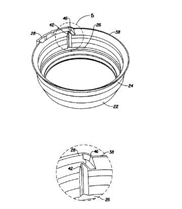
Fig. 5 is an exploded view of the point of attachment of the tear handle to
the tear
skirt, as it appears in Fig. 4.
DETAILED DESCRIPTION OF THE INVENTION
Referring now to the drawings in detail wherein like numerals indicate the
same element throughout the views, there is shown in Figures 1-3 an embodiment
of
a closure 10 of the present invention as applied to the top of a container.
This is just
one type of closure, among many, that may be employed with the present
invention.
Particularly referring to Figure 3, the container typically has a neck area 11
and an
opening. The opening is encompassed by an annular top surface 12, which in
turn
has an inner edge 14 and a periphery 16. A tap outer rim 18 angles downwardly
and
CA 02286818 1999-10-15
WO 98/46492 PCT/IB98/00561
4
outwardly from the periphery 16 of annular top surface 12. The lower edge of
the
top outer rim 18 overhangs a vertical portion of the neck area and forms lip
20. Lip
20 serves as a "seat" for a seal of the closure. Bottom outer rirn 32 extends
downwardly and outwardly from the lower end of the vertical portion of the
neck
area and serves as a "seat" for a portion of the closure.
Capping portion 22 of closure 10 is that portion which remains and may be
reused after tear skirt 24 is removed from the container. Lip seal 30 is part
of
capping portion 22; it mates with and engages lip 20. Tear skirt 24 extends
downwardly from capping portion 22. They connect at annular line of weakness
26
which is designed to fracture when a consumer pulls on tear tab 28. At the
lower end
of tear skirt 24 is a bottom foot 34 which is configured to engage with bottom
outer
rim 32. The area of closure 10 between lip seal 30 and bottom foot 34 is
dimensioned with respect to the area of the container between lip 20 and
bottom
outer rim 32 such that when closure 10 is secured onto the container, a
compressive
force is exerted on closure 10 between foot 34 and lip seal 30. This results
in an
enhanced seal between lip 20 and lip seal 30.
Referring to Figures 1, 2, 4, and S, a lower edge 38 may extend downwardly
and outwardly from bottom foot 34. This lower edge 38 is forced against bottle
surface 40 (see Fig. 3) during the capping operation. As lower edge 38 is
forced
downwards, it is forced outwards as well, as it slides down surface 40. This
downward and outward motion during capping causes a significant amount of
tensile
force to be exerted generally within tear skirt 24, but specifically about
lower edge
38. In prior art closures, this tensile force would accumulate at vertical
line of
weakness 42, shown in Figs. 4 and 5, specifically at the point on line of
weakness 42
proximate to lower edge 38. This causes fracture of line of weakness 42 in a
portion
of containers during the capping operation, and as a result, wasted product.
This
problem is due to the significant thickness of material in prior art closures
that is
molded at the point tear tab 28 connects to tear skirt 24, an area of
increased
strength. This area of increased strength funnels tensile forces during the
capping
operation toward the weakest link -- i.e., vertical line of weakness 42 -- and
causes it
to fracture.
This problem has been solved by providing a relief recess 46 (see Figs. 4 and
5), molded into the closure at the point of contact between tear tab 28 and
tear skirt
24, proximate to lower edge 38. Recess 46 results in the removal of a portion
of the
tear tab thickness where it attaches to tear skirt 24 proximate to lower edge
38.
Recess 46 results in a decrease of material in this region, which tends to
absorb
tensile forces during the capping operation, thus relieving vertical Iine of
weakness 42
CA 02286818 1999-10-15
WO 98/46492 PCT/IB98/00561
from these forces and preventing fracture thereof. Applicants have proved with
testing that, using this development, extreme forces may be applied during the
capping operation with absolutely no damage to vertical line of weakness 42;
in fact,
the bottle tends to deform before any damage occurs to the novel closure. In
- addition, recess 46 makes tear skirt 24 easier for consumers to tear off
closure 10
when consumption of product from the container is desired, by allowing the
line of
weakness 42 to be made thinner because it is shielded from the tensile
stresses
mentioned above and will not fracture as easily.
While particular embodiments of the present invention have been illustrated
and described herein it will be obvious to those skilled in the art that
various changes
and modifications can be made without departing from the spirit and scope of
the
present invention and it is intended to cover in the appended claims all such
modifications that are within the scope of this invention.