Note: Descriptions are shown in the official language in which they were submitted.
CA 02286995 2003-05-05
MULTI--LEVEL LEACHING SYSTEM
BACKGROUND OF THE INVENTION
FIELD OF THE INVENTION
This invention relates to systems for leaching liquid waste, particularly
waste water.
More particularly this invention relates to a system of configuring
cylindrical conduit used in
leaching systems. Even more particularly the invention relates to the use of
multiple levels of
cylindrical conduit. The material within which the conduit is located may
either disperse
moisture away from the conduit through capillary action, wicking into the
surrounding
material or fluid may be extracted tcom contaminated fluid which is within or
a part of a
material surrounding the conduit, the extracted fluid being more free of the
contaminants
which may be in the contaminated t"Iuid. A perforated cylindrical conduit is
one method
permitting wicking. The surrounding material provides capillary action to
transmit moisture
away from the cylinder and prevents the effluent from traveling directly from
the pipers of the
upper level to the conduits of the lower levels. Examples of these materials
include sand,
gravel, plastic fibers, wood producla, slag, and ash. A fabric or other
material may surround
the cylindrical conduit. The cylindrical conduit may be either smooth walled
or corrugated.
For septic systems, this includes any graveless systems such as the SB2TM,
ENVIRO-
SEPTICTM and GEO-FLOWTM systems. Other applications of this invention include
treatment
of oil-contaminated water and chemically contaminated water, in addition to
septic tank
effluent.
The multi-level configuration of the present invention creates a larger
leaching surface
in a fixed surface area than a single level leaching system. This larrger
leaching surface area is
beneficial for increasing bacterial concentration and installation of systems
in small spaces.
DESCRIPTION OF THE PRIOR ART
Leaching systems typically utilize substantially two-dimensional stone beds or
chambers. The multiple layering of leach beds, chambers and conduits has not
been feasible
up to now. One problem is that liqcricl from one leach area would return to
the system through
a lower leach area.
CA 02286995 2000-O1-14
2
Another problem is the difficulty in constructing multiple layers using
traditional methods.
SUMMARY OF THE INVENTION
The invention most fundamentally is a leaching system substantially comprised
of
subsystems of liquid permeable conduit, serial or parallel interconnected for
the serial or parallel
flow of fluid being processed. Fluid flow is within subsystems and between
subsystems from
one level to another level. Le., the subsystems of which the system is
comprised are located at
different depths one above the other within a "leach bed" or within the volume
designed to
process the contaminated/leached fluid.
The present invention, is a leaching system having at least two (2) leaching
subsystems
wherein each of the at least two leaching subsystems is planarly located at a
different depth within
the leaching field having the leaching system installed therein. The leaching
subsystems are fluid
flow connected such that fluid being leached either flows; ( 1.) sequentially
or serially through
one of the subsystems and then sequentially or serially through another of the
subsystems and
subsequently through yet another subsystem until the last of the subsystems;
or (2.) the fluid
being leached is divided such that the divided portions flow in a parallel
paths or substantially
simultaneously through one of the subsystems and then subsequently through the
remaining
subsystems either simultaneously or sequentially and in either sequential flow
or parallel flow
within the components of the subsystems. Each of the leaching subsystems has
at least one
liquid permeable conduit with means for providing for fluid flow connection at
an input end and
an output end, fluid flow being into the input end and out through the output
end. The means for
providing for fluid flow connection provides interconnection of each of the
liquid permeable
conduits which are members of a subsystem, in either serial or parallel flow
configuration and for
connection of one of the subsystems to another of the subsystems at a
different depth.
The present invention, in its most simple embodiment, is a mufti-level
leaching system for
leaching liquid waste comprising a plurality of leaching subsystems each of
which is planarly
positioned at a different depth, the leaching subsystems being fluid flow
connected such that fluid
being leached is caused to flow into and through each of the leaching
subsystems. The invention,
the mufti-level leaching system, leaches waste liquid through at least one
liquid permeable
conduits, preferably cylindrical conduits, which conduits are members of the
subsystems which
subsystems are planarly arranged in multiple levels. The number of leaching
subsystems and the
number of conduits within each subsystem will depend upon the magnitude or the
volume of
CA 02286995 2000-O1-14
3
fluid which is to be processed by leaching.
The present invention is composed minimally of two leaching cylinders with
each cylinder
arranged in two substantially horizontal planes. The uppermost plane contains
the first leaching
cylinder, which is supplied waste liquid by a source pipe. The lowermost plane
contains the final
leaching cylinder, which is connected to the first leaching cylinder by a
pipe. The first and final
leaching cylinders may be horizontally arranged with respect to one another by
any angle.
More preferably, the system includes a plurality of leaching
conduits/cylinders with the
cylinders arranged in two or more substantially horizontal planes, in
reference to the axial
direction of the leaching cylinders or conduit, thereby forming leaching
subsystems. The plane
created by orthogonals through the axial center-lines of the leaching conduit
need not be
substantially horizontal, i.e., the plane formed by the leaching subsystems is
substantially
horizontal in the direction of the axial center-lines but may be other than
horizontal in the direction
of the orthogonals to the center-lines. The uppermost leaching
subsystem,preferably planarly
configured, contains the first leaching cylinder, which is supplied waste by a
source pipe, and
may contain one or more intermediate cylinders. The lowermost leaching
subsystem, again
preferably planarly configured, contains the final leaching cylinder, which is
connected to the
preceding intermediate leaching cylinder, and may also contain one or more
intermediate
cylinders. The region between the uppermost and lowermost leaching subsystems
may contain
one or more intermediate cylinders, which are each connected to the preceding
leaching cylinder,
respectively.
Even more preferably, a liquid dispersing material surrounds the leaching
cylinders of the
system. The liquid dispersing material may be one or more of the following,
including but not
limited to, sand, gravel, plastic fibers, wood products, slag, and ash. The
material surrounds the
cylinders a given distance. The distance for a 12-inch cylinder is about 6
inches. Other distances
are acceptable when capillary action disperses the liquid away from the
leaching cylinder and not
back into the system.
One advantage of the present invention is the mufti-level system is greater
leaching volume
in a fixed surface area than a single level system. The additional leaching
levels of system allow
more leaching surface area to be utilized than a single level system.
Another advantage of the present invention is the present invention may be
used to treat a
variety of liquid waste including, but not limited to, septic tank effluent,
strong waste water
having high BOD and suspended solids concentrations, oil contaminated water,
and chemically
CA 02286995 2003-05-05
4
contaminated water. The contaminatc;d fluid rnay pass through the liquid
permeable conduit
from within to without the conduit or it may be drawn from outside the conduit
to within the
conduit as a processed fluid more fi~ee of the contaminants.
Yet, another advantage of the present invention is that any type of
cylindrical conduit
may be used with the rnulti-level l~:ac,l~ing system. For septic purposes,
this includes any
graveless system such as the SB2Tr', ENVIRO-SEPT1CTM, and GEO-FLOWTM brands of
leaching conduit.
Still yet, another advantage ol'the present invention is high bacterial
concentration.
This concentration of bacteria in a small surface area permits installation of
multi-level
leaching systems in small spaces.
These and further objects of the present invention will become apparent to
those
skilled in the art after a study of the present disclosure of the invention.
Therefore, in accordance with the present invention, there is provided a multi-
level
leaching system comprising:
a leaching field;
at least two leaching subsystems wherein each of said at least two leaching
subsystems is located at a different depth within said leaching field having
said leaching
system installed therein, each said leaching subsystem comprising:
at least one liquid permeable conduit each having an input end and an output
end,
means for providing fluid flow coy nection such that fluid being leached flows
into and
through said at least one liquid permeable conduit of one of said at least two
leaching
subsystems and subsequently into and through said at least one liquid
permeable conduit of
alt others of said at least two leaching subsystems.
Also in accordance with the present invention, there is provided a mufti-level
leaching
system comprising:
a leaching field;
two leaching subsystems wherein one of said leaching subsystems is at a lesser
depth
than the other of said two leaching subsystems within said leaching field
having said leaching
system installed therein, each said two leaching subsystems comprising:
a plurality of liquid permeable cylindrical conduit each having an input end
and an
output end, each said liquid permeable cylindrical conduit further comprises a
fabric of a
CA 02286995 2003-05-05
4a
selectable denier, said fabric being wrapped about a selected number of said
liquid permeable
cylindrical conduits, wherein said fabric further comprises treatment with
material selected
from the group consisting of, chemicals, bacteria, microbes such as known oil
digesting
microbes, said pretreatment to particularize the use of the multi-level
leaching system for
further processing and treating of said fluid being leached,
means for providing fluid flow connection such that fluid being leached flows
into
and through each said liquid permeable conduit of said one leaching subsystem
and
subsequently into and through each said liquid permeable conduit of said other
leaching
subsystem.
Further in accordance with the present invention, there is provided a mufti-
level
leaching system for dispersing liquid waste from a liquid waste source pipe,
said mufti-level
leaching system comprising:
a first leaching cylinder, having an axially directed center-line
therethrough, said first
leaching cylinder having first and second opposed end walls connected by a
liquid permeable
lateral wall, said first and second end walls of said first leaching cylinder
having an inlet
adapter and an outlet adapter, respectively, said inlet adapter attached
adjacent to said liquid
waste source pipe, said first: leaching cylinder substantially horizontally
oriented defining
thereby a substantially horizontal uppermost plane;
a final leaching cylinder, having an axially directed center-line
therethrough, said final
leaching cylinder having first and second opposed end walls connected by a
liquid permeable
lateral wall, said first and second end walls having an inlet adapter and an
end cap,
respectively, said final leaching cylinder substantially horizontally oriented
and configured
below said uppermost plane defining a substantially horizontal lowermost
plane, said final
leaching cylinder center-line forming an uppermost to lowermost cylinder angle
S2 with said
first leaching cylinder center-line o f between 0° and 90°;
a means for connecting saic:l outlet adapter of said first leaching cylinder
to said inlet
adapter of said final leaching cylinder, said connecting means having first
and second
openings, said first opening adjacently connected to said outlet adapter of
said first leaching
cylinder and said second opening adjacently connected to said inlet adapter of
said final
leaching cylinder; and
CA 02286995 2003-05-05
4b
means for dispersing liquid away from said first leaching cylinder and said
final
leaching cylinder, said dispersing means located adjacently to said cylinders.
Still further in accordance with the present invention, there is provided a
mufti-level
leaching system for dispersing liquid waste from a liquid waste source pipe,
said mufti-level
leaching system comprising:
a first leaching cylinder, said first leaching cylinder having first and
second opposed
end walls connected by a liquid permeable lateral wall, said first and second
end walls of said
first leaching cylinder having an inlet adapter and an outlet adapter,
respectively, said inlet
adapter attached adjacent to a liquid waste source pipe, said first leaching
cylinder
horizontally oriented at a first given angle with respect to the liquid waste
source pipe and
defining a substantially horizontal uppermost plane;
a final leaching cylinder, said final leaching cylinder having first and
second opposed
end walls connected by a liquid pe~7neable lateral wall, said first and second
end walls having
an inlet adapter and an end cap, respectively, said final leaching cylinder
horizontally oriented
at a second given angle with respect to the liquid waste source pipe and
configured bf;low
said uppermost plane defining a substantially horizontal lowermost plane;
at least one intermediate lea:~ching cylinders, each said at least one
intermediate
leaching cylinder having first and second opposed end walls connected by a
liquid permeable
lateral wall, said first and second end walls having an inlet adapter and an
outlet adapter,
respectively, each said at least one intermediate leaching cylinder
independently oriented with
respect to said liquid waste source pipe and configured vertically within the
inclusive range of
said uppermost plane to said lowermost plane, respectively, said at least one
intermediate
leaching cylinders having a first inlet adapter and a final outlet adapter,
said first inlet adapter
of said at least one intermediate leaching cylinders adjacently connected to
said outlet adapter
of said first leaching cylinder, said final outlet adapter of said at least
one intermediate
leaching cylinders adjacently connected to said inlet adapter of said final
leaching cylinder,
said at least one intermediate leaching cylinders having a first outlet
adapter and a final inlet
adapter, said at least one intermediate leaching cylinders sequentially
connected adjacently
together from said first outlet adapter to said final inlet adapter with said
outlet adapter of the
preceding cylinder adjacently connected to said inlet adapter of the following
cylinder;
CA 02286995 2003-05-05
4c
means for connecting each said at least one intermediate leaching cylinders
sequentially together, each said means for connecting having first and second
openings, said
first opening adjacently connected to said outlet adapter of the preceding
cylinder and said
second opening adjacently connected to said inlet adapter o f the following
cylinder oi° said at
least one intermediate leaching cylinders, respectively;
means for connecting said cutlet adapter of' said first leaching cylinder to
said first
inlet adapter of said at least one intermediate leaching cylinders, said means
for connecting
having first and second openings, said first opening adjacently connected to
said outlca
adapter of said first leaching cylinder and said second opening adjacently
connected to said
first inlet adapter of said at least one intermediate leaching cylinders;
means for connecting said final outlet adapter of said at least one
intermediate
leaching cylinders to said inlet adapter of said final leaching cylinder, said
connecting means
having first and second openings, said first opening adjacently connected to
said final outlet
adapter of said at least one intermediate leaching cylinders, said second
opening adjacently
connected to said inlet adapter of said final leaching cylinder; and
means for dispersing liquid away from said first leaching cylinder, said at
least one
intermediate leaching cylinders, and ;>aid final leaching cylinders, said
dispersing means
located adjacently to said cylinders.
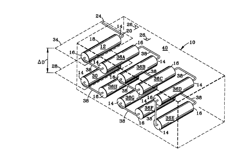
BRIEF DESCRIPTION OF THE DRAWINGS
FIG. 1 is a schematic representation of a right side top perspective view of
the serially
configured multi-level leaching system;
FIG. 2 is a schematic representation of a perspective view taken from the top
rear left
side of the serially configured multi-level leaching system of Fig. 1;
FIG. 3 is a schematic representation of a right side top perspective view of a
most
fundamental serially configvned mufti-level leaching system with two leaching
cylinder one
cylinder substantially orthogonal t<r tloe second and one of the cylinders
being at a depth
different than the second;
FIG. 4 is a schematic representation of a perspective view taken from the top
rear left
side of the mufti-level leaching system of Fig. 3;
CA 02286995 2003-05-05
4d
FIG. 5 is a schematic repre:~entation of a top, right rear perspective view of
the serially
configured multi-level leaching system within a leach field showing the
difference in depth
OD between one subsystem and another subsystem; and
FIG. 6 is a schematic repre~>entation of a side plan view of the serially
configured
multi-level leaching system within a leach field showing the difference in
depth DD between
one subsystem and another subsystem and the angle of the planes of the
subsystems to the
horizontal.
DESCRIPTION OF THE (REFERRED EMBODIMENTS
The system 10 seen in FIG;i. l-4 has a first leaching cylinder 12. The first
leaching
CA 02286995 2000-O1-14
cylinder 12 is composed of first and second end walls 14, 16 connected by a
liquid permeable
lateral wall 18. The first and second end walls 14, 16 contain inlet and
outlet adapters 20, 22,
respectively. Inlet adapter 20 is configured to receive liquid waste from a
liquid waste source
pipe 24. First leaching cylinder 12 is positioned in a relatively horizontal
position with respect to
the lateral wall 18, and at a horizontal angle with respect to the liquid
waste source pipe 24. First
leaching cylinder 12 defines a horizontal uppermost plane 28 of system 10.
Final leaching
cylinder 12 has a center-line forming an uppermost to lowermost cylinder angle
S2 of between 0°
and 90° with the first leaching cylinder center-line. Similarly, where
cylinders 12 and
intermediate cylinder 38 of the uppermost subsystem 10A (see FIGS. 5 and 6)
form an
uppermost plane 1 1A, the orientation of cylinders 30 and intermediate
cylinders 38 forming the
lowermost plane, the cylinder center-lines may form any angle S2 which is
appropriate for the
terrain and the leaching requirements. It should be clearly noted that while
the drawing figures
depict cylinders having center-lines which are substantially parallel each to
the other in one
subsystem 10A and those in the other susbsystem 10B, such is not required.
There may be
engineering reasons for non-parallel orientations between the cylinders of the
same subsystem.
The invention of system 10 is substantially comprised of subsystems of liquid
permeable conduit,
serial or parallel interconnected for the serial or parallel flow of fluid
being processed from one
level to another level, i.e., which subsystems are located at different depths
one above the other
within leach bed 8.
System 10 further has a final leaching cylinder 30. The final leaching
cylinder is
composed of first end wall 14 and an end cap 32 connected by a liquid
permeable lateral wall 18.
The final leaching cylinder is positioned in a relatively horizontal position
with respect to the
lateral wall 18, and at a horizontal angle b with respect to the liquid the
first leaching cylinder 12.
The final leaching cylinder 30 defines a horizontal lowermost plane 28 of the
system 10. The
lowermost plane 28 is a first given distance above the water table or
restrictive layer, and is a
second given distance below the uppermost plane 34. The first end wall 14
contains an inlet
adapter 20. Inlet adapter 20 is configured to receive liquid waste from the
outlet adapter 22 of the
preceding leaching cylinder 36 or the preceding first leaching cylinder 12.
The system 10 may further contain intermediate leaching cylinders 36. The
intermediate
leaching cylinders 36 are each composed of first and second end walls 14, 16
connected by liquid
permeable lateral wall 18. The first and second end walls 14, 16 contain inlet
and outlet adapters
20, 22, respectively. The inlet adapter 20 is configured to receive liquid
waste from the outlet
CA 02286995 2000-O1-14
6
adapter 22 of the preceding leaching cylinder 36 or the preceding first
leaching cylinder 12. The
outlet adapter 22 is configured to transmit liquid waste to the inlet adapter
20 of the subsequent
intermediate leaching cylinder 36 or the subsequent final leaching cylinder
30.
The configuration of the system 10 includes a means for connection 38 to
transmit liquid
waste from the inlet adapter 20 of the preceding leaching cylinder 12, 36 to
the outlet adapter 22
of the subsequent leaching cylinder 30, 36. The connection means 38 may be a
solid pipe. The
solid pipe may be composed of a plastic material, such as PVC, a metal,
another suitable material
or a combination of substances.
The configuration of the system 10 includes a means for dispersing liquid 40.
The
dispersing means 40 includes, but is not limited to, one or more of the
following materials: sand,
gravel, plastic fibers, wood products, slag and ash. The dispersing means 40
is placed adjacent
the leaching cylinders 12, 30, 36 to a given distance. The given distance can
be about 6 inches to
facilitate capillary action away from the cylinder 12, 30, 36 but not into
another cylinder 12, 30,
36.
In the present embodiment, leaching cylinders 36 A-H are shown in FIGS. 1 and
2 and
may be collectively referred to as intermediate leaching conduit or cylinders
36. Waste liquid
introduced into system 10 flows through the liquid waste source pipe 24 and
into the first
leaching cylinder 12 through the inlet adapter 20 located in the first end
wall 14 of the cylinder
12. A portion of the waste liquid is contained within the first leaching
cylinder 12 and begins to
permeate through the liquid permeable lateral wall 18 of the first leaching
cylinder 12. The
remainder of the waste liquid flows out of the outlet adapter 22 of the second
end wall 16 of the
first leaching cylinder 12.
The waste liquid continues to flow from the outlet adapter 22 of first
leaching cylinder 12
through the pipe connecting means 38 into the inlet adapter 20 of the
intermediate leaching
cylinder 36A. A portion of the waste liquid is contained within the
intermediate leaching cylinder
36A and begins to permeate through the liquid permeable lateral wall 18 of the
intermediate
leaching cylinder 36A. The remainder of the waste liquid flows out of the
outlet adapter 22 of the
second end wall 16 of the intermediate leaching cylinder 36A.
The waste liquid continues to flow out from the outlet adapter 22 of the
intermediate
leaching cylinder 36A through the pipe connecting means 38 into the inlet
adapter 20 of the
intermediate leaching cylinder 36B. A portion of the waste liquid is contained
within the
intermediate leaching cylinder 36B and begins to permeate through the liquid
permeable lateral
CA 02286995 2000-O1-14
7
wall 18 of the intermediate leaching cylinder 36B. The remainder of the waste
liquid flows out of
the outlet adapter 22 of the second end wall 16 of the intermediate leaching
cylinder 36B.
The waste liquid continues to flow out from the outlet adapter 22 of the
intermediate
leaching cylinder 36B through the pipe connecting means 38 into the inlet
adapter 20 of the
intermediate leaching cylinder 36C. A portion of the waste liquid is contained
within the
intermediate leaching cylinder 36C and begins to permeate through the liquid
permeable lateral
wall 18 of the intermediate leaching cylinder 36C. The remainder of the waste
liquid flows out of
the outlet adapter 22 of the second end wall 16 of the intermediate leaching
cylinder 36C.
The waste liquid continues to flow out from the outlet adapter 22 of the
intermediate
leaching cylinder 36C through the pipe connecting means 38 into the inlet
adapter 20 of the
intermediate leaching cylinder 36D. A portion of the waste liquid is contained
within the
intermediate leaching cylinder 36D and begins to permeate through the liquid
permeable lateral
wall 18 of the intermediate leaching cylinder 36D. The remainder of the waste
liquid flows out of
the outlet adapter 22 of the second end wall 16 of the intermediate leaching
cylinder 36D.
The waste liquid continues to flow out from the outlet adapter 22 of the
intermediate
leaching cylinder 36D through the pipe connecting means 38 into the inlet
adapter 20 of the
intermediate leaching cylinder 36E. A portion of the waste liquid is contained
within the
intermediate leaching cylinder 36E and begins to permeate through the liquid
permeable lateral
wall 18 of the intermediate leaching cylinder 36E. The remainder of the waste
liquid flows out of
the outlet adapter 22 of the second end wall 16 of the intermediate leaching
cylinder 36E.
The waste liquid continues to flow out from the outlet adapter 22 of the
intermediate
leaching cylinder 36E through the pipe connecting means 38 into the inlet
adapter 20 of the
intermediate leaching cylinder 36F. A portion of the waste liquid is contained
within the
intermediate leaching cylinder 36E and begins to permeate through the liquid
permeable lateral
wall 18 of the intermediate leaching cylinder 36F. The remainder of the waste
liquid flows out of
the outlet adapter 22 of the second end wall 16 of the intermediate leaching
cylinder 36F.
The waste liquid continues to flow out from the outlet adapter 22 of the
intermediate
leaching cylinder 36F through the pipe connecting means 38 into the inlet
adapter 20 of the
intermediate leaching cylinder 36G. A portion of the waste liquid is contained
within the
intermediate leaching cylinder 36 G and begins to permeate through the liquid
permeable lateral
wall 18 of the intermediate leaching cylinder 36G. The remainder of the waste
liquid flows out of
the outlet adapter 22 of the second end wall 16 of the intermediate leaching
cylinder 36G.
CA 02286995 2000-O1-14
8
The waste liquid continues to flow out from the outlet adapter 22 of the
intermediate
leaching cylinder 36G through the pipe connecting means 38 into the inlet
adapter 20 of the
intermediate leaching cylinder 36H. A portion of the waste liquid is contained
within the
intermediate leaching cylinder 36G and begins to permeate through the liquid
permeable lateral
wall 18 of the intermediate leaching cylinder 36H. The remainder of the waste
liquid flows out of
the outlet adapter 22 of the second end wall 16 of the intermediate leaching
cylinder 36H.
The waste liquid continues to flow out from the outlet adapter 22 of the
intermediate
leaching cylinder 36H through the pipe connecting means 38 into the inlet
adapter 20 of the final
leaching cylinder 30. The waste liquid is contained within the final leaching
cylinder 30 by the
end cap 32 of the second end wall 16 of the final leaching cylinder 30 and the
waste liquid
permeates through the liquid permeable lateral wall 18 of the final leaching
cylinder 30.
The component cylinders 12, 30, 36 of system 10 are arranged such that the
first cylinder
12 is within the uppermost horizontal plane 28 and the final leaching cylinder
30 is within the
lowermost horizontal plane 34. The lowermost plane 34 must be a given distance
below the
uppermost plane 28 to permit a minimum amount of dispersing material 40 to be
placed between
the planes 28, 34. The uppermost and lowermost horizontal planes 28, 34 may
contain one or
more intermediate leaching cylinders 36, respectively. The region between the
uppermost and
lowermost horizontal planes 28, 34 may contain one or more intermediate
leaching cylinders 36.
Alternatively, the region between the two cylinders may contain no
intermediate leaching
cylinders 36.
The arrangement of the component cylinders in the preferred embodiment is such
that the
first leaching cylinder 12 is oriented toward the waste liquid source pipe 26.
Subsequent
intermediate cylinders in the uppermost horizontal plane 28 are oriented in
parallel, alternating
directions to facilitate serial connectivity with short pipes 38. The
lowermost horizontal plane 34
is similar to the arrangement of the uppermost horizontal plane 28 with a
vertical pipe 38
connecting the intermediate cylinders 36 together. The cylinders 12, 30, 36 do
not have to be
oriented in parallel, alternating directions to one another. Cylinders 12, 30,
36 may be
configured such that a triangular, rectangular, square or any shape is formed.
Cylinders 12, 30,
36 may also be configured perpendicular to one another in descending levels in
a grid-like
fashion.
FIG. 5 is a schematic representation of a top, right rear perspective view of
the serially
configured multi-level leaching system 10 within a leach field 8 showing the
difference in depth
CA 02286995 2000-O1-14
9
OD between one subsystem 10A and another subsystem IOB.
FIG. 6 is a schematic representation of a side plan view of the serially
configured multi-
level leaching system 10 within a leach field 8 showing the difference in
depth OD between one
subsystem 10A and another subsystem lOB and the angle 13 of the planes 11A and
11B of the
subsystems 10A and lOB respectively to the horizontal.
While not illustrated in a drawing figure, to provide for further processing
of the fluid,
(either processing of a contaminated fluid from outside the conduit by drawing
fluid into the
inside of the conduit which fluid now inside the conduit is more free of
contaminant or providing
for the transmission of fluid from within the conduit and into the material
within which the multi-
level system is installed) a single layer or a multilayer fabric of varying
deniers, may be wrapped
around the outer surface of the liquid permeable wall of at least some of
cylinders, first or input
conduit 12, last or final conduit 30, or any of the intermediate conduits 36
for the processing and
treatment of fluids which must be treated to remove materials so that the
resultant treated fluid
may be reused and/or returned to the earth and particularly to the water
table. Each layer, where
there are multiple layers, may be of selected denier, and in combination with
conduit around
which it is wrapped, either smooth-walled or corrugated, when placed in a
drainage field 8 or
used with leaching system 10 provides a large surface area whereon consequent
biodegradation
of said oils, greases and chemicals takes place permitting treated fluid to
pass omnidirectionally
through the assemblage of fibers and subsequently leach into the ground.
Additionally, the
fabric layers may be pretreated with chemicals, bacteria, and/or microbes such
as known oil
digesting microbes in order to particularize the use of leaching system 10 in
the processing or
treating of fluids.
Other embodiments of system 10 may also contain one or more distribution boxes
that
permit more than one serial path. The distribution box may be located at one
or more of the
following places including the liquid waste source pipe 24, the first leaching
cylinder 12, any of
the intermediate leaching cylinders 36, before the final leaching cylinder 30,
and the connecting
pipe 38.
It is clear that the present invention, a mufti-level leaching system having a
plurality of
preferably planar subsystems each subsystem at different depths within a
leaching field for the
processing and treatment of fluids and many of its attendant advantages is
understood from the
foregoing description and it will be apparent that various changes may be made
in the form,
construction and arrangement of the parts thereof without departing from the
spirit and scope of
CA 02286995 2000-O1-14
1~
the invention or sacrificing all of its material advantages, the form
hereinbefore described being
merely a preferred or exemplary embodiment thereof.