Note: Descriptions are shown in the official language in which they were submitted.
CA 02287184 1999-10-21
WO 98/49456 PCT/US98/08496
-1-
CONTROLLABLE OVERRUNNING COUPLING
Technical Field
The invention relates to torque-transmitting
couplings for accommodating torque transfer from a driving
member to a driven member, but which will permit freewheeling
overrunning motion of the dri~ring and driven members upon a
torque reversal.
HackQrc~und Art
Overrunning coupling assemblies are used for
transferring torque from a driving member to a driven member
in a variety of structural environments. This permits the
transfer of torque from a driving member to a driven member
while permitting freewheeling motion of the driving member
relative to the driven member when torque is interrupted.
U.S. Patent No. 5,597,057 issued January 28, 1997,
describes an overrunning coupling assembly including a pair of
planar coupling plates situated in close juxtaposed
relationship, each coupling F>late being rotatable about a
common axis. Each planar coup=Ling plate includes a plurality
of recesses formed therein. Torque-transmitting struts are
received within the recesses of one coupling plate while a
spring positioned beneath each strut urges the strut to pivot
about a pivot axis, whereby each strut projects from the recess
in the one coupling plate into engagement with recesses formed
in the other coupling plate.
When torque is transferred from one coupling plate
to the other coupling plate in one direction, at least one
strut becomes locked in the respective recesses of the coupling
plates. If the driven coupling plate overruns the driving
a 30 coupling plate when torque transfer is interrupted, the struts
will ratchet over the recesses of the driven plate, each strut
pivoting about its respective pivot axis while still being
urged by its respective spring into ratcheting engagement with
the driven coupling plate. This ratcheting engagement of the
CA 02287184 1999-10-21
WO 98!49456 PCT/US98l08496
-2-
struts and the driven coupling in the overrunning condition
generates unwanted noise while further causing undesirable
wearing of both the struts and the driven coupling plate.
Disclosure Of The Invention
It is an object of the invention to provide an
improved planar overrunning coupling assembly wherein the
overrunning condition is characterized by an absence of
ratcheting engagement of any strut with a coupling plate.
A further object of the invention is to provide an
improved planar overrunning coupling assembly for selectively
transferring torque in a first direction only, in a second
direction only, or in neither direction.
The improved planar coupling assembly of this
invention includes a pair of planar coupling plates situated
in close juxtaposed relationship, each coupling plate being
rotatable about a common axis. A plurality of torque-
transmitting struts are received within recesses formed in one
coupling plate. Each strut is urged by a spring to pivot about
a pivot axis and thereby project from the recess in the one
coupling plate into engagement with recesses formed in the
other coupling plate..
The coupling assembly of the invention also includes
a strut retainer plate disposed between the coupling plates and
generally rotatable with one of the coupling plates. The strut
retainer plate includes a plurality of angularly-spaced
apertures. The retainer plate is angularly movable relative
to the one coupling member from a first angular position,
wherein at least one given strut extends through an aperture
into engagement with the other coupling plate, to a second
angular position, wherein the at least one given strut does not
extend through an aperture in the retainer plate or, at a
minimum, does not pivot in a manner sufficient to extend
through the aperture and engage with the other coupling plate.
With the struts thus prevented from engaging the
driven coupling plate, ratcheting in the overrunning condition
is eliminated, and any noise that would be associated with
CA 02287184 1999-10-21
WO 98/49456 PCT/US98/08496
ratcheting of the struts over the recesses of the driven plate
is likewise eliminated. Moreover, the possibility of wear of
the struts and coupling plates is substantially reduced. As
such, our improved coupling assembly is particularly adapted
for high-speed operating conditions and for operation under
low-volume lubricating oil operating conditions. Still
further, manufacture of our improved coupling assembly does not
require the precision machining operations that are required
in the manufacture of conventional sprag couplings and roller
couplings, wherein the presence of burrs or other manufacturing
defects would otherwise greai:ly increase component wear.
Indeed, in accordance with another feature of the invention,
many of the components may be manufactured using powder metal
casting and forming techniques.
According to another feature of the invention, a
coupling assembly has three operating states, each of which is
characterized by a separate angular position of the strut
retainer plate relative to the one coupling plate with which
it generally rotates. When the: strut retainer plate is in a
first angular position relative to the one coupling plate,
struts disposed in each of a first series of recesses in the
one coupling plate are allowed t.o pivot and extend through the
apertures in the strut retainer plate into engagement with a
first series of complementary recesses in the other coupling
plate. In the meantime, struts disposed in a second series of
recesses in the one coupling plate -- each of which pivot in
an angular direction opposite to the angular direction of the
pivotal motion of the struts in t:he first series of recesses --
are prevented by the retainer plate from engaging with a second
series of complementary recesses in the other coupling plate.
This permits torque transfer from the driving member to the
driven member only in a first rotational direction.
When the strut retainer plate is in a second angular
position relative to the one coupling plate, the struts
disposed in the second series of recesses are allowed to pivot
and extend through the retainer plate apertures into engagement
with the second series of complementary recesses in the other
CA 02287184 1999-10-21
WO 98/49456 PCT/US98/08496
-4-
coupling plate. In the meantime, struts disposed in the first
series of recesses are prevented by the retainer plate from
engaging with a first series of complementary recesses in the
other coupling plate. This permits torque transfer from the
driving member to the driven member only in a second driving
direction opposite the first driving direction.
When the strut retainer plate assumes a third angular
position relative to the one coupling plate with which it
generally rotates, the struts in each series of recesses in the
one coupling member are held within their respective recesses,
thereby permitting free-wheeling motion of the coupling plates
in both directions.
Brief Description Of The Drawinas
FIGURE 1 is a perspective view of an overrunning
coupling assembly wherein torque is transferred from a driving
shaft to a driven coupling plate and which will permit free
wheeling motion in a clockwise direction;
FIGURE 2 is a view similar to Figure 1 indicating the
operating mode in which free-wheeling motion is permitted in
each direction;
FIGURE 3 is a view similar to Figures 1 and 2
indicating that torque may be transferred from a driving shaft
to a driven coupling plate while permitting free-wheeling
motion in a counterclockwise direction;
FIGURE 4 is a partial exploded assembly view of the
planar coupling illustrated in Figures 1, 2 and 3;
FIGURE 5a is a plan view of a driven clutch plate for
the coupling assembly of Figures 1, 2 and 3;
FIGURE 5b is an end elevation view of the coupling
plate of Figure 5a;
FIGURE 6a is a plan view of a strut retainer plate,
which is located between the planar coupling driving plate and
the planar coupling driven plate as indicated in Figure 4;
FIGURE 6b is an end elevation view of the retainer
plate of Figure 6a;
CA 02287184 1999-10-21
WO 98/49456 PCT/US98/08496
-5-
FIGURE 7 is a detailed perspective view of the strut
springs that are located in recesses formed in the planar
coupling driving plate;
FIGURE 8a is a plan view of the planar coupling
driving plate which shows the' recesses for retaining the
springs of Figure 7;
FIGURE 8b is an end elevation view of the coupling
plate of Figure 8a;
FIGURE 9a is a plan view of a strut that is adapted
to be located in the recesses of: the plate shown in Figure 8a;
FIGURE 9b is an end elevation view of the strut of
Figure 9a;
FIGURE 10 is a plan view of a snap-ring that is used
in the planar coupling assembly to retain the driving coupling
plate in assembled relationship with respect to the driven
coupling plate;
FIGURE lla is a view of the driving shaft with
external splines that engage internal splines on the driving
coupling plate;
FIGURE llb is a side elevation view of the driving
shaft of Figure lla;
FIGURE 12a is a part~~al assembly view showing the
strut retainer plate, the struts, and the driving coupling
plate in assembled relationship wherein the strut retainer
plate is positioned angularly to permit torque delivery in one
direction;
FIGURE 12b is a view similar to Figure 12a wherein
the strut retainer plate is positioned to permit transfer of
torque in the opposite direction;
FIGURE 12c is a view similar to Figures 12a and 12b
wherein the retainer plate is positioned to permit free-
wheeling motion in each directic>n;
FIGURE 13a is cross-;sectional view of the planar
coupling assembly wherein the strut retainer plate is
positioned for torque transfer in a first direction;
CA 02287184 1999-10-21
WO 98!49456 PCT/US98/08496
-6-
FIGURE 13b is a view similar to Figure 13a showing
the strut retainer plate shifted angularly to a position that
permits torque delivery in a second direction;
FIGURE 13c is a view similar to Figures 13a and 13b
wherein the strut retainer plate is moved to a position that
will accommodate free-wheeling relative motion of the coupling
plates in either rotary direction;
FIGURE 14 is a plan view partly in section of the
coupling assembly of the invention wherein a central actuator
shaft is situated within the coupling plates;
FIGURE 15a is a view of a modified planar coupling
assembly that is adapted for torque transfer in one direction,
but which permits free-wheeling relative motion of the coupling
plates in the opposite direction, the strut retainer plate
being positioned to permit free-wheeling motion; and
FIGURE 15b is a view similar to Figure 15a wherein
the strut retainer plate is positioned for permitting torque
transfer from one coupling plate to the other.
Best Modes For Carrying Out The Invention
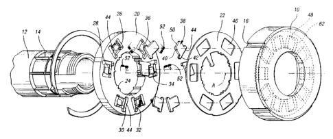
Figure 1 shows at 10 a driven plate of a planar
coupling assembly. Not shown in Figure 1 is a driving coupling
plate that is nested within the driven coupling plate. The
driving coupling plate is drivably connected to a torque input
shaft 12. This driving connection is established by internal
splines formed on the driving coupling plate, which drivably
engage external splines 14 on the shaft 12.
The driven coupling plate 10 may be provided with
drive keyways 16 which, in turn, establish a driving connection
with a driven coupling member, for example, in a power
transmission mechanism.
A strut retainer actuator shaft 18 is situated within
the torque input shaft 12. This actuator shaft is best seen
in Figure 14. It may be oscillated about its axis so that its
angular disposition relative to the shaft 12 can be changed.
Actuator shaft 18 is drivably connected to a strut retainer
plate, which will be described subsequently, thereby causing
CA 02287184 1999-10-21
WO 98/49456 PCT/US98/08496
_;_
the strut retainer plate to be adjusted angularly with respect
to the axis of the shaft 12.
Figure 2 corresponds to Figure 14. Figure 2
indicates, however, that the driven coupling plate 10 can free
s wheel in both angular directions. This is illustrated by the
bi-directional arrow shown in Figure 2. The bi-directional
free-wheeling motion is achieved in the operating mode
illustrated in Figure 2 as the actuator shaft 18 is adjusted
on its axis relative to the shaft 12 to a position intermediate
the position that effects torque' transfer in a first direction
and a position that effects torque transfer in the opposite
direction.
Figure 3 is a view similar to Figures 1 and 2, but
it illustrates a single directional arrow. This arrow
designates the free-wheeling motion in a direction opposite to
the direction of free-wheeling motion of Figure 1, although
torque transfer in the opposite direction is effected. The
operating mode shown in Figure :3 is achieved by adjusting the
actuator shaft 18 to a third operating position relative to the
shaft 12, thereby adjusting the strut retainer plate to a
torque transfer position opposite to the torque transfer
position for the operating mode illustrated in Figure 1.
In Figure 4, we have illustrated the clutch assembly
in an exploded view. The driving coupling plate, as shown at
20, is adapted to be received in the driven clutch plate 10.
Located intermediate the juxtaposed faces of the coupling plate
20 and the coupling plate 10 is a strut retainer plate 22.
The driving coupling plate is provided with splines
24, which engage drivably the external splines 14 on the shaft
12. The driving coupling plate 20 has a first pair of adjacent
recesses 26,28 situated at a first angular position; a second
pair of adjacent recesses 30,32 situated at a second angular
position displaced 120° from the first angular position; and
a third pair of recesses 34,36 at a third angular position
displaced 120° from the second angular position.
There are six struts 3B received in the six recesses
26,28,30,32,34,36 in driving coupling plate 20. Each strut 38
CA 02287184 2003-11-25
_g-
has a planar substantially rectangular portion 40 and a pair
of ears 42, the latter being located at one margin of the
strut. The edge of the strut on which the ears 42 are
formed defines a pivotal edge that registers with one edge
44 of its companion recess.
As seen in Figure 4, the pivotal edge of the strut
in recess 26 is located proximate to the pivotal edge 44 for
the adjacent strut in recess 28 at the first angular
position. Similarly, the pivotal edges for the struts
located at the second angular position are located in close
proximity, one with respect to the other. This is true also
of the struts for recesses 34 and 36 at the third angular
position.
The strut retainer plate 22 is provided six
apertures 46. These are arranged angularly about the axis
of the clutch, which is shown at A. The six apertures 46
are arranged in pairs, each pair being disposed 120' out of
position with respect to the other pairs of recesses.
V~lhen the retainer plate 22 is appropriately
positioned to a first angular position for torque transfer
in one direction, one aperture 46 will be disposed directly
over the recess 26, another will be disposed directly over
the recess 30, and another will be disposed directly over
recess 34. Thus, one recess will be disposed over one
recess of each pair of recesses in the plate 20.
Alternatively, when the retainer plate 22 is adjusted
angularly in the opposite direction to a second angular
position, an aperture 46 in the retainer plate 22 will be in
direct registry with each of recesses 28, 32 and 36.
The driven coupling plate 10 is provided with
angularly spaced recesses 48 in its internal planar face.
These recesses 48 are evenly-spaced about the axis A and are
arranged at a radial location corresponding to the radial
location of the recesses 26-36 in the driving coupling plate
20.
The apertures 46 and the recesses 48 are sized so
that the edges 50 of the struts 38 can enter the recesses 48
in the driven coupling plate 10 and engage one edge of the
recesses 48 to establish a locking action between the struts
CA 02287184 1999-10-21
WO 98/49456 PCT/US98/08496
_c~_
and the driven coupling plate 10 that will permit torque
transfer between the driving coupling plate 20 and the driven
coupling plate 10.
If retainer plate 22 is adjusted about axis A to its
first angular position such that: an aperture 46 fully registers
with recess 26, recess 28 will be out of registry with the
adjacent aperture 46 and will be at least partially covered by
the retainer plate 22. Thus, 'the strut located at recess 28
will be held in place in the recess 28 to prevent pivotal
motion about the pivotal edge 44. This prevents entry of the
strut into the recesses 48 of the clutch plate 10. Similarly,
with the retainer plate 22 in :its first angular position, an
aperture 46 will be fully regristered with recess 30 while
recess 32 will be at least partially covered by the plate 22,
and an aperture 46 will be fu:Lly registered with recess 34
while recess 36 will be at least partially covered by the
retainer plate 22. This permits torque transfer from the
driving coupling plate 20 to the driven coupling plate 10 in
a first direction.
If the plate 22 is adjusted about the axis A to its
second angular position so that the apertures 46 register with
recesses 28, 32 and 36, the struts in those recesses may pass
through apertures 46 and engage the opposite edge of the
recesses 48 in the driven coupling plate 10. At the same time,
recesses 26, 30 and 34 will be at least partially covered by
the retainer plate 22 to prevent the struts located in those
recesses from pivoting into engagement with recesses 48 in the
driven coupling plate 10. This. permits torque transfer from
the driving coupling plate 20 to the driven coupling plate 10
in a second direction opposite i~he first direction.
If the retainer plate 22 is adjusted to a third
angular position intermediate the two torque transfer
positions, both struts 38 in the. first pair of recesses 26,28
will be at least partially covered by retainer plate 22 and,
thus, prevented from moving pivotally about their respective
pivotal edges into engagement with the driven coupling plate
10. Similarly, the struts 38 respectively located in second
CA 02287184 2002-06-28
-10-
and third pairs of recesses 30,32,34,36 will be prevented from pivotal
movement into
engagement with the driven coupling plate 10. When the retainer plate 22 is
thus positioned
in its third angular position, the driving coupling plate 20 and the driven
coupling plate 10
can free-wheel, one with respect to the other, in either direction.
As seen in Figure Sa, the driven coupling plate 10 has its recesses 48
equally spaced about the axis A of coupling. They are strategically positioned
so that three
of them will permit engagement of one of each of the three pairs of struts
carried by the
driving plate 2U. During torque transfer in the opposite direction, the
strategic position of
the recesses 48 will permit engagement of the other strut of each of the three
pairs of struts
in the coupling plate 20.
Although any suitable strut spring can be used with the invention, Figure
7 shows in perspective a strut spring 52 used in this embodiment of the
invention. One
spring 52 is located under each strut. '1'he springs 52 are located in the
recesses formed in
the plate 20. Spring reaction arms 54 on the spring 52 engage the base of the
driving plate
recesses. An intermediate actuator portion 56 engages the planar portion 40 of
each strut.
Figure 8a shows a plan view of the driving coupling plate 20. Seen in
Ffigure 8a are recesses 26 through 36. Each recess has a pocket of generally
horseshoe
shape with sides that receive the arms 54 of the springs 52. The horseshoe
shape pocket
is illustrated in Figure 8a at 58. Figure 8a also shows an elongated portion
60 of the
recesses that receive the struts. The recesses 60 are sized so that the ear
portion 42 at the
pivotal edge of each strut can be secured in place.
The edge of each recess 48 in driven coupling plate 10 that is engaged by
an edge 50 of a strut 38 when the retainer plate 22 is in its first or second
angular position
is illustrated in Figure 4 by reference numeral 62.
5 As seen in Figures I la and l lb, the end of the shaft 12 is provided wide
an axially
extending slot 64, which extends to a circumferentiat groove 66 formed in the
portion of the
CA 02287184 2003-11-25
-11-
shaft that is splined, as shown at 14. The inside diameter
of the groove 66 generally is equal to the minor diameter of
the splines 14. When the driving coupling plate 20 is
received within the driven coupling plate 10, the plates are
held axially fast on the shaft 12 by retainer ring or snap-
ring 68. The snap-ring 68 is received in internal groove 69
formed in the driven coupling plate 10, as best seen in
Figure 5a.
When the coupling is assembled, the retainer plate
22 is located within the groove 66. As seen in Figure 6b,
retainer plate 22 is provided with internal splines 70, the
minor diameter of the splines 70 being piloted on the base
of the groove 66. The retainer plate 22 thus can move
angularly about the axis A of the clutch. The retainer
plate 22, as seen in Figure 6a, is provided with an actuator
tab 72, which is received in slot 64 in the shaft 12 when
the coupling is assembled. This is best seen in Figure 14.
The actuator shaft 18 also is provided with a slot 74, as
seen in Figure 14. The inner extremity of the actuator tab
72 is received in this slot 74 in shaft 18.
The width of the slot 74 is substantially less
than the width of the slot 64. Thus, when the actuator
shaft 18 is indexed rotatably relative to the shaft 12, the
retainer plate will be adjusted angularly about the axis of
the coupling relative to the recesses in the driving
coupling plate 20. When the actuator shaft 18 is moved in
one direction, the retainer plate will be adjusted to a
position that will retain one strut of each of the pairs of
struts 26 or 28, 30 or 32, and 34 or 36, while permitting
the other strut of each pair to pass through the apertures
46 into engagement with the recesses of the driven clutch
plate 20. When the shaft 18 is rotatably indexed in the
opposite direction, the other struts of each of the pairs of
struts will be held in their respective recesses in the
driving plate 20, while permitting the companion strut of
each pair to enter the recesses of the driven coupling
plate.
Figures 12a, 12b and 12c show the three operating
positions of the retainer plate 22. When the retainer plate
CA 02287184 1999-10-21
WO 98/49456 PCT/US98/08496
-12-
22 is positioned in its first angular position as shown in
Figure 12a, the strut at location A is in full registry with
the aperture 46, whereas the strut at location B is out of
registry with its aperture 46. Similarly, the struts at the
companion locations C and D and the struts at the companion
locations E and F have one strut out of registry and the other
strut in full registry with the apertures 46.
When the plate 22 is adjusted to its second angular
position as shown in Figure 12b, the one strut at locations A,
C and E becomes misaligned with its respective aperture 46,
while the other struts at companion locations B, D and F fully
register with their respective retainer plate apertures 46.
This permits torque transfer in a direction opposite to the
direction of torque transfer associated with Figure 12a.
Figure 12c shows the third angular position of the
retainer plate that will permit tree-wheeling motion in both
directions. In this instance, the plate 22 is adjusted
angularly relative to the shaft 12 so that both struts of each
pair of struts are out of registry with respect to their
apertures 46.
Figure 13a is a cross-sectional view that further
illustrates the relationship of the struts with respect to the
coupling plates 10 and 20 when the coupling is conditioned for
torque transfer in the operating mode shown in Figure 12a. The
location of the springs 52 also is best seen in Figures 13a,
13b and 13c.
Figure 13b shows the position of the retainer plate
22 relative to the coupling plates 10 and 20 when torque is
delivered in a direction opposite to the direction for the
operating mode of Figure 13a. Figure 13c shows a position of
the retainer plate 22 relative to the coupling plates 10 and
20 when the assembly is conditioned for the operating mode in
which free-wheeling motion can occur in each direction.
We have shown in Figures 15a and 15b an embodiment
of the invention wherein torque can be transferred in one
direction but not in the opposite direction. Free-wheeling
motion in the opposite direction, however, is accommodated.
CA 02287184 2002-06-28
-13-
In Figure 15a, the retainer plate 22' is adjusted to a position relative to
the plate 20'
so that the apertures 46' are out of registry with respect to the recesses in
the
coupling plates. The retainer plate 22' then will prevent pivotal motion of
the struts
38' about their respective pivotal edges 44. The coupling in the operating
mode
shown in Figure 15a will permit free-wheeling motion. When the assembly
assumes
the position shown in Figure 15b, the retainer plate 22' is indexed so that
the
apertures 46' fully register with the recesses in the coupling plates. T his
permits the
struts 38' to engage the recesses in the driven coupling piate.
The elements of the embodiment of Figures 15a and 15b that have a
lU counterpart in the embodiment of Figures 1-14 carry prime notations on
corresponding reference numerals.
The plate 20' in the embodiment shown in Figures 15a and 15h
carries a locator pin 76 which is received in a slot 78 in the retainer plate
22'. This
pin and slot arrangement limits the angular displacement of the retainer plate
22' so
1 s that it will assume either one position C.~r the other. In Figure 15b, the
pin register
with one end of the slot to permit full registry of the apertures 46 with
respect to the
recesses in the coupling plates.
When torque transfer through the coupling structure terminates and
the coupling assembly assumes the overrunning mode shaven in Figure 15a, the
20 retainer plate 22' will be dragged by the fluid dynamic drag forces in the
lubricating
oil so that it is indexed to the position shown in Figure 15a during the
overrunning
operating mode. Upon a torque reversal, the drag farces on the retainer plate
22 '
are reversed, thereby allowing the apertures 46' to register with the recesses
and the
coupling plates and establish a one-way torque transfer path.