Note: Descriptions are shown in the official language in which they were submitted.
CA 02287215 1999-10-22
-1-
Title= ERGONOMIC HANDLE
Field of the Invention
The present invention relates to handles and in particular relates to
ergonomic handles.
Background of the Invention
Currently paint brush handles which are commercially available, generally
speaking
have straight handles which are attached to a brush head including casing and
bristles. The
straight handle can either be gripped as shown schematically in Figure 2 when
the brush is
used for trimming and/or cutting into corners,or the brush can also be clasped
or held as
shown schematically in Figure 5 near the distal end of the handle when a
longer reach is
required and/or when large surface areas are painted which do not require
exact delineation
of the brush bristles.
A sash or angled bristle brush is generally used for trimming or cutting
painting in
order to provide a uniform edge which can follow into corners and/or around
windows and/or
trim of houses. When painters are trimming and/or gripping the brush as
schematically
shown in Figure 2, it is important that a very steady hand hold the brush in
order that a
straight line or edge can be painted. In current paint brush handle designs,
the web of the
hand (being the portion between the thumb and the fore finger) is impinged
upon by the
straight handle and therefore, the hand must bend to fit around the straight
handle in a very
CA 02287215 1999-10-22
-2-
unnatural position. This can cause cramping of the hand resulting in tremors
and shaking
leading to poor painting quality and straightness of lines.
In order to reduce hand fatigue, a number of paint brush designs have been
developed
as follows.
US Design 292,348 titled Paint Brush by Roberts et al, filed July 9, 1986
depicts an
ergonomic paint brush handle.
US Design 311,455 titled Paint Brush by John Rodpass, filed December 16, 1987
also
depicts an ergonomic paint brush handle.
US Design 255,845 titled Pistol Grip Brush by Wood, filed August 31, 1978
depicts
a paint brush handle having a pistol style grip end.
US Design 251,160 titled Paint Brush Handle or the Like by Kelly III et al,
filed
November 8, 1977 depicts a further ergonomic paint brush handle.
US Patent 4,495,669 by Hooper titled Dual-Grip Handle Brush for Painting and
the
Like, filed January 6, 1983 describes a paint brush having a dual handle to be
held in either
CA 02287215 1999-10-22
-3-
conventional manner or with a pistol grip attachment.
The handles disclosed in the above-mentioned patents are directed at designing
a
handle which is be held in a manner totally different than conventional paint
brush handles.
The present design incorporates a ergonomic handle design which enhances the
present
method of holding a paint brush by ensuring that hand fatigue is minimized
while using a
modified paint brush handle. The present design allows the paint brush to be
held in the
conventional manner as well as in a preferred manner and retains the handle
centrally aligned
along the paint brush. This ensures that the weight balance of the handle
together with the
brush is still in the proper proportion. Therefore, the current design
optimizes the traditional
holding position of the hand rather than provide for an entirely different way
of holding a
brush.
Summarv of the invention
The present invention an ergonomic paint brush handle comprises
a) a head section having a shoulder end, a brush end, a brush edge and a
shoulder
surface, said brush end of said head section for receiving a brush head, and
said head
section being oriented substantially along a brush plane;
CA 02287215 1999-10-22
-4-
b) a longitudinal handle section oriented substantially along a handle axis,
said handle
axis and said brush plane are substantially parallel to each other and
disposed at an
offset distance;
c) a transition means for rigidly connecting said shoulder end of said head
section to
one end of said handle section; and
d) wherein said ergonomic handle for gripping by placing a fore finger along
said
brush edge, and a thumb on said shoulder surface and said handle section lying
in the
web of a hand between the fore finger and the thumb, such that when said
handle is
gripped in a hand said transition section provides relief for the web of a
hand.
Preferably said transition means comprises a transition section rigidly
attached at one end to
said shoulder end of said head section, and at the other end to one end of
said handle section,
said transition section being oriented longitudinally along a transition axis
which is disposed
at an angle theta relative to said brush plane; such that when said handle is
gripped in a hand
said transition section provides relief for the web of a hand.
Preferably said transition section is dimensioned such that the off set
distance falls within the
range '/2 a forefinger thickness to 3 times a forefinger thickness.
CA 02287215 1999-10-22
-5-
Preferably said angle theta falls within the range 30 degrees to 60 degrees.
Preferably the angle theta and the transition section length are selected such
that there is just
enough relief for the web of the hand such that the fore finger phalanges and
meta carpal
bones can align and lie substantially along the brush plane.
Preferably said transition section and said handle section project centrally
from said head
section such that said ergonomic handle is symmetrial about a handle plane.
Preferably said handle section is rod shaped and lying substantially
longitudinally along said
handle axis.
Preferably said ergonomic handle is oriented for gripping by a right hand.
Preferably said ergonomic handle is oriented for gripping by a left hand.
Preferably said head section is planar proximate said brush end and tapers
toward said
shoulder end.
Preferably said transition section is dimensioned to confonn to the shoulder
end dimensions
CA 02287215 1999-10-22
-6-
at one end and the handle section dimensions at the other end thereby
providing a smooth
transition beteen the head section and the handle section.
Brief description of the drawings
The invention will now be described by way of example only, with references to
the following drawings in which:
FIG. 1 is a the top plan view of the current invention, an ergonomic handle,
shown
together with a brush head and a hand gripping the handle.
FIG. 2 is a side elevational view of the present invention, an ergonomic
handle,
shown together with a brush head and a hand clasping the handle.
FIG. 3 is a side elevational view of the present invention, an ergonomic
handle,
shown together with a brush head and a flat surface which it is lying on.
FIG. 4 the top perspective view of the present invention, an ergonomic handle,
shown together with a brush head and a flat surface which it is lying on.
FIG. 5 is a perspective view showing the ergonomic handle in use together with
a
brush head and a hand clasping the end of the ergonomic handle showing
schematically how the handle is used in working overhead into the corners of
walls.
FIG. 6 is a top perspective view of the present invention an ergonomic handle
together with a brush head
FIG. 7 is a inverted perspective view of the present invention an ergonomic
handle
together with a brush head.
FIG. 8 is a top plan view of the present invention an ergonomic handle
together with
CA 02287215 1999-10-22
-7-
a brush head.
FIG. 9 is a side plan view of the present invention an ergonomic handle
together with
a brush head.
FIG. 10 is a top plan view of the present invention an ergonomic handle
together with
a brush head.
FIG. 11 is a side plan view of the present invention an ergonomic handle
together
with a brush head.
FIG. 12 is a top plan view of the present invention an ergonomic handle
together
with a brush head.
FIG. 13 is a side plan view of the present invention an ergonomic handle
together
with a brush head.
FIG. 14 is a side elevational view of the present invention an ergonomic
handle
together with a brush head.
FIG. 15 is a side elevational view of the present invention an ergonomic
handle
together with a brush head.
FIG. 16 is a side elevational view of the present invention an ergonomic
handle
together with a brush head.
Detailed description of the preferred embodiment
Definitions:
Web: The portion of the hand located between the fore finger and the the thumb
which
normally impinges upon a paint brush handle when held as shown in Figure 2.
Brush head: The portion of a paint brush normally including bristles mounted
in a metal
casing. The bristles normally eminate from one end of the casing and the other
end of the
casing is normally mounted onto a paint brush handle.
CA 02287215 2006-09-28
-8-
Fore finger thickness: The thickness (roughly diameter) of a forefonger at its
largest point.
Normally this ranges between 1/2 inch and 1'/2 inches.
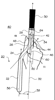
The present invention, an ergonomic handle, shown generally as 20 includes a
handle
section 22, a transition section 24, and a head section 26. Mounted on
ergonomic handle 20
is a brush head shown generally as 40 which includes a casing 28 having
bristles 30
projecting therefrom. Brush head 40 is of the type generally known in the art
where casing
28 is generally made of metal and or tin, and contains material within the
casing to securely
hold bristles 30 within the casing. The upper portion of casing 28, namely
upper casing 31,
is adapted to receive the brush end 27 of head section 26 of ergonomic handle
20, and is
usually fastened to head section 26 either by crimping, gluing, and/or
nailing. Head section
26 also has a shoulder end 29 which is connected to one end of transition
section 24. As
viewed in Figures 2 and 6 ergonomic handle 20 is preferably symettrical about
handle plane
71.
Referring now to Fig. 1, the present invention ergonomic handle 20 is shown
together
with a hand 60 holding and gripping ergonomic handle in the preferred manner
for use with
this invention. Fore finger 42 is placed along brush edge 64, and thumb 48 is
place upon
shoulder surface 66 as best shown in Fig. 1 and 2. By holding ergonomic handle
20 in this
manner, the web oil part of hand 60 lying between fore finger 42 and thumb 48,
is
accommodated and relieved by transition section 24 of ergonomic handle 20.
Bristles 30,
casing 28, and head section 26 as shown in Fig. 6 lie substantially along
brush plane 32.
Transition section 24 runs at an angle with respect to brush plane 32 as shown
by transition
axis 34. Handle section 22 runs longitudinally along handle axis 36, as shown
in Fig. 1.
Schematically shown in Fig. 1 are the bones within the hand 60, namely
phalanges 44,
CA 02287215 1999-10-22
-9-
part of fore finger 42, and metacarpals 46 which are found in the palm of hand
60. The
present invention, ergonomic handle 20, minimizes the distortion of the
phalanges 44 and
metacarpals 46 allowing them to lie substantially along a straight line namely
along
brush plane 32 as shown in Fig. 1. This is accomplished by providing for
relief for web 68
of hand 60 by the addition of transition section 24 to a traditional straight
handle.
As best seen in Fig. 1, the distance between brush plane 32 and handle axis 36
is
shown as offset distance 38. The offset distance will depend upon the angle of
transition
section 24, relative to the brush plane 32. In addition, the overall length of
transition section 24, namely transition lenght 53, will also contribute to
offset distance 38.
In other words, offset distance 38 can be increased by increasing the angle
between transition
axis 34 and brush plane 32, namely angle theta 51, or increasing transition
section length 53.
Fig. 8-16 show variations in lenght of the transition section 24 as well as
the angle
between transition axis 34 and brush plane 32. By way of example only and not
limiting the
angles that are possible, Fig. 9 depicts a 30 degree angle theta 51 between
the transition axis
34 and the brush plane 32, Fig. 11 depicts a 45 degree angle theta 5lbetween
the transition
axis 34 and the brush plane 32, and Fig. 13 depicts a 60 degree angle theta 51
between the
transition axis 34 and the brush plane 32.
In use, ergonomic handle 20 can alleviate hand strain by providing for
alignment of
the phalanges 44 and the metacarpals 46 along a straight brush plane 32 as
depicted in
Fig. 1. Commercially available brushes generally have straight handles which
impinge upon
web 68 of hand 60 of the user. As a result, the hand must curl around the
brush handle in
order to grip the head section 26 of a handle. This is an unnatural position
for the hand and
as a result fatigue quickly sets in to the person that is using a
convonational handle.
Therefore, the present design allows for a natural alignment of the bones,
mainly the
CA 02287215 1999-10-22
-10-
phalanges 44 and the metacarpals 46, thereby allowing the hand 60 to grip
ergonomic handle 20 in a natural position, thereby, minimizing fatigue of the
user.
Ergonomic handle 20 if preferrably gripped by placing fore finger 42 along
brush edge
64 and thumb 48 on shoulder surface, thereby providing relief for web 68 by
transition section 24 which projects away from web 68.
Preferably, the angle theta 51 between transition axis 34 and brush plane 32
is 45
degrees, however, as shown in Fig. 8-19, the angle theta 51 can vary between
30 degrees and
60 degrees and still be effective. Generally speaking, the smaller the angle
the larger the
transition section length 53 becomes. In other words, in order to obtain the
same relief for
web 68 of hand 60 with a smaller angle theta 51, the longer transition length
of 53 is
normally required.
Almost any angle theta 51 will work, however, practically speaking the range
of
values which seem to work best in practice are angle theta between 30 degrees
and
60 degrees.
Note that the ergonomic handle 20 design can be used with a sash brush shown
in
Fig. 8 or a straight brush that is shown in Fig. 10 and Fig. 2. It will be
apparent to those
skilled in the art that ergonomic handle 20 must be made in the left hand
version and a right
hand version when ergonomic handle is mated with a sash or angle type brush.
Casing 28 is just slightly larger than head section 26 and is adapted to just
fit snugly
over head section 26. The width of fore finger 42 is shown as thickness 90 in
Fig. 1 and in
practice it has been found that offset distance 3 8, in order to be effective
as an ergonomic
handle and to ensure the best alignment of the phalanges 44 and metacarpals 46
of hand 60,
CA 02287215 1999-10-22
-11-
the offset distance 38 preferably ranges between one half the thickness 90 to
three times the
thickness 90. In practice the angle theta is normally chosen to be 45 degrees
and the
transition section length 53 is then selected to vary offset distance between
one half the
thickness 90, to three times the thickness 90 of fore finger 42. Preferably,
offset distance 38
is two times the thickness 90 of fore finger 42.
In addition to allowing hand 60 to comfortable hold ergonomic handle 20 in a
manner
which prevents fatigue of hand 60, by offsetting handle axis 36 from brush
plane 32, one can
see in Figs. 3 and 4 by providing a pivot 52 ergonomic handle 20 when placed
on a flat
surface 50; bristles 30 of brush head 40 sit elevated above flat surface 50 at
a height 70 above
flat surface 50. A person skilled in the art, of course, will realize that the
weight of handle
section 22 and head section 26 must be enough to offset the weight of bristles
30 and casing
such that the ergonomic handle pivots preferably to the right of pivot 52 as
shown in Fig.
3. To ensure that ergonomic handle 20 pivots to the right as shown in Fig. 3
elevating
15 bristles 30 to a height 70 above flat surface 50, pivot 52 is placed at a
point such that the
balancing favours the lifting of bristles 30 above flat surface 50. In
addition, weights can be
placed within ergonomic handle to yield the correct balance. The advantage of
this is when
the ergonomic handle 20 together with brush head 40 is placed upon a flat
surface, the
bristles which may contain paint will not come in contact with flat surface
50, thereby
20 preventing paint and/or other materials from being deposited on to flat
surface 50 and/or dirt
and/or dust being on Flat surface 50 being deposited upon bristles 30.
Referring now to Fig. 5 a further advantage offsetting handle axis 36 from
brush plane
32 is obtained when painting overhead as shown in Fig. 5. Fig. 5 shows how a
person is
painting overhead along edge 84 of where a wall 80 meets with a ceiling 82
along edge 84.
This painting operation is often called cutting and/or trimming and it is
important that the
user be able to see the top of bristles 30 as they move along edge 84 between
the ceiling 82
CA 02287215 1999-10-22
-12-
and the wall 80. Again, because of the offset distance 38 between handle axis
36 and brush
plane 32, hand 60 which is now holding only the handle section 22 of ergonomic
handle 20
(in order to obtain the greatest reach) does not obstruct the line of site 81
as schematically
shown in Fig. 5. In a prior art straight handled brush, hand 60 normally
clasps a brush handle
along brush plane 32, thereby elevating the knuckles of hand 60 and the back
of hand 60 to
obstruct the line of site 81 of the person doing the painting. By using
ergonomic handle 20,
offset distance 38 provides relief to the line of site 80 in the amount of
offset distance 38,
thereby ensuring that the user can see the end of bristle 30 moving along edge
84.
It should accordingly, be apparent to persons skilled in the art that various
modifications and adaptations of the structure described above are possible
without departure
from the spirit of the inventions, the scope of which is defined in the
appended claims.