Language selection

Search

Patent 2287455 Summary

Third-party information liability

Some of the information on this Web page has been provided by external sources. The Government of Canada is not responsible for the accuracy, reliability or currency of the information supplied by external sources. Users wishing to rely upon this information should consult directly with the source of the information. Content provided by external sources is not subject to official languages, privacy and accessibility requirements.

Claims and Abstract availability

Any discrepancies in the text and image of the Claims and Abstract are due to differing posting times. Text of the Claims and Abstract are posted:

  • At the time the application is open to public inspection;
  • At the time of issue of the patent (grant).
(12) Patent Application: (11) CA 2287455
(54) English Title: FILTER ELEMENT FOR AN AIR FILTER AND A METHOD FOR THE PRODUCTION THEREOF
(54) French Title: ELEMENT FILTRANT POUR FILTRE A AIR ET SON PROCEDE DE PRODUCTION
Status: Dead
Bibliographic Data
(51) International Patent Classification (IPC):
  • B01D 46/52 (2006.01)
  • B65H 45/20 (2006.01)
  • F02M 35/024 (2006.01)
(72) Inventors :
  • ERNST, VOLKER (Germany)
  • KLOTZ, ARTHUR (Germany)
  • SOMMER, BRUNO (Germany)
(73) Owners :
  • FILTERWERK MANN & HUMMEL GMBH (Germany)
(71) Applicants :
  • FILTERWERK MANN & HUMMEL GMBH (Germany)
(74) Agent: NORTON ROSE FULBRIGHT CANADA LLP/S.E.N.C.R.L., S.R.L.
(74) Associate agent:
(45) Issued:
(86) PCT Filing Date: 1998-04-15
(87) Open to Public Inspection: 1998-10-29
Availability of licence: N/A
(25) Language of filing: English

Patent Cooperation Treaty (PCT): Yes
(86) PCT Filing Number: PCT/EP1998/001541
(87) International Publication Number: WO1998/047601
(85) National Entry: 1999-10-18

(30) Application Priority Data:
Application No. Country/Territory Date
197 16 161.8 Germany 1997-04-18

Abstracts

English Abstract


The invention relates to a filter element for an air filter, comprising a
filter insert (2; 8; 10) and a seal (6) running around the outer edges of said
filter insert (2; 8; 10) on the flat side. This filter insert (2; 8; 10) is
folded in a zigzag format and consists of filter paper or filter fabric. The
filter element (1; 7; 9; 10) rests against the casing parts of a filter casing
through the seal (6). The folded filter insert (2; 8; 10) has a contour on one
side deviating extensively from one plane in at least certain predetermined
areas, thus creating a continuous zigzag fold.


French Abstract

L'invention concerne un élément filtrant pour filtre à air, constitué d'une cartouche filtrante (2; 8; 10) pourvu de plis en zigzags, en papier filtre ou en non tissé filtrant, et d'un joint (6) s'étendant sur les bords extérieurs du côté plat de la cartouche filtrante (2; 8; 10), joint par l'intérmédiaire duquel l'élément filtrant (1; 7; 9; 10) repose sur une partie d'un corps de filtre. La cartouche filtrante à plis (2; 8; 10) présente, sur un côté, un contour s'écartant, au moins dans des zones prédéfinies, en ce qui concerne la surface, d'un plan, et également un pliage en zigzags allant d'un bord à l'autre.

Claims

Note: Claims are shown in the official language in which they were submitted.


-8-


Claims

1) Filter element for an air filter, comprising
- a zigzag-shaped folded filter insert (2;8;10) made
of filter paper or filter fabric,
- a seal (6) running around the outer edges of the
flat side of the filter insert (2;8;10), with which the
filter element (1;7;9;12) touches the housing parts of a
filter housing, whereby
- the folded filter insert (2;8;10) exhibits on one
side a contour which, at least in specified areas, is
two-dimensional and deviates from a plane and exhibits
thereby a continuous zigzag folding.

2) Filter element in accordance with claim 1,
characterized in that
- on the side where the folded filter insert (2;8;10)
lies on a component with a two-dimensional uneven
contour, it has on its locating face a corresponding
contour which likewise deviates from a plane.


-9-

3) Filter element in accordance with claim 1,
characterized in that
- the folded filter insert (2;8;10) exhibits on the
unfiltered air side a fold height which can be changed
such that the volume flow is even over the total surface
of the filter insert.

4) Filter element in accordance with claim 3,
characterized in that
- at the entrance point of the unfiltered air, the
folded filter insert (2;8;10) exhibits the relatively
smallest filter surface due to a relatively low filter
height and that the fold height steadily or unsteadily
increases in the direction away from the entrance point.

5) Filter element in accordance with one of the previous
claims, characterized in that
the contour is formed on one side of the filter
insert (2) by folded regions (3,4,5), each with fold
heights different from each other, which each are glued
together, pressed together, stamped together or affixed
together in some other way with the adjoining folds of
the neighboring folded region (3,4,5).


-10-


6) Filter element in accordance with one of claims 1
through 3, characterized is that

- the contour on one side of the filter insert
(2;8;10) is produced in one stage by variably changing
the fold height of individual folds or a group of folds.

7) Filter element in accordance with one of the
proceeding claims, characterized in that
- the contour on one side of the filter insert
(2;8;10) is formed by a variable changing of the fold
height in one coordinate at a time.

8) Filter element in accordance with one of the claims 1
through 6, characterized is that
- the contour on one side of the filter insert
(2;8;20) is formed by a variable changing of the told
height in both coordinates.

9) Filter element in accordance with one of the
proceeding claims, characterized is that
- the contour on one side of the filter insert
(2;8;10) is determined by the geometry of the neighboring
aggregate present on this side after the filter element
(1;7;9;10) is installed in the intake path of an internal
combustion engine.


-11-

10) Process for producing a filter element in accordance
with one of the claims 5 through 8, in which
- filter material webs for the filter insert (8;10)
are imprinted in preparation for folding at predetermined
distances which differ in part from each other and then
are folded according to the imprints and then

- the filter material webs are separated from a supply
web, fixed in their position and provided with the
surrounding seal.

Description

Note: Descriptions are shown in the official language in which they were submitted.


W098/4'1601 CA 02287455 1999-10-18 ~T~~8101541
. .,~au~'wn~.~~~. . . .i..._ ..,...., .~. , . ".. , ,.
Filter Element for an Air Filter and a Method for the
_....._._..production-.Thereof-_-________.__._.___. _..
State of the art
The invention relates to a filter element for an air
filter with a folded filter insert, in particular for the
filtering of the intake air of an internal combustion
engine, in accordance with the type in the principal
claim and the claim for the process.
It is known from DE 42 18 396 A1 that filter elements,
particularly when used in the internal combustion engines
of trucks and building machinery, are produced with a
relatively large filter surface. These filter elements
are provided on one side with a seal which runs at least
around the edge in order to seal the unfiltered air side
from the fzltered air side.
The known filter element can be structured additionally
such that particular geometries in the filter housing or
on the bordering aggregates are accommodated by combining
individual filter elements with folds of differing
heights. The individual filter elements are then each
produced separately and are joined to each other with
SUBSTITUTE SHEET (RULE Zfi)

W09814~601 CA 02287455 1999-10-1s
un ~~ - _ 2 _
additional connection links which also function as
hinges.
Obiects of the Invention
The object of the invention is to develop a filter
element of the kind described in the introduction such
that a contour of the folded filter insert, adjustable
for optimizationw -can--be-aehievecl--s-i~ngl~r-~------~---- --~--- --
Advantages of the inyention
The folded filter insert of the filtex element according
to the invention advantageously exhibits on its one side
a contour which is two-dimensional and at least partially
deviates from a plane and additionally exhibits a
continuous zigzag folding, According to the invention,
in order to optimize the functioning of the filter by
better utilizing the space in the region of this side of
the fi3.ter insert, the filter element can easily be
adapted to fit complex structures in the intake region of
an internal combustion engine_ Due to the good layout of
the filter element with respect to the geometry in the
intake path, the invention also helps improve the flow
pattern on this air intake side of the filter element.
For example, also slopes, pointed ox curved contours can
be provided on the appropriate side of the filter insert,
where, due to the continuous zigzag folds, a largely even
functioning of the filter is ensured over the entire
filter surface. On the other Side of the filter element,
a uniformly flat surface is present there without
connection links since the regions of different told
height transition continuously into one another.
SUBST~I'UTE SHEET (RULE 26)

WO 98/47601 CA 0 2 2 8 7 4 5 5 19 9 9 - 10 - 18 ~T~p98~01541
" ,, _ 3
In a simple method for producing the filter element
according to the invention, folded regions of the filter
insert with differing fold heights are prefabricated and,
during assembly of the filter element, are glued
together, stamped together or firmly fixed together in
some other way with the fold that adjoins each one.
Separately, it is known from DE 42 ~3 723 C2 that, in
order to produce the zigzag-shaped filter insert, webs
with filter paper from a supply roll are unrolled and are
imprinted in preparation for folding. These .imprinted
filter paper webs are~then folded in a device at~the
imprints. In order to produce a filter element in
accordance with the invention, the distances between the
imprints are varied in a simple way such that different
fold heights are achieved and therefore on one side of
the folded web a correspondingly changed contour is
created.
Other advantageous exemplary embodiments are given in the
subclaims.
Drawing
Exemplary embodiments of the inventive filter
element with a folded filter insert are explained
using the drawing. Shown are:
Figure 1 a first exemplary embodiment with a contour of
different levels on one side of the filter insert;
Figure 2 another view of the exemplary embodiment
according to Figure 1;
SUBSTITUTE SHEET (RULE 26)

WO 98/47601 CA 0 2 2 8 7 4 5 5 19 9 9 - 10 - 18 PCT/EP98I01541
- 4 -
Figure 3 a second exemplary embodiment with a elope
contour on one side of the filter insert;
Figure 4 a third exemplary embodiment with a curved
contour on one side of the filter insert;
Figure 5 a fourth exemplary embodiment of a filter
element with areas of different fold direction for the
filter insert regions;
Figure 6 a representation of the exemplary embodiment in
accordance with Figure 2 with parts of a housing and
Figure 7 a representation of the exemplary embodiment in
accordance with Figure 3 with part of a housing.
Description of the Working Embodiment
Shown in Figure 1 is a cross section of a filter element
1 with a zigzag-structured filter insert 2, which on its
underside has a folded region 3 with a relatively low
fold height and a folded region 4 with a relatively high
fold height. A different view of the filter element 1
can be seen in Figure 2, in which on the right side there
is a folded region 5 likewise with a low fold height.
These regions can be arranged in different positions in
additional exemplary embodiments, not pictured here,
depending on the situation of their use.
The filter element 1 has, running around its upper side,
a seal 6 with which the filter element 1 can be tightly
fit into in a filter housing, not pictured here, for an
air filter in the air intake path of an internal
combustion engine. The unfiltered air which is sucked in
flows in accordance with an arrow 11 through the filter
SUBSTITUTE SHEET (RULE 26)

WO 98147601 CA 0 2 2 8 7 4 5 5 19 9 9 - l 0 -1 s pC'~1Ep98101541
'''~NIII~11N~41111d11~,!~-~ .a,w...... ,r..r.~y~lr~, , , ~ ,
..~..,..,oi...vr~m.y~
- 5 -
element 7. from the contour adapted side to the other
side, pictured here above, whereby optimal flow patterns
occur here due to the contour of the one side of filter
insert 2, adapted to the geometry of the intake path.
The production of the filter insert 2 in accordance with
Figures 1 and 2 can occur with the individual regzons 3
and 4 being produced separately and then the respective
adjoining folds of folded regions 3, 4, 5 being attached
to each other. _.._.._ _._. _. __ .___.__. ___._..____ _______-_.___ _...___.
_ _
Fvr an exemplary embodiment in accordance with Figure 3,
a filter element 7 is provided with a filter insert 8
which runs in a slope on the contour adapted side. The
fold height, changing here along the surface of this side
of filter insert 8, can be achieved by changing the
distance between folds when folding the paper webs or
fabric webs, based on the (DE 42 23 723 C2) folding
process, already assumed known in the introduction to the
specification,
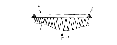
In order to have an optimum adaptation of the contour for
curved geometries in the intake path, one side of a
filter insert 10 is also correspondingly curved tv fit in
the exemplary embodiment of a filter element 9 in
accordance with Figure 4. This changing curve, fvr
example, can also be produced by correspondingly
directing a change in the distance between folds or
between the imprinting in the folding process.
In the exemplary embodiment in accordance with Figure 5,
a filter element 12 is provided with two foldedwregiona
13 and 14 which each fold xn different directions.
Figure 6 shows the filter element in accordance with
Figure 2, having a housing 20, in which the unfiltered
SUBSTITUTE SHEET (RULE 26)

'WO 98/47601 CA 0 2 2 8 7 4 5 5 19 9 9 -10 -18 PCT/1rp98/01541
- 6 -
air enters on the side according to arrow 21. Due to
this, an even volume flow can be achieved since, because
of the relatively large filter surface in the back region
4, a relatively large volume flow can occur here in spite
of the distance from the entrance point. This effect can
be seen with equal clarity in Figure 7, since here with
the filter surface becoming continuously smaller in
accordance with Figure 3, the volume flow can be reduced
in the front area at the entrance point and thus be
evened out-: . _.._.. _...._. _.. ___.___....___._ _._..._._._ _.__.____ -..
_... ___..._
SUBSTITUTE SHEET (RULE 26)

WO 98/47601 CA 0 2 2 8 7 4 5 5 19 9 9 -10 -18 PCTl~P9BI0154I
deference Numeral Liat
1 - Filter element


2 - Filter insert


3 - Fold region


4 - Fold region


- Fold region


6 - Seal


_... . _ .___ _.. __ _ _ _.... _. __.._.
7 _.. .__. __ ...__ _._ _____ ___ _. _ ..
- _ ._._ __. _ .
Filter element


a Filter insert
-


9 Filter element
-


Filter insert
-


11 Arrow (direction of flow)
-


12 Filter element
-


13 Fold region
-


14 Fold region
~


Housing
-


21 Arrow (raw air inflow)
-


SUBSTITUTE SHEET (RULE 26)

Representative Drawing
A single figure which represents the drawing illustrating the invention.
Administrative Status

For a clearer understanding of the status of the application/patent presented on this page, the site Disclaimer , as well as the definitions for Patent , Administrative Status , Maintenance Fee  and Payment History  should be consulted.

Administrative Status

Title Date
Forecasted Issue Date Unavailable
(86) PCT Filing Date 1998-04-15
(87) PCT Publication Date 1998-10-29
(85) National Entry 1999-10-18
Dead Application 2004-04-15

Abandonment History

Abandonment Date Reason Reinstatement Date
2003-04-15 FAILURE TO PAY APPLICATION MAINTENANCE FEE
2003-04-15 FAILURE TO REQUEST EXAMINATION

Payment History

Fee Type Anniversary Year Due Date Amount Paid Paid Date
Application Fee $300.00 1999-10-18
Registration of a document - section 124 $100.00 2000-02-15
Maintenance Fee - Application - New Act 2 2000-04-17 $100.00 2000-04-17
Maintenance Fee - Application - New Act 3 2001-04-16 $100.00 2001-03-27
Maintenance Fee - Application - New Act 4 2002-04-15 $100.00 2002-03-28
Owners on Record

Note: Records showing the ownership history in alphabetical order.

Current Owners on Record
FILTERWERK MANN & HUMMEL GMBH
Past Owners on Record
ERNST, VOLKER
KLOTZ, ARTHUR
SOMMER, BRUNO
Past Owners that do not appear in the "Owners on Record" listing will appear in other documentation within the application.
Documents

To view selected files, please enter reCAPTCHA code :


To view images, click a link in the Document Description column. To download the documents, select one or more checkboxes in the first column and then click the "Download Selected in PDF format (Zip Archive)" or the "Download Selected as Single PDF" button.

List of published and non-published patent-specific documents on the CPD .

If you have any difficulty accessing content, you can call the Client Service Centre at 1-866-997-1936 or send them an e-mail at CIPO Client Service Centre.


Document
Description 
Date
(yyyy-mm-dd) 
Number of pages   Size of Image (KB) 
Representative Drawing 1999-12-16 1 3
Abstract 1999-10-18 1 60
Description 1999-10-18 7 206
Drawings 1999-10-18 2 42
Claims 1999-10-18 4 90
Cover Page 1999-12-16 1 40
Correspondence 1999-11-24 2 2
Assignment 1999-10-18 3 84
PCT 1999-10-18 12 375
PCT 1999-10-19 6 194
Assignment 2000-02-15 2 66