Note: Descriptions are shown in the official language in which they were submitted.
. CA 02287742 1999-10-29
- 1 -
DESCRIPTION
"Process and burner for the partial oxidation of
hydrocarbons"
Field of the Invention
This invention relates to a process for the partial
oxidation of hydrocarbons to produce gaseous mixtures
comprising hydrogen and carbon monoxide, such as'synthesis
gas, and fuel or reducing gas.
In particular, this invention relates to a partial
oxidation process which comprises the steps of:
- feeding a hydrocarbon-comprising gas flow into a reaction
chamber;
- feeding a free oxygen-comprising gas flow into said
reaction chamber.
Throughout this specification and the appended claims, the
term: "hydrocarbon(s)", is used to denote a light and/or
heavy saturated and/or unsaturated hydrocarbon or
hydrocarbon mixtures (e.g. C1-C6); the expression
"hydrocarbon-comprising gas flow" is used to either denote
a fluid which contains gaseous hydrocarbons, such as
methane or natural gas, or a gaseous flow comprising
suspended solid combustible (e.g., coal dust or carbon
soot), or a gaseous flow comprising dispersed liquid
hydrocarbons (e.g., such light or heavy hydrocarbons as
naphtha or fuel oils).
In technical language, a gas flow which contains suspended
liquid hydrocarbons is usually referred to as a "mist",
while a gas flow which contains dispersed solid
hydrocarbons is termed a "smoke".
The invention also concerns a burner for implementing the
CA 02287742 1999-10-29
- 2 -
above process.
As is known, in the field of hydrocarbon partial oxidation
there exists a pressing demand for a high yield process
which can be easily implemented, and is both energy and
cost ef f icient .
Prior Art
To fill the above demand, processes have been developed
wherein the oxidation reaction is carried out at relatively
low temperatures, on the order of 1300 C, to significantly
reduce oxygen consumption and produce hydrogen and carbon
monoxide more economically.
A process of this kind is described in EP-A-0 276 538, for
example, wherein a hydrocarbon-comprising gas flow is first
mixed with a recovered solution comprising carbon soot and
then, following evaporation of the water contained in the
solution, mixed with oxygen in a reaction chamber at a
temperature in the 927 to 1316 C range, the combustion to
hydrogen and carbon monoxide taking place in that chamber.
While this prior process does afford a reduction in the
energy consumption in the reaction chamber, as well as in
the amount of oxygen to be fed into the reaction chamber,
it has a number of disadvantages, as listed herein below.
First of all, the carbon soot formed from the hydrocarbons
pyrolysed in the reaction chamber which, in the proximity
of the burner, get in contact with and are admixed to the
hot gases circulating within the chamber before they can be
suitably mixed with oxygen.
This production of carbon soot is mainly disadvantageous in
that a whole series of energy-intensive operations are made
necessary for separating the carbon soot from the reaction
products and feeding it back into the reaction chamber,
that a more complicated plant is needed for implementing
CA 02287742 1999-10-29
- 3 -
the process, and that capital and operating cost is high.
In addition, the carbon soot produced inside the reaction
chamber affects the overall yield of the partial oxidation
process, lowering the amount of hydrogen and carbon
monoxide which can be obtained per unit of burned
hydrocarbon, even where all the carbon soot produced and
returned to the burner is gasified.
On the other hand, prior processes effective to produce low
carbon soot concentrations involve operating the reaction
chamber at very high temperatures (on the order of 1400 C),
and therefore, at a high rate of oxygen consumption and low
conversion rate, for example as described in EP-A-0 276
538, page 2, lines 6-13.
In addition, the plants for implementing the aforementioned
processes have a disadvantage in that they are inflexible
in operation, being unable to accommodate the large load
variations to which the reactants fed into the reaction
chamber can be subjected, with the result that the
variations may trigger or boost the formation of carbon
soot.
It is on account of such limitations that prior art
processes for the partial oxidation of hydrocarbons have
involved large investment costs for their practical
implementation, thereby significantly penalizing the
production costs of such basic materials as hydrogen and
carbon monoxide, and this in the face of a growing demand
for them. Moreover, a pressing demand in the field for
hydrocarbon waste matter as the residues from distillation
processes in the oil industry to be burned off cannot be
satisfactorily filled by the aforementioned prior
processes.
Summary of the Invention
The underlying technical problem of this invention is to
CA 02287742 1999-10-29
- 4 -
provide an improved process for the partial oxidation of
hydrocarbons, at high yield, which allows a high production
of hydrogen and carbon monoxide per unit of burned
hydrocarbon, while drastically lowering the formation of
carbon soot even when operating at low temperatures, and is
flexible and easy to implement for a reasonably low energy
consumption and operating cost.
According to the present invention, the above problem is
solved by a process as indicated above, which is
characterized in that it further comprises the steps of:
- mixing and reacting a first portion of said free oxygen-
comprising gas flow with a first flow comprising reacted
gases circulating within said reaction chamber;
- mixing a second portion of said free oxygen-comprising
gas flow with said hydrocarbon-comprising gas flow in said
reaction chamber, obtaining a gas flow comprising both
hydrocarbons and free oxygen at least partly mixed
together;
- mixing and reacting said gas flow comprising both
hydrocarbons and free oxygen at least partly mixed together
with a second flow comprising reacted gases circulating
inside said reaction chamber, obtaining a gas flow
comprising hydrogen and carbon monoxide.
Throughout this specification and the appended claims, the
expression: "gas flow comprising reacted gases", is used to
denote a gas flow which contains H20, C02, trace
hydrocarbons, H2S, COS, and possibly N2 and Ar circulating
inside the reaction chamber, additionally to the partial
combustion products, i.e. CO and H2.
Advantageously, this invention enables the production of
hydrogen and carbon monoxide per unit of burned hydrocarbon
to be increased substantially relative to the prior art
processes.
CA 02287742 1999-10-29
- 5 -
In fact, thanks to the step of mixing a portion of the free
oxygen-comprising gas flow with the hydrocarbon-comprising
gas flow within the reaction chamber, before the last-
mentioned flow contacts the hot gases circulating inside
the chamber, the formation of carbon soot during the
following combustion step can be prevented or at least
reduced drastically.
In this way, the conversion yield of the hydrocarbons in
the reaction chamber will be only marginally - if not at
all - affected by the presence of carbon soot, thereby
ensuring an optimum production in hydrogen and carbon
monoxide.
It should be noted that thanks to the present invention the
formation of carbon soot in the reaction chamber can be
totally suppressed when the flow being processed comprises
gaseous hydrocarbons, and can be held down to a bare
minimum even where the gas flow comprises liquid and/or
solid hydrocarbons.
This result is advantageously obtainable even when
operating at low temperatures, preferably in the 950 to
1300 C range, and therefore, at a lower rate of oxygen
consumption and higher yield (increased production in CO
and H2) than the prior art.
As an example, for the partial oxidation of natural gas -
in a condition of total absence of carbon soot - the oxygen
requirement can be kept lower than 210 moles 02 per
kilomole of dry gas produced, which represents quite a
surprising achievement compared to the requirements for
oxygen of prior art processes.
In other words, the process of this invention prevents a
portion of the hydrocarbons flowing through the reaction
chamber from becoming mixed, in the absence of oxygen,
directly with the high-temperature (e.g., in the 1000 to
CA 02287742 1999-10-29
- 6 -
1400 C range) gases circulating within the chamber, causing
the hydrocarbons to be pyrolysed and carbon soot formed. On
the contrary, inside the reaction chamber, the hydrocarbons
are first suitably mixed with the free oxygen, and only
later contacted with the hot gases, which gases will then
trigger an advantageous combustion, rather than pyrolysis,
reaction of the reactants at least partially pre-mixed, to
produce hydrogen and carbon monoxide.
Furthermore, the process of this invention is quite simple,
economical and easy to implement, and involves neither a
high energy consumption nor high operating and maintenance
costs.
It should be noted that for the combustion of gaseous
hydrocarbons, such as methane or natural gas, the plant
implementing this process requires no carbon soot
separation and re-circulation section, thereby affording
major savings in investment cost and energy consumption
over prior art plants.
Advantageously, the present process has proved highly
flexible, since it can accommodate a range of different
operating conditions while retaining its high conversion
yield.
In particular, this process can be effectively applied even
in case of large variations in the rate of the flows fed to
the reaction chamber, such as in the 0.2 to 1.0 range
(ratio of minimum to maximum flow rate), without affecting
the conversion yield, a feature this one that cannot be
found in the prior art processes.
The portion of the free oxygen-comprising gas flow which
gets mixed, inside the reaction chamber, with the
hydrocarbon-comprising gas flow before contacting the re-
circulated reacted gases, referred to as the second portion
in the process according to the invention, advantageously
CA 02287742 1999-10-29
- 7 -
comprises as from 10 to 90 0, preferably 50 to 70%, of the
free oxygen-comprising gas flow.
In a particularly advantageous embodiment of the invention,
this process comprises the step of feeding the hydrocarbon-
comprising gas flow and the free oxygen-comprising gas flow
into the reaction chamber as respective, substantially
annular jets coaxial with each other.
Thus, the mixing of the hydrocarbons and free oxygen can
take place in a most effective and prompt manner inside the
reaction chamber.
Moreover, it has been found that to promote the mixing
action, it is more advantageous if the hydrocarbon-
comprising gas flow is fed to the reaction chamber
outwardly of and preferably at a higher velocity than the
free oxygen-comprising gas flow.
Preferably, according to the above embodiment, the process
of this invention further comprises the steps of:
- causing said free oxygen-comprising gas flow to flow
through a first, substantially cylindrical conduit of
predetermined length of a burner extending into said
reaction chamber;
- causing said hydrocarbon-comprising gas flow to flow
through a substantially annular free space defined between
said first conduit and a second outer conduit coaxial with
the first, said second conduit being longer than said first
conduit and defining inside said reaction chamber --
between one end of said second conduit and one end of said
first- conduit -- a mixing zone for said hydrocarbon-
comprising gas flow and said free oxygen-comprising gas
flow;
- directing said hydrocarbon-comprising gas flow from said
substantially annular free space to a region of said mixing
~ ..
, CA 02287742 1999-10-29
- 8 -
zone close to an inner wall of said second conduit;
- expanding and directing said free oxygen-comprising gas
flow exiting said first conduit toward said inner wall of
said second conduit in said mixing zone, thereby to mix and
react a first portion of said free oxygen-comprising gas
flow with a first flow comprising reacted gases circulating
inside said reaction chamber in a central zone thereof, and
to mix a second portion of said free oxygen-comprising gas
flow with said hydrocarbon-comprising gas flow obtaining a
gas flow comprising both hydrocarbons and free oxygen at
least partly mixed together.
In this way, a desired pre-mixing of the hydrocarbons and
the free oxygen can be achieved in the reaction chamber in
a highly effective and reliable manner, while preventing
during this step all contact of the hydrocarbons with the
reacted gases being circulated within the chamber.
Advantageously, this pre-mixing is made to occur at a part
of the inner wall of the feed conduit for the hydrocarbon-
comprising gas flow which extends between its end and the
end of the feed conduit for the free oxygen-comprising gas
flow.
In practice, part of the free oxygen-comprising flow is
advantageously caused to enter the hydrocarbon-comprising
flow, and a sufficient degree of mixing is attained in a
very small space to prevent - in case of gaseous
hydrocarbons - or drastically reduce - in case of liquid
and/or solid hydrocarbons - the formation of carbon soot
during the subsequent admixture to hot gases circulating
inside the reaction chamber.
In order to promote the expansion and transport of the free
oxygen-comprising gas flow toward the inner wall of the
second conduit in the mixing zone, this gas flow is
preferably caused to flow through the first conduit along a
CA 02287742 1999-10-29
- 9 -
spiral flowpath.
According to a further aspect of the invention, a burner
for the partial oxidation of hydrocarbons is provided which
comprises:
- a first, substantially cylindrical conduit of
predetermined length which defines on its interior a
circular passageway for feeding a free oxygen-comprising
gas flow into a reaction chamber outside the burner;
- a second conduit, outer of and coaxial with but longer
than the first, which defines a substantially annular free
space on its interior between said conduits, for feeding a
hydrocarbon-comprising gas flow into said reaction chamber;
and is characterized in that it further comprises:
- a mixing zone, wherein said hydrocarbon-comprising gas
flow is mixed with said free oxygen-comprising gas flow,
defined between respective ends of said first and second
conduit;
- means for directing said hydrocarbon-comprising gas flow
from said substantially annular free space to a region of
said mixing zone close to an inner wall of said second
conduit;
- means for expanding and directing said free oxygen-
comprising gas flow exiting said first conduit toward said
inner wall of said second conduit in said mixing zone,
thereby to mix and react a first portion of said free
oxygen-comprising gas flow with a first flow comprising
reacted gases circulating within said reaction chamber in a
central zone thereof, and to mix a second portion of said
free oxygen-comprising gas flow with said hydrocarbon-
comprising gas flow obtaining a gas flow comprising both
hydrocarbons and free oxygen at least partly mixed
together.
CA 02287742 1999-10-29
- 10 -
The features and advantages of the invention can be better
understood by reading the following description of an
embodiment of the inventive process, given by way of non-
limitative example with reference to the accompanying
drawings.
Brief Description of the Drawina,s
In the drawings:
- Figure 1 is a longitudinal section view through a model
which illustrates schematically the flowpaths of the
reactant and reacted gases within a hypothetical gas
generator when using the process for the partial oxidation
of hydrocarbons according to a preferred embodiment of the
present invention;
- Figure 2 shows schematically a plant for the partial
oxidation of gaseous hydrocarbons implementing the process
of the present invention;
- Figure 3 shows a longitudinal section view of a detail of
a burner according to a preferred embodiment of the present
invention;
- Figure 4 shows a longitudinal section view of a detail of
a burner according to another embodiment of the present
invention.
Detailed Description of a Pr f rr d E odim nt
To explain the principle and operation of this process for
the partial oxidation of hydrocarbons, reference is made to
Figure 1 which shows schematically the flowpaths of the
various gas flows through a hypothetical gas generator
operating in accordance with a preferred embodiment of the
invention.
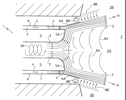
Schematically shown at 1 in Figure 1 is the end portion of
a burner extending into a reaction chamber generally
CA 02287742 1999-10-29
- 11 -
denoted by 2 of a hypothetical gas generator, and
specifically positioned in a central zone 2A of the chamber
2.
A free oxygen-comprising gas flow 3 and a hydrocarbon-
comprising gas flow 4 are fed into the zone 2A from the
burner 1 through respective conduits 5 and 6.
Specifically, the gas flows 3 and 4 are fed into the
reaction chamber 2 in the form of annular =jets, as
preferably obtained by causing the flow 3 to flow in a
spiral path through the conduit 5, as indicated in Figure 1
by a spiral arrow 3A, and the flow 4 to flow through an
annular free space 7 defined between the conduits 5 and 6.
Advantageously, by having the gas reactants fed to the
reaction chamber 2 as annular jets, the flow which contains
the reacted gases (e.g., hydrogen and carbon monoxide) from
the combustion of the hydrocarbons splits up naturally into
two flows 8A and 8B circulating within the central zone 2A
and a peripheral zone 2B, respectively, of the reaction
chamber 2.
Since the reacted gas-comprising flows 8A and 8B are quite
hot, being generally at a temperature above 1000 C, their
contact or admixture to the gaseous reactants flows causes
immediate combustion with flame formation in the instance
of the free oxygen-comprising flow 3, and pyrolysis of the
hydrocarbons from the hydrocarbon-comprising flow 4.
To prevent such hydrocarbon pyrolysis from occurring, which
is responsible for the formation of carbon soot in the
reaction chamber 2, the process of the present invention
comprises the step of mixing at least in part the
hydrocarbons with the free oxygen prior to their admixture
to the hot burned gases circulating inside the reaction
chamber 2.
For the purpose, the conduit 6 is made longer than the
CA 02287742 1999-10-29
- 12 -
conduit 5 and is formed with a frusto-conical tip 6A which
extends into the reaction chamber 2.
Defined inside this tip 6A, specifically at a location near
the inner wall of the conduit 6, is a mixing zone for the
hydrocarbon-comprising gas flow 4 and the free oxygen-
comprising gas flow 3 which is undisturbed by the reacted
gas flow, specifically the flow 8B.
To promote an effective prompt mixing of the hydrocarbons
with the free oxygen, the conduit 5 is provided with an
expansion cone 5A at its end.
It is only after the hydrocarbons and the free oxygen have
been at least partially mixed together obtaining a gas flow
which contains hydrocarbons and free oxygen, generally
denoted by 9, that the latter is mixed with the flow 8B and
reacted to produce hydrogen and carbon monoxide.
The particular annular jet type of feed pattern provided
for the reactants, with the free oxygen jet being flowed
within the hydrocarbon jet, in combination with the central
circulation of part of the reacted gases, advantageously
allows some of the free oxygen to be mixed and then reacted
with the reacted gases circulating in the central zone 2A
of the reaction chamber 2, resulting in that the flame
generated inside the chamber 2 is rooted in a stable and
reliable manner centrally near the free oxygen inflow zone
to the reaction chamber 2.
Furthermore, by flowing the oxygen centrally and the
hydrocarbons outwardly, the tip 6A on the outer conduit 6
of the burner 1 can be used for mixing the reactants while
protecting the hydrocarbons from the hot gases circulating
in the peripheral zone 2B of the reaction chamber, as well
as from the flame issuing from the core region of the
burner 1.
To fully explain the features of this partial oxidation
CA 02287742 1999-10-29
- 13 -
process, it should be pointed out that it is an entirely
different process from the prior art mixing or diffusing
processes.
The term mixing process means a process whereby the
hydrocarbon-comprising gas flow and the free oxygen-
comprising gas flow are mixed together - usually within the
burner - before they are fed into the reaction chamber.
This mixing may be carried out either in a- thorough
fashion, that is until a flow with uniform concentrations
of oxygen and hydrocarbons is obtained, or a partial
fashion, that is with a concentrations field in the feed
flow to the reaction chamber which will be dependent on the
mixing procedure and extent.
A process of this kind is, for example, disclosed in EP-A-0
098 043.
Although in theory the mixing process is effective to keep
down the production of carbon soot, it has found no
practical application because of its inherently dangerous
nature.
In fact, in operation of the gas generator, the risk of a
backfire in the burner, i.e. of the oxidation reaction
being triggered while still in the burner conduits, is
always latent and may result in premature wear of the same.
This is a near-uncontrollable phenomenon due to the high
flammability of the hydrocarbon/oxygen mix, the high
operating temperatures, and possible variations in the
reactants flow rates.
The'term diffusion process means a process whereby the
hydrocarbon-comprising gas flow and the free oxygen-
comprising gas flow are instead fed separately into the
reaction chamber, where they are mixed simultaneously
together and with the reacted gases present and circulating
in the chamber.
CA 02287742 1999-10-29
- 14 -
A process of this kind is, for example, that disclosed in
the above-mentioned EP-A-0 276 538.
The drawbacks of this conventional process have been
described hereinabove in connection with the state of the
art; in particular, its high rate of carbon soot production
is noteworthy, which is due to the high-temperature
recirculated gases contacting, inside the reaction chamber,
incoming hydrocarbons which have had no chance of getting
suitably mixed with the free oxygen.
In relation to the present invention, it should be stressed
that the provision of a preliminary mixing step within the
reaction chamber for the hydrocarbon-comprising gas flow
with the free oxygen-comprising gas flow, before the
hydrocarbons can contact the reacted gases, contradicts the
prior art teachings that the reactants should either be
mixed before introducing them into the reaction chamber or
only after their introduction simultaneously with the
reacted gases.
It is the research work carried out by the Applicant that
led to a partial oxidation of hydrocarbons at a high yield
with no or markedly reduced production of carbon soot.
In essence, it can be said that the inventive process
reflects a sort of combination of the aforesaid processes,
but without their problems and with a substantially higher
yield of the conversion to hydrogen and carbon monoxide
under like conditions of operation.
In Figure 2, generally shown at 10 is a plant for the
partial oxidation of gaseous hydrocarbons according to the
present invention.
Advantageously, the plant 10 comprises two pre-heaters 11
and 12, respectively for pre-heating a hydrocarbon-
comprising gas flow and a free oxygen-comprising gas flow,
a gas generator 13 for partially oxidizing the
CA 02287742 1999-10-29
- 15 -
hydrocarbons, and a boiler 24 for recovering the sensible
heat from the resultant gas flow comprising hydrogen and
carbon monoxide.
The pre-heaters 11 and 12 and the boiler 24 are
conventional and no further described hereinafter.
The gas generator 13 comprises a nozzle 14 and a shell 15
which is lined with a high temperature-resistant refractory
material, not shown because conventional, for protection of
its inner walls.
The shell 15 interior forms a reaction chamber 16 wherein
the combustion of the hydrocarbons with the oxygen takes
place.
A burner 17 extends through the nozzle 14 such that its end
portion opens to the interior of the reaction chamber 16.
The hydrocarbon-comprising gas flow is fed to the gas
generator 13 by means of a conduit 18 passing through the
pre-heater 12.
Likewise, the free oxygen-comprising gas flow is fed to the
gas generator 13 by means of a conduit 19 passing through
the pre-heater 11.
In the example of Figure 1, the hydrocarbon-comprising gas
flow comprises essentially gaseous hydrocarbons, such as
natural gas or methane and mixtures thereof, and mixtures
of these gases with such carrier gases as steam or inert
gases.
In addition, the hydrocarbon-comprising gas flow may
include predetermined amounts of gases from industrial
plants, e.g. from the synthesis loop of an ammonia plant.
Alternatively, the hydrocarbon-comprising gas flow may
comprise a carrier gas - such as an inert gas or steam -
having a finely divided liquid or solid fuel respectively
CA 02287742 2007-12-21
- 16 -
dispersed or suspended therein.
The expression "finely divided" is used here to denote
droplets or solid particles of an average size in the 0.01
to 1.0 mm range.
Examples of suitable liquid fuels for use in the process of
the present invention include: fuel oil, diesel oil,
naphtha, crude oil, or residues from the distillation
sections of oil plants, and mixtures thereof. Examples of
solid fuels include: asphalts and coals, and mixtures
thereof.
Where liquid or solid hydrocarbons are used, the plant of
Figure 1 should include a processing and recovery section,
not shown, for any carbon soot produced.
The free oxygen-comprising gas flow generally comprises a
gas selected from a group including air, enriched air with
oxygen, i.e. air having an oxygen content in excess of 21
molar percent, substantially pure oxygen, i.e. a gas with
an oxygen content of no less than 95 molar percent, and
mixtures thereof.
The gas flows are heated independently through the pre-
heaters 11 and 12, as by convection to a temperature which is
usually lower than about 600 C, preparatory to feeding the
gas flows into the gas generator 13.
The plant 10 implementing the process of this invention may
also be provided with a conventional desulphurization unit,
not shown in Figure 2, for removing any trace sulphur from
the hydrocarbon-comprising gas flow.
The working pressure inside the gas generator 13 is
generally in the range of 1 to 150 bar.
After pre-heating, the gas flows are fed into the gas
generator 13 or, more precisely, into the reaction chamber
CA 02287742 1999-10-29
- 17 -
16 through respective conduits of the burner 17.
In particular, the free oxygen-comprising gas flow is fed
into the reaction chamber 16 through a circular passageway
defined inside a first, substantially cylindrical conduit
20 having a predetermined length.
The hydrocarbon-comprising gas flow is fed into the
reaction chamber 16 through an annular free space formed
between the first conduit 20 and a second outer conduit 21,
coaxial with but longer than the first.
Advantageously, the burner 17 further comprises a mixing
zone 22 defined inside the reaction chamber 16 between
respective ends of the conduits 20 and 21, where the
reactants are pre-mixed before being admixed to the flow of
reacted gases circulating in the chamber.
Immediately upon leaving the mixing zone 22, in the
reaction chamber 16, the mixing of reactants is completed
and the subsequent partial oxidation reaction of the
hydrocarbons carried out, obtaining a gas flow which
contains hydrogen and carbon monoxide and will leave the
gas generator 13 via the conduit 23.
The oxygen-to-hydrocarbon molar ratio may vary between 0.5
and 1.2, according to the degree of purity of the free
oxygen-comprising gas flow, the extent of the reactant pre-
heating, and the type of the hydrocarbon flow mix.
The reaction products are subsequently flowed - again via
the conduit 23 - through the boiler 24 where they are
cooled by indirect exchange of heat with a water flow, to
release steam at an elevated thermal level (e.g. in the 20
to 100 bar range).
For the purpose, conduits 25 and 26 are provided for
respectively supplying water into the boiler 24 and
exhausting steam therefrom.
CA 02287742 1999-10-29
- 18 -
The provision of the boiler 24 in the plant of Figure 2
depends basically on the nature of the fuel being handled.
Where the latter yields a raw gas comprising hydrogen and
carbon monoxide with a high content of impurities, it is
cooled by a simple quenching device using water (not
shown).
The plant 10 just described can advantageously implement
the process of this invention, which process is
characterized in particular by the fact of comprising the
steps of mixing and reacting a first portion of the free
oxygen-comprising gas flow with a first flow comprising
reacted gases circulating inside the reaction chamber 16,
and mixing a second portion of the free oxygen-comprising
gas flow with the hydrocarbon-comprising gas flow in the
mixing zone 22 of the reaction chamber 16, to obtain a gas
flow comprising both hydrocarbons and free oxygen at least
partly mixed together, and of mixing and reacting the gas
flow thus obtained in the zone 22 with a second flow
comprising reacted gases circulating inside the reaction
chamber 16 to obtain a gas flow comprising hydrogen and
carbon monoxide.
In this way, the production of carbon soot can be
suppressed or significantly attenuated even when operating
at low temperatures (below 1300 C), so that the consumption
of oxygen can advantageously be limited and the output of
hydrogen and carbon monoxide improved accordingly.
As said before, the process can be carried out effectively
even with significant variations occurring in the flow
rates of the reactant flows, without this affecting
negatively the conversion yield.
It should be noted that the process of this invention can
suppress the production of carbon soot completely where
flows comprising gaseous hydrocarbons are handled.
CA 02287742 1999-10-29
- 19 -
The absence of carbon soot is essentially dependent on the
reactant pre-mixing step within the reaction chamber 16
and, therefore, on the presence of free oxygen in the
hydrocarbon-comprising gas flow during the subsequent
mixing with the hot circulating gases.
To promote a thorough mixing of the reactants and their
subsequent combustion, it has been found advantageous to
deliver the hydrocarbon-comprising gas flow to the reaction
chamber 17 at a velocity in the range of 30 to' 300 m/s,
preferably 60 to 180 m/s, and the free oxygen-comprising
gas flow at a velocity in the range of 10 to 100 m/s,
preferably 20 to 60 m/s.
In a specially preferred and advantageous embodiment of the
process according to the present invention, the process
further comprises the steps of causing the free oxygen-
comprising gas flow to flow through the first conduit 20,
causing the hydrocarbon-comprising gas flow to flow through
the annular free space defined between the first conduit 20
and the second conduit 21, directing the hydrocarbon-
comprising gas flow from the annular free space to the
mixing zone 22 at a location close to an inner wall 27 of
the second conduit 21, and expanding and directing the free
oxygen-comprising gas flow exiting the first conduit 20
toward the inner wall 27 of the second conduit 21 in the
mixing zone 22.
In this way, the free oxygen and the hydrocarbons can be
suitably pre-mixed in a quick efficient manner, while
protecting the hydrocarbons from the hot gases circulating
in the reaction chamber 16, as well as from the flame
issuing from the core end of the burner 17 within the
chamber 16.
As shown in Figure 3, the burner 17 advantageously
comprises for this purpose - additionally to the conduits
20 and 21 - suitable means for directing the hydrocarbon-
CA 02287742 1999-10-29
- 20 -
comprising gas flow from the annular free space 31 to the
mixing zone 22 in the reaction chamber 17, at a location
close to the inner wall 27 of the second conduit 21, and
comprises suitable means for expanding and directing the
free oxygen-comprising gas flow exiting the first conduit
20 toward the inner wall 27 of the second conduit 21, in
the mixing zone 22.
Figure 3 is a detail view of the burner 17, specifically to
illustrate the burner end portion, according to a preferred
embodiment of the present invention.
In this figure, structurally and functionally equivalent
items to those shown in Figure 2 have the same reference
numerals and will be no further described.
It should be noted that the conduits 20 and 21 of the
burner 17 are of hollow construction for a more effective
cooling thereof, as explained hereinafter.
The end of the first conduit 20, the circular passageway
formed inside the first conduit 20, and the annular free
space defined between the second conduit 21 and the first
conduit 20 of the burner 17 are denoted in Figure 3 by the
reference numerals 28, 29 and 30, respectively.
Advantageously, in order to speed up the hydrocarbon-
comprising gas flow sweeping across the inner wall 27 of
the second conduit 21 at the mixing zone 22, the means for
directing the hydrocarbon-comprising gas flow comprise an
annular opening 31 thinner than the annular free space 30,
which is formed at the end 28 of the first conduit 20,
between the free space 30 and the mixing zone 22.
The means for expanding and directing the free oxygen-
comprising gas flow advantageously comprise, located close
to the end 28 of the first conduit 20, a portion of this
conduit which suitably flares out toward the inner wall 27
of the second conduit 21 so as to define, at said end 28, a
CA 02287742 1999-10-29
- 21 -
gas outflow opening 33 between the passageway 29 and the
mixing zone 22 which has a larger diameter than the rest of
the first conduit 20.
Thus, the free oxygen-comprising gas flow will be deflected
and expanded toward the wall 27 of the second conduit 21,
thereby ensuring optimum penetration of this flow into the
hydrocarbon flow.
The diameter of the opening 33 may vary between 1:25 and 10
times the diameter of the first conduit 20 upstream of the
portion 32, and satisfactory results have been obtained in
the 2 to 4 times range.
As can be seen from figure 3, the flared portion 32 of the
first conduit 20 is advantageously curved to allow a
controlled and as even as possible expansion of the oxygen-
comprising gas flow, while assisting in directing it toward
the inner wall 27 of the second conduit 21 at the mixing
zone 22.
In accordance with the process of this invention, the free
oxygen-comprising gas flow is advantageously caused to flow
from the passageway 29 to the mixing zone 22 through the
outlet opening 33 of the first conduit 20. In parallel
therewith, the hydrocarbon-comprising gas flow is
advantageously flowed from the free space 30 to the mixing
zone 22 through the annular opening 31 defined in the
reaction chamber 16 between the end 28 of the first conduit
20 and the end 34 of the second conduit 21, proximate to
its inner wall 27.
Advantageously, according to a specially preferred aspect
of the present invention, the portion 32 extends
continuously from an inner wall 20A to an outer wall 20B of
the conduit 20, at a constant slope angle from the end of
the inner wall 20A to the end of the outer wall 20B, or
preferably, at a slope angle which varies continuously from
CA 02287742 1999-10-29
- 22 -
00 at the end of the inner wall 20A to at most 90 at the
end of the outer wall 20B. Thus, the end of the outer wall
20B forms the end 28 of the conduit 20, and the end of the
outer wall 20A is coincident with the cylindrical end of
the conduit 20.
This unique configuration of the portion 32 of the conduit
20 for feeding the free oxygen-comprising gas flow into the
reaction chamber 16 allows the rate of thermal wear of the
end portion of that conduit near the end 28 to be slowed
down considerably
In fact, a study by the Applicant has shown that the
absence of any sharp corners in the portion 32, that is in
the portion connecting the inner wall 20A to the outer wall
20B of the conduit 20, is effective to prevent formation of
whirls or stagnant regions in the free oxygen-comprising
gas flow at that portion 32, thereby guarding it against
premature thermal wear. On the contrary, according to the
invention, the oxygen advantageously moves in a continuous
linear flow along the portion 32 before leaving the conduit
20, while maybe cooling its surface.
In particular, the initial contact of the hydrocarbon-
comprising gas flow flowing through the conduit 21 with the
free oxygen-comprising gas flow flowing through the conduit
20 is advantageously made to occur at the end 28 of the
conduit 20.
It should be noted that the oxygen feed conduits of the
burners had a life span of no more than a few months in
prior art arrangements, whereupon they had to be replaced
and_the whole plant stopped in consequence.
Thanks to the present invention, the life expectation of
the end portion of such conduits is much longer, and this
can last several years between replacements, so that the
plant can be run consecutively for long time periods. In
CA 02287742 1999-10-29
- 23 -
this way, the plant maintenance and operating costs, and
production losses, can be reduced.
In particular, the curved shape of the portion 32 (shown in
Figure 3) ensures optimum results as regards durability of
the conduit 20.
In this respect, satisfactory results have been obtained
especially by adopting a slope angle of 30 to 90 ,
preferably 45 to 80 , for the portion 32.
According to a particularly advantageous aspect of the
inventive burner, the length of the inner wall 27 of the
second conduit 21 at the mixing zone 22, as measured
between the respective ends 28 and 34 of the conduits 20
and 21, is set by the thickness dimension (cross-sectional
area) of the annular opening 31 between the conduits 20 and
21.
Preferably, this length will be 5 to 15 times said
thickness dimension.
So doing, it is possible to adjust in an optimum manner
(neither too much nor too little) for a desired amount of
reactants pre-mixing.
According to an advantageous further aspect of the
inventive burner, the inner wall 27 of the second conduit
21 at the mixing zone 22 has a diameter which increases
toward the end 34, so that the mixing zone 22 takes a
frusto-conical shape.
In particular, the slope angle of the inner wall 27 of the
second conduit 21 in the mixing zone 22 is advantageously
in the range of 0 to 60 , preferably 10 to 30 , from the
longitudinal axis 35.
The aforesaid frusto-conical shape of the mixing zone 22,
with its major circumference being defined by the opening
CA 02287742 1999-10-29
- 24 -
36 of the burner 17 and its minor circumference defined by
the inner wall 27 of the second conduit 21 at the end 28 of
the first conduit 20, serves essentially a dual function of
keeping the hydrocarbon-comprising gas flow away from the
central flame and of enlarging the width of the inner
recovery zone (reference 2A, Figure 1), so as to achieve
full stabilization (rooting) for the flame.
Advantageously, the burner 17 can also include suitable
means for forcing upon the free oxygen-comprising gas flow
a spiral flowpath through the first conduit 20, to further
promote the expansion and transport of that flow toward the
inner wall 27 of the second conduit 21 at the mixing zone
22.
In the example of Figure 3, these means comprise one or
more suitably shaped vanes 37, optionally set at an angle
to the longitudinal axis 35, located proximate to one end
of a rod-like holder, represented in Figure 3 by the
conduit 38 which extends for a predetermined length
coaxially through the passageway 29 defined by the conduit
20.
The vanes 37 are shaped to impart a desired swirling motion
to the gas flow. Preferably, a plurality of such vanes 37
are arranged helically around the conduit 38.
In an alternative embodiment, not shown, these means may be
a suitable shaping of either the conduit 20 or the conduit
38.
In Figure 3, the conduit 38 is shown open because it
advantageously serves the additional function of affording,
in a simple reliable manner, control on the reacted gas-
comprising gas flow which is circulated centrally of the
reaction chamber 16, as well as on the flame rooting
position.
To this aim, a part of the free oxygen-comprising gas flow
CA 02287742 1999-10-29
- 25 -
is caused to flow through the interior of the conduit 38 in
a true axial flow which will oppose the reacted gas flow
sweeping across the central conduit 20.
Alternatively, the conduit 38 could be used, during the
refractory heating step inside the gas generator, to
deliver fuel to the reaction chamber 16. In this way, the
burner 17 can be used advantageously for the gas generator
heating operation as well, doing away with the need for an
additional purposely provided burner.
Indicated at 39 and 40, moreover, are recesses in the walls
of the first conduit 20 and the second conduit 21 for
admitting a liquid coolant, preferably water.
Thus, the temperature of the conduits 20 and 21 can be
effectively controlled, particularly at their ends 28 and
34, to prevent overheating and likely rapid deterioration
thereof.
Under certain conditions of operating temperature, this
cooling can be forfeited.
Figure 4 is a detail view of a burner according to a
further embodiment of this invention.
In the figure, structurally and functionally equivalent
items of the burner 17 to those shown in Figure 3 are
denoted by the same references and will not be further
described.
In accordance with this embodiment of the burner 17, the
same protective effect as provided by the inner wall 27 of
the_second conduit 21 at the mixing zone 22 (Figure 3), is
now provided by a substantially annular jet, e.g. of steam
or inert gases, supplied to the reaction chamber 16
outwardly of the hydrocarbon-comprising flow.
This additional or protective flow, as indicated by arrows
CA 02287742 1999-10-29
- 26 -
41 in Figure 4, is effective (similar to the wall 27 in
Figure 3) to isolate the mixing zone 22 from the reacted
gas-comprising flow (arrows 42) circulating in the
peripheral zone of the reaction chamber 16. The arrows 42
correspond to the arrows 8B of Figure 1.
According to this embodiment, instead of increasing the
length of the second conduit 21 relative to the first
conduit 20, suitable means are provided for letting in a
protective gas flow (arrows 41) comprised, preferably, of
steam and/or inert gases.
For example, these inlet means may be a third conduit 43
placed externally of and coaxially with the conduits 20 and
21. The numeral 44 denotes an annular free space defined
between the third conduit 43 and the second conduit 21 of
the burner 17.
In accordance with the process of this particular
embodiment of the invention, a gas flow comprising steam
and/or inert gases is caused to flow through the conduit
43, to enter the reaction chamber 16 in the form of a
substantially annular jet that defines a mixing zone 22 on
its interior. At the same time, the free oxygen-comprising
gas flow is caused to flow through the passageway 29 to the
mixing zone 22 via the outlet opening 33 of the first
conduit 20, and in parallel therewith, the hydrocarbon-
comprising gas flow is caused to flow through the free
space 30 to the mixing zone 22 via the annular opening 31
defined between the end 28 of the first conduit 20 and the
end 34 of the second conduit 21.
The_process for the partial oxidation of hydrocarbons, and
in particular the pre-mixing in the zone 22 of the
hydrocarbon-comprising gas flow with a second portion of
the free oxygen-comprising gas flow, in a condition of no
contact with the hot gases circulating in the reaction
chamber 16, are carried out in a similar manner, and afford
CA 02287742 1999-10-29
- 27 -
the same advantages, as discussed hereinabove in relation
to the previous figures.
In the example of Figure 4, the gas flow 41 comprising
steam and/or inert gases, by sweeping across the outer wall
of the conduit 21, has advantageously a cooling effect on
that conduit, particularly at its end. Accordingly, the
conduit 21 can be made of solid construction rather than
hollow as shown in Figure 3.
*** * ***
The manifold advantages afforded by the process of this
invention can be fully appreciated from the foregoing
description; in particular, a reaction of partial oxidation
of the hydrocarbons can be performed:
- in the complete absence of carbon soot, for gaseous
hydrocarbons, with a simplified process-implementing plant;
- with a drastic reduction of carbon soot, in the instance
of liquid or solid hydrocarbons;
- at low rates of oxygen consumption and a high yield of
conversion to hydrogen and carbon monoxide per unit of
burned hydrocarbon; and
- with longer burner life expectations.