Note: Descriptions are shown in the official language in which they were submitted.
CA 02288037 1999-10-22
WO 99/42181 PCT/US99/04027
- 1 -
FIRE-EXTINGUISFiER NOZZLE
Background of the Invention
~
The invention relates to nozzles used to dispense
fluid from fire-extinguisher systems. Fire-extinguisher
systems are commonly installed in commercial settings
such as in commercial kitchens or restaurants. These
systems dispense extinguishing fluid according to design
specifications. Nozzles are attached to the system that
will spray fluid in a pattern, known as a spray profile,
that is consistent with the specification. When not in
use, the nozzles are exposed to debris, such as dirt and
grease, that can obstruct the flow passage of the nozzle.
It is known to place a plastic cap over the tip of
the nozzle to prevent debris from entering the nozzle.
When the system is activated, pressure builds from within
the nozzle and pushes the cap off the tip of the nozzle
allowing fluid to be dispensed.
Summary of the Invention
According to the invention a nozzle includes a
housing defining a fluid passage. A member, e.g., a
foil, is positioned to block the fluid passage when the
nozzle is not spraying fluid. A retainer attached to the
housing retains the member in the disposed position.
Preferred embodiments of this aspect of the
invention may include one or more of the following
features. The foil bursts under the flow of fluid. The
retainer is threaded onto the housing. The housing is
formed as a single piece.
In another aspect of the invention, a surface of
the housing of the nozzle contains one or more
identifying marks, e.g., circumferential grooves. The
number of marks indicates a spray profile of the nozzle.
According to another aspect of the invention, a
nozzle includes a housing defining a fluid passage, and a
CA 02288037 2007-03-20
-2-
member disposed in the fluid passage for blocking the
fluid passage when the nozzle is not spraying fluid. The
member is constructed to burst under the flow of fluid.
According to another aspect of the invention, a
method of preventing debris form entering a nozzle
includes placing a member within a fluid passage of the
nozzle to block the fluid passage when the nozzle is not
spraying fluid. The member is burst by flowing fluid
into the nozzle to allow delivery of fluid through the
nozzle.
Among other advantages, the member prevents
debris, especially kitchen grease, from clogging the
fluid passage of the nozzle when the nozzle is not
spraying fluid. The member is capable of quickly
bursting when the nozzle is activated and fluid begins to
flow. However, the member is retained against the nozzle
and will not separate from the tip of the nozzle over
time. The marks on the nozzle allow an operator to
easily identify the type .of spray profile that will be
produced by the nozzle.
In another aspect, the invention provides a nozzle
comprising:
a housing defining a fluid passage including a fluid
outlet for delivery of fire-extinguishing fluid to a fire,
the housing being configured for releasable attachment to a
fire-extinguishing system;
a vane for controlling the spray profile of fluid exiting
from the nozzle;
a member disposed in a position for blocking the fluid
passage when the nozzle is not delivering fire-
extinguishing fluid; and
a retainer attached to the housing for retaining the
member in the disposed position.
CA 02288037 2007-03-20
-2a-
Brief Description of the Drawings
FIG. 1 is a partial cross-sectional view of a
fire-extinguisher nozzle.
FIG. 2 is an exploded cross-sectional view of the
fire-extinguisher nozzle shown in FIG. 1.
FIG. 3 is a partial cross-sectional view of an
additional embodiment of a fire-extinguisher nozzle.
Description of the Preferred Embodiments
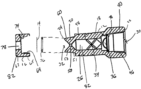
Referring to FIGS. 1 and 2, a fire-extinguisher
nozzle 10 suitable for dispensing fluid, especially
water, from a fire extinguishing system includes a
housing 12, a foil 14, and a foil retainer 16. Foil 14
prevents debris from entering the nozzle and bursts under
the flow of extinguisher fluid. Housing 12 is a
generally cylindrical structure constructed from a-single
~
CA 02288037 1999-10-22
= õ
WO 99/42181 PCT/US99/04027
- 3 -
piece of material. and has openings 30, 32 at a proximal
end 22 and a distal end 24, respectively. Housing 12 has
two distinct regions: a nozzle body 18 that lies toward
the proximal end 22 of housing 12, and a nozzle tip 20
5=that lies toward the distal end 24 of housing 12.
Housing 12 has an internal passageway 26 extending
through nozzle body 18 and nozzle tip 20, and terminating
at proximal end opening 30 and distal end opening 32.
Nozzle body 18 houses a vane 34 and a cup strainer
36 positioned within internal passageway 26. Vane 34
spans across internal passageway 26 and affects the flow
of fluid through internal passageway 26. Cup strainer 36
is a porous mesh that lies closer to proximal end 22 than
vane 34 and completely covers internal passageway 26.
Cup strainer 36 is held in place by, e.g., a retaining
ring 38. Nozzle body 18 has a hexagonal head 40 at
proximal end 22 that can accommodate a wrench or other
tool for attaching nozzle 10 to an extinguisher system.
Hexagonal head 40 has an internal thread 46.
A set of rings 48 are engraved into the outer
surface of nozzle body 18 to a depth of, e.g., 0.795 mm
(0.031"). The number of rings informs the operator of
the particular spray profile (described below) produced
by nozzle 10.
Nozzle tip 20 has a constricted region 50 where
the diameter of internal passageway 26 is reduced.
Moving in a direction from proximal end 22 to distal end
24, the diameter of passageway 26 first decreases in a
proximal section 51 of constricted region 50 and then
increases in a distal section 53 of constricted region
50.
Nozzle tip 20 includes an external thread 60.
Retainer 16 has a first section 65 including an internal
thread 64 for attaching retainer 16 to nozzle tip 20. A
second section of retainer 16 has a passage 78. A lip 74
CA 02288037 1999-10-22
WO 99/42181 PCT/US99/04027
- 4 -
is defined by section 67. Lip 74 abuts distal end 24 of
housing 12 when retainer 16 is attached to nozzle tip 20
as shown in FIG. 1: When retainer 16 is attached to
nozzle tip 20, passage 78 and internal passageway 26
combine to form a fluid passage 82. Foil 14 lies against lip 74 and within
fluid
passage 82. A mounting disk 76, e.g. a washer,
positioned between foil 14 and distal end 24 of housing
12 supports the foil. When retainer 16 is attached to
nozzle tip 20, foil 14 completely covers opening 32 at
distal end 24. This configuration prevents debris such
as kitchen grease, which collects on nozzle 10 when the
extinguisher system is idle, from clogging internal
passageway 26.
As an example, nozzle 10 is constructed in the
following configuration. Housing 12 has a length of
45.67 mm (1.78111) and is constructed of brass with
nickel-chrome plating. Vane 34 is constructed of brass.
Cup strainer 36 is constructed of a stainless steel mesh.
Retaining ring 38 is also constructed of stainless steel.
Retainer 16 is constructed of brass with a nickel-chrome
plating. Foil 14 is composed of a thin, pliable metal
such as tin, and mounting disk 76 is brass.
In operation, with nozzle 10 attached to a fire-
extinguishing system, e.g., a system installed in a
commercial kitchen, when a fire is sensed, a
extinguishing fluid flows though fluid passage 82 and is
dispensed from distal end 24 of housing 12. Foil 14 is a
thin, pliable material which bursts quickly under the
pressure formed when the extinguisher system is activated
and fluid begins to flow through internal passageway 26.
However, because foil 14 is retained against housing 12
by retainer 16, foil 14 will not separate from housing 12 prior to or during
activation of the extinguishing
system.
CA 02288037 1999-10-22
WO 99/42181 PCT/US99/04027
- 5 -
As fluid flows through internal passageway 26, cup
strainer 36, which lies upstream of vane 34, filters out
debris in the fluid, e.g., rust or minerals, that may
lodge against vane 34 or constricted region 50. Vane 34
disrupts the continuous fluid flow to create a flow of
fluid droplets. The fluid droplets pass through
constricted region 50 which causes the droplets to be
dispensed in a spray profile. It is known to configure
vane 34 to provide a particular droplet size that, when
coupled with the configuration of constricted region 50,
determines the spray profile.
Rings 48 are engraved in patterns which correspond
to the particular spray profile of the nozzle. Rings 48
allow a nozzle 10 having a particular spray profile to be
easily identified, e.g., for installation or replacement
in an extinguishing system according to the design
specifications. For example, as shown in FIG. 1, four
rings 48 correspond to a "full cone" spray profile of
90.0 (+/- 100) at 100 pounds/square inch (psi) in nozzle
10 having a narrow diameter 56 of 1.667 mm (0.065") and a
flow capacity of 1.00 gallon/minute (gpm) (+/- 5%); as
shown in FIG. 3, three rings 48 correspond to a "full
cone" spray profile of 46.0 (+/- 10 ) at 100 psi in
nozzle 10 having a narrow diameter 56 of 1.590 mm
(0.062") and a flow capacity of 0.92 gpm (+/- 5%); two
rings 48 correspond to a "full cone" spray profile of
30.0 (+/- 10 ) at 100 psi in nozzle 10 having a narrow
diameter 56 of 2.487 mm (0.09711) and a flow capacity of
2.20 gpm (+/- 5%); one ring 48 corresponds to a "full
cone" spray profile of 46.0 (+/- 10 ) at 100 psi in
nozzle 10 having a narrow diameter 56 of 1.667 mm
(0.065") and a flow capacity of 1.00 gpm (+/- 5%); no
rings 48 correspond to a "full cone" spray profile of
61.0 (+/- 10 ) at 100 psi in nozzle 10 having a narrow
CA 02288037 1999-10-22
WO 99/42181 PCT/US99/04027
- 6 -
diameter 56 of 2.897 mm (0.113") and a flow capacity of
3.00 gpm (+/- 5%) .
Other embodiments are within the scope of the
following claims.
For example, other conventions may be chosen to
correlate a particular ring pattern to a particular spray
profile. Other visual marks, such as a number of painted
lines, may be used to signify a particular spray pattern.
In addition, the marks may signify more than the spray
profile, e.g., capacity or size. The foil and retainer
may also take on additional configurations. For example,
the foil may be a plastic membrane, or the retainer may
be an adhesive substance.