Note: Descriptions are shown in the official language in which they were submitted.
CA 02288051 2005-10-04
Bale collector
The invention relates to a bale collector which comprises
a mobile frame. The bale delivery device behind which the
baler collector is connected is, for example, a baler or a
wrapping device for wrapping each bale in a film.
A bale collector according to the preamble of claim 1 is
disclosed by EP-A-O 110 056. With the known bale collector
the horizontal axis for tilting the rotatable bale bearing
part is arranged in front of wheels of the bale collector,
close to the bale delivery outlet of the bale delivery device.
The rotatable bearing part can tilt from a horizontal position
downwards deeper between the wheels until a rear part touches
the ground. Tilting or rotating of the rotatable bale bearing
part is established by the use of a cylinder. The non-return
element comprises a portal with an upper transverse bar. The
portal is maintained in a rest position by spring means such
that, in the rest position, a distance between the bar and a
bale bearing surface below is smaller than the diameter of the
bale but greater than half of said diameter. When a bale
rolls from the bale delivery device to the rear it will engage
the portal bar, so that the bar is swung to above and to the
rear, enabling the bale to pass underneath. When the bale has
passed from underneath the portal bar the portal will swing
back to its rest position. A bale which pass by the portal is
prevented from rolling off the bale bearing part by holding
the bale bearing part in a horizontal position and by the
arrangement of complex rotatable retaining means at the rear
end of the bale bearing part . When the bale bearing part is
tilted by activating the cylinder the retaining means is
controlled by the tilt movement, such that it swings towards
the ground. The bale can then roll from the bale collector
onto the ground.
CA 02288051 2005-10-04
- 2 -
The prior art bale collector is limited in its use by the
fixed distance between its portal bar and the bale bearing
surface below it. While the bale collector is unloading it
cannot receive another bale from the bale delivery device
since the front end of the bale bearing part prevents said
other bale to roll onto the bearing part. This also limits
the possibilities for the user to deposit bales at certain
locations onto the land while continuing the making and
delivering of further bales. Since the rotation axis is
arranged a great distance in front of the wheels of the bale
collector the tilting angle of the bale bearing part is rather
small. This may cause problems when using the bale collector
on an even and on sloped terrain.
It is an object of the invention to alleviate the draw-
backs of the prior bale collector.
Therefore, according to the invention, there is provided
a bale collector which comprises a mobile frame having wheels
and which is suitable for being connected to a bale delivery
device, and also suitable for being connected to a bale
delivery device behind a bale delivery outlet of the bale
delivery device, viewed in a collecting travel direction. The
bale collector also comprises bale bearing means with a rotat-
ably rear bearing part fitted on the frame and suitable for
receiving and supporting a disc-shaped round bale rolling from
the outlet of the bale delivery device; means fitted at the
rear end of the frame, for retaining a bale supported on the
rear bearing part; non-return means having a rotatably non-
return element with a horizontal axis and with resetting means
which are suitable for allowing a bale rolling to the rear in
a bale passing by position of the non-return element and for
preventing rolling back of the bale from the rear in a bale
retaining position of the non-return element. The bale
CA 02288051 2005-10-04
- 2a -
collector further comprises tilt control means connected be-
tween the frame and the rear bearing part for tilting a rear
end of the rear bearing part between an upper position of a
collecting state and a lower position of an unloading state.
The bale collector is characterized in that the axis of rota-
tion of the non-return element is arranged at the rear of the
wheels, and the non-return element is rotatable from the bale
passing by position downwards to the bearing part for allowing
a bale to roll over it to the rear bearing part.
The bale collector according to the invention provides a
storage place for a single round bale, which can be deposited
at a desired point on the land while the bale delivery device
is preparing the next bale. The desired point can lie within
a margin of more or less half the distance which there would
be between bales deposited directly from the baler onto the
land. On the other hand, if depositing a bale on the ground
is delayed until the bale delivery device has the next bale
almost ready, and if these two bales are subsequently
deposited on the ground shortly after one another, pairs of
bales can be deposited on the ground at twice the above dis
tance from each other. This means that it is possible to
deposit the bales on the land within a large mutual distance
range and according to a desired formation, in such a way that
subsequent loading of the bales onto a transport vehicle is
facilitated.
The bale collector according to the invention is rela-
tively simple and cost effective, very manoeuvrable and easy
to transport of not used for collecting bales and delivery
thereof onto the land.
The invention is explained below with reference to the
appended drawings, in which:
CA 02288051 2005-10-04
- 2b -
Fig. 1 shows a perspective view of a preferred embodiment
of a bale collector according to the invention with a bale
thereon in a front position coming from a baler;
Fig . 2 shows in perspect ive a view 1 ike that of Fig . 1,
but with the bale in a rear position;
Fig. 3 shows in perspective a view of the bale collector
and the baler according to Figs. 1 and 2 in a depositing posi-
tion; and
Fig. 4 shows in perspective a view of the combination of
the bale collector and the baler according to the preceding
figures, with the bale collector in an idle, swung-up posi
tion.
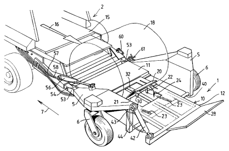
Fig. 1 shows in perspective a view of a bale collector 1
which is connected behind a baler 2. The bale collector 1
comprises a frame 5, to which two swivelling wheels 6 are
fixed. During operation the bale collector 1 is pulled along
by the baler 2 in a travel direction 7. A bearing platform
10, comprising a front part 11 and a rear part 12, is fitted
on the frame 5 between the two swivelling wheels 6. By way of
an outlet 15 thereof, the baler 2 delivers backwards in a
direction 16 and onto the bearing platform 10 a disc-shaped
round bale 18, an axis of which runs parallel to the ground
and crosswise to the travel direction 7. The rear bearing
part 12 has upwardly projecting non-return flap 20 which is
rotatable
CA 02288051 1999-10-26
WO 98/49885 PCT/NL98/00182
- 3 -
about a shaft 21 which has downwardly projecting arms 22.
Tension springs 23 are fixed between the ends of the arms
22 and the frame 5.
When the baler 2 ejects a bale 18 in the direction
16, the bale 18 will roll in succession onto the front
. bearing part 11 and against the non-return flap 20, with
the result that the non-return flap 20 rotates against the
action of the springs 23 in the direction of the arrow 24,
so that the bale 18 rolls over the flap 20 and behind it.
Further rolling of the bale 18 is prevented by a retaining
panel 28.
The non-return flap 20 is fitted on a construction
with a tubular piece 30 which is slidable parallel to the
travel direction 7 over a suitable pipe 32 of the rear
bearing part 12. The construction for the flap 20 can be
slid into and fixed in such a position that, after a bale
18 has passed the flap 20 towards the rear, the flap 20 can
rotate upwards again, as indicated by an arrow 35 in Fig.
2, and the bale 18 is subsequently retained between the
flap 20 and the retaining panel 28.
The rear bearing part 12 is rotatable about a shaft
40 which is parallel to the ground and crosswise to the
travel direction 7 and is fitted between the flap 20 and
the retaining panel 28.
The rear bearing part 12 is held in a horizontal
bearing position by a cylinder 42 mounted between the frame
5 and the rear bearing part 12. The cylinder 42 is fed by
way of lines 43, 44 from a tractor (not shown) connected in
front of the baler.
When a bale 18 is situated on the rear bearing part
12, and the bale collector 1 is situated at a desired point
on the land, the driver of the baler 2 operates the
cylinder 42, which causes the rear bearing part 12 to
rotate in the direction of the arrow 45, i.e. with the
retaining panel 28 towards the ground, as shown in Fig. 3.
The bale 18 consequently rolls off the rear bearing part 12
according to the arrow 46 over the retaining panel 28 and
onto the ground. The driver then operates the cylinder 42,
in order to rotate the rear bearing part 12 back to its
CA 02288051 1999-10-26
WO 98/49885 PCT/NL98/00182
- 4 -
previous position.
The bale collector acts as a buffer for a bale 18,
which can be deposited on the land at a desired point of
the travel route so long as the baler 2 is not ejecting the
next bale. If the bale collector 1 deposits a bale 18 on
the ground when the baler 2 has the next bale half ready,
the result is that for the point for depositing the next
bale a margin of more or less half the distance at which
the bales would be deposited on the ground directly from
the baler 2 is obtained. On the other hand, if the
depositing of a bale on the ground is delayed until the
baler 2 is almost ready with the next bale, and if these
two bales are then deposited on the ground shortly after
one another, pairs of bales situated at twice the above
distance from each other can be deposited on the ground. By
using the bale collector 1 according to the invention, the
bales 18 can therefore be deposited accurately at desired
points, for example in such a way that neat rows of bales
18 can be deposited on the land both parallel to the travel
direction 7 of the baler 2 and crosswise thereto. This
facilitates loading of the bales 18 deposited on the land
onto a transport vehicle.
Other advantages of the bale collector 1 according
to the invention are that the collector 1 is compact,
simple and cheap.
. The advantage of the compactness, with a short
length parallel to the travel direction 7, makes it
possible for the bale collector 1, as shown in Fig. 4, to
be transported on the back of the baler 2 in an upward
swung position according to an arrow 50 opposite the outlet
15 of the baler 2 shut off by a cap 51. This makes
transportation of the combination of the bale collector 1
and the baler 2 easier and safer both on the land and on
the public highway.
In order to reach the position of the bale
collector 1 shown in Fig. 4, the collector 1 and the baler
2 have two fork couplings 53, each with a shaft 54 whose
axes coincide. A cylinder 56, which is fed by way of lines
57, 58 from the abovementioned tractor (not shown?, is
CA 02288051 1999-10-26
WO 98/49885 PCT/NL98/00182
- 5 -
fitted between the bale collector 1 and the baler 2. When
the cylinder 56 is extended, the bale collector 1 is in a
working position as shown in Figs. 1, 2 and 3, and in a
retracted position of the cylinder 56 the idle position of
the bale collector 1 shown in Fig. 4 is obtained. The idle
position can be locked by means of locking means 60, 61.
Various modifications are possible for an expert
within the scope of the invention.
For example, the bearing platform 10 can consist of
a tubular construction without cover plate.
Instead of the tension springs 23, one or more
compression springs can be fitted between the frame 5 and
the flap 20. Moreover, instead of the springs 23, a
counterweight can be fitted on the ends of the arms 22, for
example a pipe filled with a heavy material and running
parallel to the ground.
Furthermore, the slide construction 30, 32 with the
non-return flap 20 can be fitted on the frame 5 in a
location such as that shown in Figs. 1 and 2, instead of on
the rear bearing part 12. The last-mentioned and
illustrated embodiment has the advantage that when the rear
bearing part 12 tilts according to the arrow 45 in Fig. 3
it is better ensured that a bale 18 rolls off the rear
bearing part 12 onto the ground, for example when the
combination of baler 2 and bale collector 1 is travelling
down a slope.
In addition, the construction with the non-return
flap 20 can be replaced or supplemented by non-return means
which act upon the side edges of a passing bale 18. For
this purpose, such a construction as the construction shown
can be used, but in which the axis of rotation is vertical.
Furthermore, for the cylinders 42 and 56 other
means can be used to rotate the rear bearing part 12
relative to the frame 5 or the frame 5 relative to the
baler 2. Even fully hand-operated means can be used.
Alternatively, instead of the cylinder 42, it is possible
to fit a locking mechanism of which parts are fitted on the
frame 5 or the bearing part 12, the mechanism being self-
locking when the bearing part 12 is rotated into the
CA 02288051 1999-10-26
WO 98/49885 PCT/NL98/00182
- 6 -
highest position of the rear part thereof, which can be
achieved by a suitable position of the centre of gravity of
the bearing part 12 under its own weight, while when the
operator unlocks the mechanism the bearing part 12 with a
bale 18 supported thereon rotates under its own weight to
the ground. The rotation back to the ground can be promoted
by using a tension spring fitted between the frame 5 and
the bearing part 12.
With a suitable length of the bearing part 12,
viewed in the travel direction 7, several constructions
with a non-return flap, such as the flap 20, can be fitted,
in which case a bale 18 can also be retained between two
adjacent non-return flaps 20. When the bearing part 12 is
rotated downwards, all bales 18 will roll off the bearing
part 12 onto the ground.
Although the bale collector 1 according to the
invention is explained for use behind a baler 2, the bale
collector can also be used for other types of bale delivery
devices, for example behind a wrapping device which wraps
each bale in a film and ejects film-wrapped bales through a
delivery opening to the bale collector 1.