Note: Descriptions are shown in the official language in which they were submitted.
CA 02288427 1999-11-19
PNEUMATIC PRESSURE OPERATED
PARKING BRAKE FOR A RAILWAY
VEHICLE BRAKE SYSTEM
This is a division of co-pending, commonly owned
Canadian Patent Application No. 2,188,107 filed October 17, 1996.
FIELb OF THE INVENTION
The present invention relates, in general, to various
types of railway vehicle braking systems and, more
particularly, the invention relates to an improved brake
system for a railway type freight car and, still more
particularly, the instant invention relates to a brake system
having an improved parking brake type system for use on such
railway type freight cars incorporated therein which
possesses the capability of utilizing a combination of
pneumatic and hydraulic pressure to enhance the performance
of such parking brake system.
BACKGROUND OF THE INVENTION
Frior to the conception and subsequent development of
the invention to be taught hereinafter, as is generally
quite well known in the railroad industry, railway type
freight cars are required to be equipped with a parking brake
as a part of the necessary braking system disposed on such
freight cars.
These prior art type parking brakes have to be set
manually. As a result, these parking brakes are commonly
known in the industry as hand brakes. Such parking brakes
1
CA 02288427 1999-11-19
are set, at least, when the brake pipe air line disposed on
such freight cars is not connected for fluid communication
with the brake pipe air line which is a part of the air brake
system disposed on a train consist. This would necessarily
be the case, for example, when such freight car is either
waiting to be connected into such a train consist or when
such freight car has been removed from such a train consist.
The parking brakes being used in this application, for
many years prior to the present invention, have all required
that they be both manually applied and thereafter released by
railroad personnel. Such manual application and subsequent
release of these hand brakes has required these prior art
type parking brakes to be equipped either with a rotatable
hand wheel member or with a pump action type hand crank
member .
Normally, either through the rotation of such hand wheel
member, or by pumping on the hand crank member, the required
amount of brake force can be generated and applied to the
brake beam, and/or beams. Such brake beam carries the brake
shoes thereon which are brought into frictional engagement
with at least a portion of the tread surface of the
respective wheels disposed on the truck member portion of a
freight car during a brake application.
2
CA 02288427 1999-11-19
Such required braking force is applied to these brake
beams, and then to the brake shoes, through a chain that is
connected at a first end thereof to a chain drum disposed in
the hand brake secured to the freight car and then connected
at a second end thereof to the brake beams, carrying such
brake shoes, through a brake lever system. Such chain drum
being rotated thorough the manual operation of the hand wheel
member or hand crank. These prior art type parking brake
systems are quite well known in the railway braking art and,
therefore, a further more detailed description of them here
in order to fully appreciate the advantages gained by the
present invention is believed to be unnecessary.
It is further well known in the railway industry that
these parking brakes are a highly critical component with
respect to the safe operation of a freight car. Therefore,
it is critical that they be maintained in very good working
condition at all times.
Recently, the Association of American Railroads (AAR)
made a specific request, to all of the manufacturers of such
railway freight car parking brake systems, to submit to them
any new proposals they might generate for improving such
parking brake systems. Such request by the AAR was
instrumental in leading to the development of the present
invention.
SUMMARY OF THE INVENTION
The invention in accordance with the parent application
provides a reliable and improved pneumatic pressure
actuated and hydraulically applied railway freight car type
parking brake system. This parking brake system includes a
3
CA 02288427 1999-11-19
source o.f- pneumatic pressure disposed on such freight car.
Such source of such pneumatic pressure must: be capab).e of
supplying a predetermined volume of air pressure which is at
least sufficient to actuate such parking brake system into a
brake application position. A control valve means is
disposed in f7_uid communication with this source of pneumatic
pressure and is engageabl_e on such freight car in a position
to receive the air pressure from such source of_ pneumatic
pressure. This control_ valve initiates a cont.roll_ed
communication of air pressure within such parking brake
system. A pneumatic pressure to hydraulic pressure
intensifier means is disposed i_n fl.uid communication with -the
source of pneumatic pressure. The pneumatic pressure to
hydraulic pressure intensifier means is engageabl_e on such
freight car in a position to receive such air pressure from
the control valve means. Z'his air pressure i_s communicated
to such intensifier means at least closely adjacent a closed
first end of a first chamber disposed therein. 11 second
chamber disposed in the intensifier means is connected at an
open first end thereof with a r_adially opposed and partially
open second end of such first chamber. There i_s a
predetermined volume of hydraulic fluid disposed in such
second chamber adjacent a closed second end thereof. 'this
brake system also includes a force transmi_tti.ng cylinder
means disposed on a truck portion of. such freight car. Such
force transmitting cylinder means is connected i.n flu.id
communication with such second chamber of the intensifier
means for exerting a predetermined force on an at least one
brake beam carrying a pair of brake shoes thereon. These
4
CA 02288427 1999-11-19
brake shoes are brought into and maintained in frictional
engagement with a predetermined portion of a respective
surface of a tread portion of a pair of wheels during an
application of such parking brake. A piston member is
disposed for reciprocal movement within such first chamber of
the intensifier means. Such piston member being linearly
displaced when a first surface of such piston member,
disposed facing said closed first end of said first chamber,
is acted on by the air pressure being communicated to such
intensifier means during an application of such parking
brake. A first sealing means is disposed around a peripheral
portion of the piston member for containing the air pressure
being communicated to the intensifier means, during such
application of the parking brake, within that portion of the
first chamber located between such first surface of the
piston member and the closed first end of such first chamber.
A stem member is connected at a first end thereof to a
radially opposed second surface of such piston member. This
stem member is disposed for reciprocal movement within both
the first chamber and the second chamber. This stem member
is linearly displaced within both such first chamber and~such
second chamber by movement of the piston member. There is a
second sealing means disposed around a peripheral portion of
the stem member closely adjacent an axially opposed second
end thereof. This second sealing means retains the hydraulic
fluid disposed in such second chamber within that portion of
the second chamber located between the second end of such
stem member and the closed second end of such second chamber
thereby enabling communication of the hydraulic fluid to the
CA 02288427 1999-11-19
force transmitting cylinder means. This occurs by linear
displacement of such stem member whereby such predetermined
force. is exerted on such at least one brake beam carrying
such pair of brake shoes thereon which are brought into and
maintained in frictional engagement with a predetermined
portion of a respective surface of a tread portion of a pair
of wheels during an application of such parking brake.
On the other hand, the present invention provides a
hydraulically applied railway type freight car parking brake
system. According to this second embodiment such parking
brake system includes a source of hydraulic pressure disposed
on such freight car for supplying a predetermined fluid
pressure which is at least sufficient to actuate and
maintain said parking brake system in a brake application
position. There is a brake application means connected to
such source of hydraulic pressure for communicating such
hydraulic pressure to a force transmitting cylinder means
disposed on a truck portion of such freight car and connected
in fluid communication with such source of hydraulic
pressure. Such force transmitting cylinder means exerting a
predetermined force on an at least one brake beam carrying a
pair of brake shoes thereon which are brought into and
maintained in frictional engagement with a portion of a
respective surface of a tread portion of a pair of wheels
during an application of said parking brake.
OBJECTS OF THE INVENTION
It is, therefore, one of the primary objects of the
present invention to provide a pneumatic pressure operated
parking brake for a railway vehicle parking brake system
6
CA 02288427 1999-11-19
which does not require either a hand wheel member or a hand
crank member to be utilized in order to apply and/or release
such parking brake system.
Another object of the present invention is to provide a
pneumatic pressure operated parking brake for a railway
vehicle parking brake system which, in addition to being
effectively utilized in new railway vehicle type
construction, can be readily and easily retrofitted onto the
existing railway type freight cars to provide an enhanced
performance of such parking brake system.
Still another object of the present invention is to
provide a pneumatic pressure operated parking brake for a
railway vehicle parking brake system which can effectively
incorporate the use of both pneumatic and hydraulic pressure
therein.
Yet another object of the present invention is to
provide a pneumatic pressure operated parking brake for a
railway vehicle parking brake system which can be
specifically designed to be applied and/or released from
either side or both sides of such railway vehicle.
A further object of the present invention is to provide
a pneumatic pressure operated parking brake for a railway
vehicle parking brake system which can be easily adapted for
use with the numerous different style brake beams which are
being used to carry the brake shoes, at the present time, in
such railway vehicle type brake systems.
It is still an additional object of the present
invention to provide a pneumatic pressure operated parking
brake for a railway vehicle parking brake system which can be
7
CA 02288427 1999-11-19
applied with fluid pressure in a first direction and released
by a spring in an axially opposed second direction.
Another object of the present invention is to provide a
pneumatic pressure operated parking brake for a railway
vehicle parking brake system which may include at least one
fail safe type feature therein.
Still yet another object of the present invention is to
provide a pneumatic pressure operated parking brake for a
railway vehicle parking brake system which will not cause any
type detrimental interference with the required normal
operation of such railway vehicle's primary air brake system
when such parking brake system is not in use.
Yet still another object of the present invention is to
provide a pneumatic pressure operated parking brake for a
railway vehicle parking brake system which can be operated
from either the ground level, from the vehicle itself, or
from both the ground level and the vehicle itself.
It is a still further object of the present invention to
provide a pneumatic pressure operated parking brake for a
railway vehicle parking brake system which is relatively
simple to operate.
A further object of the present invention is to provide
a pneumatic pressure operated parking brake for a railway
vehicle parking brake system which is relatively simple to
install.
In addition to the several objects and advantages of the
present invention that have been discussed in some detail
above, various additional objects and advantages of the
pneumatic pressure operated parking brake for a railway
8
CA 02288427 1999-11-19
vehicle brake system, according to the present invention,
will become more readily apparent to those persons who are
skilled in the railway vehicle braking art from the following
more detailed description of the invention, particularly,
when such detailed description is taken in conjunction with
the attached drawing Figures and with the appended claims.
BRIEF DESCRIPTION OF THE DRAWINGS
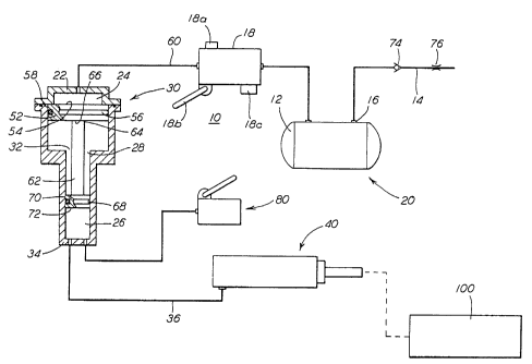
Figure 1 is a schematic illustration of a presently
preferred embodiment of a pneumatic pressure operated parking
brake for a railway vehicle brake system in accordance with
the present invention;
Figure 2 is a cross sectional view of a presently
preferred force transmitting cylinder means for use in such
pneumatic pressure operated parking brake for a railway
vehicle brake system; and
Figure 3 is a side view of a presently preferred
retraction means for use in a pneumatic pressure to hydraulic
pressure intensifier means produced according to the present
invention.
BRIEF DESCRIPTION OF THE PRESENTLY
PREFERRED AND VARIOUS ALTERNATIVE
EMBODIMENTS OF THE INVENTION
Prior to proceeding to the more detailed description of
the instant invention, it should be noted that, for the sake
of clarity and understanding of the invention, identical
components which have identical functions have been
identified with identical reference numerals throughout the
different views which are illustrated in each of the attached
drawing Figures.
9
CA 02288427 1999-11-19
Reference is now made, more particularly, to Figure 1 of
the attached drawings. Illustrated therein is a presently
preferred embodiment of the pneumatic pressure operated
parking brake system, generally designated 10, for a railway
vehicle brake system (not shown). More specifically, this
parking brake system 10 is a pneumatic pressure actuated and
hydraulically applied railway type freight car parking brake
system.
Such parking brake system 10 includes a source of
pneumatic pressure, generally designated 20, disposed on such
freight car (not shown) for supplying a predetermined volume
of air pressure. This predetermined volume of air pressure
must be at least sufficient to actuate the parking brake
system 10 into a brake application position.
In the presently preferred embodiment of the invention,
such source of pneumatic pressure 20 is an air reservoir 12.
The air reservoir 12 is connected to receive compressed air
from the brake pipe 14 disposed on such freight car at an
input side 16 thereof.
There is a control valve means 18 disposed in fluid
communication with the source of pneumatic pressure 20.
Control valve means 18 is engageable on and secured to such
freight car in a position to receive such air pressure from
the source of pneumatic pressure 20 for initiating
controlled communication of such air pressure in the parking
brake system 10.
Such control valve means 18 for use in the parking brake
system 10 of this invention can be one of an electrically
operated control valve, a manually operated control valve and
an electrically operated control valve equipped with a manual
backup capability.
CA 02288427 1999-11-19
In an embodiment of the invention where such control
valve means 18 is an electrically operated control valve, it
is presently preferred that such control valve means 18
includes a push button means 18a for initiating the operation
of such control valve means 18.
On the ether hand, when such control valve means 18 is a
manually operated control valve, the presently preferred
means of initiating the operation of such control valve means
18 is a lever type mechanism 18b.
In certain applications of such parking brake system 10,
according to the invention, such control valve means 18 can
be an electrically operated type control valve means 18
having a manual override means 18c for initiating the
operation of such parking brake system 10 in the event of a
power loss on such freight car.
According to the present invention, such parking brake
system 10 includes a pneumatic pressure to hydraulic pressure
intensifier means, generally designated 30. Such intensifier
means 30 is disposed in fluid communication with the source
of such pneumatic pressure 20 and is engageable on and
secured to such freight car in a position for receiving air
pressure from such control valve means 18. Such air pressure
is communicated to such intensifier means 30 closely adjacent
the closed first end 22 of a first chamber 24 disposed within
such intensifier means 30.
A second chamber 26 is disposed within such intensifier
means 30. This second chamber 26 is connected at an open
first end 28 thereof to communicate with a radially opposed
and partially open second end 32 of such first chamber 24.
There is a predetermined volume of hydraulic fluid disposed
11
CA 02288427 1999-11-19
in such second chamber 26 adjacent a closed second end 34
thereof.
According to the presently preferred embodiment of the
invention, such first chamber 24 and such second chamber 26
will exhibit an elongated cylindrical shape. A diameter of
such first chamber 24 is substantially larger than the
diameter of such second chamber 26.
The parking brake system 10 includes a force
transmitting cylinder means, generally designated 40. Such
force transmitting cylinder means 40 is disposed on a truck
portion (not shown) of such freight car and is connected in
fluid communication, via line 36, with such second chamber 26
of the intensifier means 30. The force transmitting cylinder
means 40 exerts a predetermined force on an at least one
brake beam carrying a pair of brake shoes thereon which are
brought into and maintained in frictional engagement with at
least a portion of a respective surface of a tread portion of
a pair of wheels during an application of the parking brake
system 10. As the structure and interrelationship of brake
beams, brake shoes, railcar wheels and their tread portions
are well known in the railroad industry, these features,are
represented graphically in Figure 1 as mechanical linkage
100.
In the presently preferred embodiment of the parking
brake system 10, as best seen in Figure 2, such force
transmitting cylinder means 40 will include a locking means,
generally designated 50, for holding a brake force in such
parking brake system 10 in the undesirable event of the
hydraulic pressure bleeding off.
12
CA 02288427 1999-11-19
Such locking means 50 is formed by a first clutch
surface 38 carried by the housing member 42 and a second
clutch surface 44 carried by a threaded nut member 46
threadedly engaged with a threaded rod-like member 48. By
virtue of the fact that such threaded nut member 46 causes
the threaded rod-like member 48 to be extended out of such
force transmitting cylinder means 40 such locking means 50
will enable adjusting for any slack which may be present in
such parking brake system 10. As is well known in the
railway braking art, such slack results from a number of
reasons. Such reasons, for example, will at least include
frictional wear of the brake shoes and of the various
linkages in the freight car brake system.
A piston member 52 is disposed for reciprocal movement
within such first chamber 24 of the intensifier means 30.
Such piston member 52 is positioned such that it will be
linearly displaced when a first surface 54 of the piston
member 52 is acted on by the air pressure that is being
communicated to such intensifier means 30 during an
application of such parking brake system 10. The first
surface 54 of such piston member 52 is disposed facing such
closed first end 22 of the first chamber 24.
There is a first sealing means 56, such as an O-ring,
disposed around a peripheral portion 58 of such piston member
52. The first sealing means 56 ensures that the air pressure
being communicated to such intensifier means 30, via line 60,
during an application of the parking brake system 10 is
contained within that portion of the first chamber 24 located
13
CA 02288427 1999-11-19
between such first surface 54 of the piston member 52 and
such closed first end 22 of the first chamber 24.
A stem member 62 is connected at a first end 64 thereof
to a radially opposed second surface 66 of such piston member
52. The stem member 62 is disposed for reciprocal movement
within both the first chamber 24 and the second chamber 26.
As is evident such stem member 62 will be linearly displaced
within both such first chamber 24 and such second chamber 26
by the movement of such piston member 52.
The final essential component of the parking brake
system 10 is a second sealing means 68, such as an O-ring.
Such second sealing means 68 is disposed around a peripheral
portion 70 of such stem member 62. closely adjacent an axially
opposed second end 72 thereof. This second sealing means 68
ensures retention o~ such hydraulic fluid disposed in such
second chamber 26 within that portion of the second chamber
26 located between such second end 72 of the stem member 62
and such closed second end 54 of the second chamber 26
thereby enabling communication of such hydraulic fluid, via
the line 36, to such force transmitting cylinder means 40.
Such communication of the hydraulic fluid occurring by the
linear displacement of such stem member 62. This hydraulic
fluid, communicated to the force transmitting cylinder means
40, causes such predetermined force to be exerted on such at
least one brake beam carrying such pair of brake shoes
thereon which are brought into and maintained in frictional
engagement with a portion of a respective surface of a tread
portion of a pair of wheels during an application of such
parking brake system 10.
14
CA 02288427 1999-11-19
The pneumatic pressure actuated and hydraulically
applied railway freight car parking brake system 10,
according to a presently preferred embodiment of the
invention, will further include a one way check valve means
74 disposed in brake pipe 14. Such check valve means 74 will
permit the compressed air to be communicated to the air
reservoir 12 and will further prevent such compressed air
from returning to such brake pipe 14 from such air
reservoir 12.
Additionally, in this presently preferred embodiment,
such parking brake system 10 will further include a choke
means 76. Such choke means 76 is disposed in such brake pipe
14 ahead of such check valve means 74. Choke means 76
provides a preferred way of controlling the flow of such
compressed air to such air reservoir 12 in a relatively slow
charge manner.
AJ_so, it is presently preferred that such pneumatic
pressure actuated and hydraulically applied railway freight
car parking brake system 10 will further include an auxiliary
type brake application means, generally designated 80. Such
auxiliary type brake application means 80 is connected to
such second chamber 26 in the intensifier means 30 closely
adjacent the closed second end 34 thereof. This auxiliary
type brake application means 80 will enable the application
of such parking brake system 10 to occur even in the event
there is an undesirable absence of air pressure in such
source of pneumatic pressure 20, or such air reservoir 12.
In the most simple form, such auxiliary type brake
application means 80 can be a fluid pressure type pump. Such
CA 02288427 1999-11-19
fluid pressure type pump may be, for example, an electric
motor driven pump (not shown), a manually operated type pump
or a pump that is designed to have the capability of being
operated both electrically and manually. In the presently
preferred embodiment of the invention, such fluid pressure
type pump is a manually operated type hand pump.
In the pneumatic pressure actuated and hydraulically
applied railway freight car parking brake system 10,
according to the presently preferred embodiment of the
invention, such pneumatic pressure to hydraulic pressure
intensifier means 30 will further include a retraction means,
generally designated 90. Such retraction means 90 is
disposed in one of such first chamber 24 and such second
chamber 26 in a position to enhance retraction of the piston
member 52 and such stem member 62 toward the closed first end
22 of such first chamber 24 located in such intensifier means
30 upon the release of such parking brake system 10.
According to the presently preferred embodiment of the
instant invention, such retraction means 90 will include at
least one of a spring member 78, caged between the second.
surface 66 of such piston member 52 and such partially open
second end 32 of the first chamber 24 disposed in such
intensifier means 30, and a spring member 82, caged between
such second end 72 of the stem member 62 and such closed
second end 34 of the second chamber 26, in order to assist in
the retraction of such piston member 52 toward such closed
first end 22 of such first chamber 24 in the intensifier
means 30 upon the release of such parking brake system 10.
In the most preferred embodiment, such retraction means 90 is
16
CA 02288427 1999-11-19
the spring member 78 caged between such second surface 66 of
such piston member 52 and the partially open second end 32 of
such first chamber 24 disposed in such intensifier means 30.
In a second embodiment of the present invention, there
is provided a hydraulically applied railway type freight car
parking brake system. This parking brake system includes a
source of hydraulic pressure disposed on such freight car for
supplying a predetermined fluid pressure which is at least
sufficient to actuate and maintain such parking brake system
in a brake application position.
Such source of fluid pressure may be, for example, the
hydraulic fluid that is disposed in the second chamber 26 of
the intensifier means 30, and/or a separate reservoir (not
shown) for containing therein a predetermined volume of such
hydraulic fluid.
A brake application means, such as the auxiliary brake
application means 80 discussed above with respect to the
first embodiment is provided. This brake application means
is connected to such source of hydraulic pressure for
communicating such hydraulic fluid.
In the most simple form, such auxiliary type brake
application means 80 can be a fluid pressure type pump. Such
fluid pressure type pump may be, for example, an electric
motor driven pump (not shown), a manually operated type pump
or a pump that is designed to have the capability of being
operated both electrically and manually. In the presently
preferred embodiment of the invention, such fluid pressure
type pump is a manually operated type hand pump.
17
CA 02288427 1999-11-19
Like the first embodiment of the invention, there is a
force transmitting cylinder means 40 disposed on the truck
portion of such freight car which is connected in fluid
communication with such source of hydraulic pressure for
exerting a predetermined force on an at least one brake beam
carrying a pair of brake shoes thereon which are brought into
and maintained in frictional engagement with a portion of a
respective surface of a tread portion of a pair of wheels
during an application of said parking brake.
In the presently preferred alternative embodiment of the
parking brake system, as best seen in Figure 2, such force
transmitting cylinder means 40 will include a locking means,
generally designated 50, for holding a brake force in such
parking brake system 10 in the undesirable event of the
hydraulic pressure bleeding off.
Such locking means 50 is formed by a first clutch
surface 38 carried by the housing member 42 and a second
clutch surface 44 carried by a threaded nut member 46
threadedly engaged with a threaded rod-like member 48. Hy
virtue of the fact that such threaded nut member 46 causes
the threaded rod-like member 48 to be extended out of such
force transmitting cylinder means 40 such locking means 50
will enable adjusting for any slack which may be present in
such parking brake system. As is well known in the railway
braking art, such slack results from a number of reasons.
Such reasons, for example, will at least include frictional
wear of the brake shoes and of the various linkages in the
freight car brake system.
18
CA 02288427 1999-11-19
Finally, it is within the spirit of the present
invention and the scope of the claims directed thereto for
such force transmitting cylinder means 40 to be a simple
hydraulic type cylinder.
While a presently preferred and a number of alternative
embodiments of the present invention have been described in
detail above, it should be understood that various additional
adaptations and/or modifications to such invention can be
made, particularly, by those persons who are skilled in the
railway vehicle type braking systems art without departing
from either the spirit of the instant invention or the scope
of the appended claims.
19