Note: Descriptions are shown in the official language in which they were submitted.
, CA 02288749 1999-11-O1
Mobile radio with reduced key set
The present invention relates t:o a method and a
system for mobile radio transmission by means of a
mobile unit.
In mobile radio telephones (mobile phones) the
size and the weight of the mobile phone is a decisive
factor for the user. This means that if a mobile phone
is~ smaller and lighter in weight, it can be carried
more conveniently by the user and be available at all
times_ Meanwhile, the process of reducing the size of
conventional mobile phones has reached a limit which it
seems virtually impossible to overcome. The length of a
mobile phone in the operational state is defined by the
distance between the user ~ s mouth and one of his ears .
For this reason, when the mobile phone is in the state
in which it is not ready to be spoken into its length
can be reduced further by, for example, folding it up.
Therefore, it has become apparent that the
keypad is a decisive factor, in particular for the _
width dimension of a mobile phone. U.ually, a mobile
phone has the ten immediately required dialling keys
together with a number of further key: for additional
functions so that as a rule approximately 20 keys are
arranged on a keypad on the upper side of a mobile
phone. Technically it is possible to implement an
overall further reduction in the number of keys of the
keypad in order to reduce the size of the mobile phone,
but there axe natural limits to the reduction in size
in that it must be possible for a finger of a hand of
an adult to be able to activate a key reliably and
clearly. This means that the distance between two keys
must be at least such that when a key is activated an
adjacent key is not undesirably activated also under
circumstances. Bven if, in order to reduce the size of
the keypad, most additional function keys are omitted,
at least the ten keys which are necessary for dialling
a number together with an on/off switch are left. There
CA 02288749 1999-11-O1 w-------.-..-.._
- la -
is also the problem that in particular the reduction of
the width of conventional mobile phones has reached a
limit.
EP-A-0 S54 625 discloses a mobile radio system
in which connection destinations are assigned in the
base station of the system and said connection
destination assignments are stored in said base
station.
GB-A-2 305 577 discloses a method in which a
mobile unit is firstly connected to a base station and
then connection destinations are assigned to
destination dialling keys.
EP-A-0 524 652 discloses how a mobile phone is
physically connected to a programming device in order
to transmit key assignments which are F~rogrammed on the
programming device to direct dialling keys of the
mobile radio unit vi.a an interface.
US-A-4 969 180 discloses a pin into which a
mobile phone is integrated. Communication is possible
here only with a predefined base stat~.on.
Patent Abstracts of Japan, Vol. 03.7, No. 287
(E-1374), 2 June 1993 and JP-A-05 014461 discloses a
wireless telephone system.
CA 02288749 1999-11-O1
S The object of the present invention is
therefore to design a mobile radio transmission system
in such a way that a particularly comt~act design of the
associated mobile phone is made possible.
The invention is based on the idea that the key
set can be severely reduced and the operational
capability of the mobile phone is nevertheless
completely ensured if access to specific functions of
the mobile unit are exported, for example, into an
intelligent switching service.
I5 The invention therefore provides a method for
configuring a mobiles unit, the mobile unit having one
or more dialling keys. All of the dialling keys are
each assigned one connection destination. By activating
a dialling key it is thus possi;~le to connect
ZO exclusively to the assigned connection destination. The
assignment to a central key is made he=a in such a way
that the user of the mobile unit cannot change it
directly by accessing the mobile unit.
This means that according to the invention the
25 mobile unit does not have any keys which serve in the
conventional sense for exclusively inputting a digit
but rather that the mobile unit has only connection
set-up- keys which permit a connection set-up to a pre
programmed connection destination by means of a single
30 activation (direct dialling keys). B_~ activating a
central key of the mobile unit a conne<:tion is set up
from the mobile unit to a central switching device, for
example.
A password table which contains subscriber data
35 with a respectively assigned password can be stored in
the central switching device. After the set-up of the
connection from the mobile unit to the central
switching device, subscriber data and a password a-re
then transferred Lrom the mobile unit to the central
CA 02288749 1999-11-O1
- 3 -
switching device. The central. swite:zing device then
~, compares the transferred subscriber data and/or the
transferred password with the data stored in the
password table. In the event that this comparison
results in a correspondence between the transferred
subscriber data and the transferred ~,assword with the
corresponding data in the password table, the central
switching device then forwards the c~~nnection of the
user of the mobile unit as desired. Since,~according to
the invention, it is not necessary to key in a code to
activate the mobile unit, the user's security, for
example in the event of a theft or other loss of the
mobile unit, is ensured by the passwor3 which is to be
transferred to the central switching device.
The assignment of a connection destination to
in each case one of the connection sEa-up keys, with
the exception of the central key, can. be carried out
here by means of a data transfer from the central
switching centre to the mobile unit. It should be noted
here that owing to the reduced key seC:, i.e. owing to
the fact that only the aforesaid direct dialling keys
are provided on the mobile unit, programming
(assignment) of a connection destination to one of the
connection set-up keys cannot be carried out at the
mobile unit by the user himself.
As an alternative, or in addition, for the
assignment of a connection destination to in each case -
one of the connection set-up keys, with the exception
of the central key, the mobile unit can be inserted
into a base station, the assignment thE:n being carried
out by means of a data transmission from the base
station to the mobile station.
The base station can simultaneously serve as a
charger station. This means that when the mobile unit
is inserted into the base station.an accumulator in the
mobile unit can be charged at the same time.
zn the password table of the central switching
device, a list of preferred connection destinations can
be assigned in each case to a password and/or to
CA 02288749 1999-11-O1
- 4 -
respective specific subscriber data. Z'he function of a
personal telephone directory is thus made possible.
A particularly simple method of operation is
obtained if the activation of the central. key firstly
switches on the mobile unit, a further activation of
the central key then sets up the connection to the
central switching device, yet another asctivation of the
central key releases the connection to the central
switching device and a further activation of the
1,0 central key then switches the mabile unit off again.
The mobile unit can preferably have a key lock,
preventing the mobile unit from being switched on
unintentionally. The key lock can b~~ overcome, for
example, by a coc:~bination of a plurali~~y of keys or by
pressing a key for a predefined period ~~f time.
One of the connection set-up keys can be
assigned an emergency-call connection destination. By
pressing once on this emergency-call k~ay, a connection
can thus easily be set up to an emergency-call
organization, which is advantageous in particular for
people for whom it is not possible to compose a
complete number using conventional dialling keys
because of physical and/or mental disab:.lities.
,According to a further aspect of the invention,
a mobile radio transmission system is provided with at
least one mobile unit and one central switching centre.
For performing connection set-ups, the mobile unit here
has merely one or more keys, which, by being activated
once, can set up a connection, zn the manner of a
direct dialling operation, to a cannection destination
which is assigned to the respective key. A central key
to which a central switching device is assigned as a
permanently pre-programmed connection destination is
provided here. Permanently pre-programmed is intended.
to mean here that it is not possible, ~a least for the
user of the mobile unit, to assign to the central key
any connection destination other th~;n the central
switching device.
...... .__..,,..,; .:... .;:.:,:..
CA 02288749 1999-11-O1
The central switching device can have a
- ~ password table which contains subscriber data with a
respectively assigned password. It is possible to
provide a device by means of which, after the set-up of
5 the connection from the mobile unit to the central
switching device, subscriber data and a password can be
transferred tv the central switching device. A device
for comparing the transferred subscriber data and/or
the transferred password with the password table is
then provided in the central switching cievice.
In the event that the call transfer by the
central switching device does not take place, because,
for example, the desired subscribe:. is currently
engaged, a redial function may be provided in the
mobile unit, for example by means of t:he central key,
so that by simply activating the ce~~ztral key again
without cooperation a renewed dialling attempt can be
carried out.
In the central. switching device, it is also
possible to provide a device for assigning a connection
destination to in each case one of the connection
set-up keys, with the exception of the central key, the
assignment being effected by means of a data transfer
from the central switching centre to the: mobile unit.
The mobile radio transmission system can be
provided with a base station into which the mobile unit
can be inserted in order to carry out an assignment -
(programming) of in each case one connection
destination to one of the connection sEa-up keys, with
the exception of the central key, by means of a data
transfer from the fixed station to the mobile unit.
The base station can simultaneously be a
charger station which, when the mobile unit is in the
inserted state, charges an accumulator in said mobile
unit. The base station can have all the functions of a
conventional telephone end in particular a hands-free
talking facility.
A list of preferred connection destinations,
which is assigned to a password andjor to specific
..~s ;-, , . . ~v,~.~!)i7:7:<;'n';v.
CA 02288749 1999-11-O1
- - 6 -
subscriber data, may be provided in the password table
_ ; of the central switching device.
The invention will now be e~:plained in more
detail by means of exemplary embodiments and with
reference to the accompanying drawings, in which:
Fig. 1 shows a first exemplary embodiment of a
mobile unit as is used in the present invention
in accordance with a first exemplary
IO embodiment,
Fig. 2 shows a further mobile ~~nit, as is used
in the present invention in accordance with a
further exemplary embodiment,
Fig. 3 shows a mobile unit in the state in
which it is inserted into a base station in
accordance with the invention,
Fig. 4 shows an internal design of a mobile
unit in accordance with the pr~asent invention,
and
Fig. 5 shows a schematic view of a system
according to the invention for mobile radio
transmission.
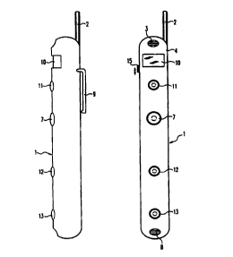
Fig. 1 shows a mobile unit z as is used in the present
invention. The mobile unit 1 has here an antenna 2, a
casing 4, a loudspeaker 3 and a microphone 8. The
distance between the loudspeaker 3 and the microphone 8
corresponds essentially to the distar..ce between the
mouth of an adult and one of his ears. The length of
the mobile unit 1 is determined essentially by the
distance between the loudspeaker 3 and the microphone
8. The width of the mobile unit 1 which is illustrated
in Fig. 1 is, for example, 2 to 3 cm. 'this small width
of the mobile unit 1 is, as is clear, made possible by
the fact that a conventional keypad comprising a
~
CA 02288749 1999-11-O1
_ 7 _
plurality of keys, each for inputting one digit, is not
_ ,
provided on the surface of the mobile unit 7., i.e, on
the casing 4 of the mobile unit 1. Tt~e mobile unit 1
according to the exemplary embodiment. illustrated in
Fig. 1 has just one key, namely a central key 7. If
this central key 7 is pressed once, the mobile unit 1
is switched on. Directly after operation, after
successful authorization checking of t:he inserted SzM
card there is immediately the search for an accessible
mobile radio network. The flashing of a network diode 5
shows here that the search process is being carried
out. When the network diode 5 lights u~~ uninterruptedly
this indicates that a network connection has been
successfully found. After this process of searching for
and signing onto a mobile radio network, the mobile
unit I is then in a state zn which it can be dialled up
in the same way as a conventional mobile phone. zt is
not necessary to input a so-called PIN code manually in
order to activate the mobile unit 1 be~ause, as stated
2o above, internal checking of the authorization is
carried out automatically.
The network diode S can also have the function
that a change in the colour of its li~~ht, far example
from green to red, indicates the status in which a
connection has been set up.
The mobile unit 1 also has a volume controller
for the loudspeaker . 3, which is however not
illustrated.
In the switched-on state of thE: mobile unit 1,
calls can thus be received. These calls may be
signalled audibly, visually or by vi:oration. In the
exemplary embodiment illustrated in Fig. 1, a call is
represented by means of an LED 5. This call LED 5
flashes when a call is received, and lights up
continuously while a call is being made. By pressing
the central key 7 it is possible to terminate again an
ongoing call. when the call is terminated, the call
LED 5 thus goes out.
.. . , . . ... . . ,.~ . . .. ,, . , ,. ,~ .. ., , . .~,,~ . . ~....
CA 02288749 1999-11-O1
. _ g _
. ; An explanation of how outgoing calls can be
made from the mobile unit 1 will now be given below.
The condition for this is firstly that: the mobile unit
1 has been switched on and the network LED 6 is lit up,
that is to say there is a connection t:o a mobile radio
network. By pressing the central key 7 once more, a
connection can then be set up to a connection
destination, the predefined connection destination
being permanently programmed into the mobile unit 1,
IO for example by the network operator, the manufacturer
of the mobile phone unit or the operator of the
connection destination. "permanently programmed" means
in the terms of the present invention: that simply by
accessing the mobile phone unit 1 it is. not possible to
change or delete the predefined connection destination
which is assigned to the central key 7 by permanent
pre-programming. The programming of the connection
destination which. is assigned to the <:entral key 7 is
therefore not carried out by the user of the mobile
2o unit 1 but is instead provided on a one-off basis by
the manufacturer before the mobile unit z is sold. A
possible predefined connection destir.:ation wh~.ch is
assigned to the central key 7 by pre-programming would
be, in particular but not necessarily, a central
switching device. The precise operation of the central
switching device is described below. Pressing the
central key 7 a second time thus sets up a direct
cannection to the central switching device which can
then connect the user of the mobile unit 1 to any
3o desired further subscriber, as is also ~:et out below.
The exemplary embodiment of a mobile unit 1
which is illustrated in Fig. 1 is thus dimensioned, by
omitting a keypad and replacing the keypad with a
single dialling key in the form of the central key 7,
in such a way that it can be worn or carried in a
desired way, for example by means of a clip 9 or can be
hung around the neck on a cord (not illustrated), so
that, for example, a fitter can work raith both hands
and at the same time be instructed online by the mobile
TOTAL P.09
CA 02288749 1999-11-O1
_ g _
unit 1 which is hung around his neck and switched on.
For thzs purpose, it is possible preferably to provide
a known earpiece since the fitter cannot of course hold
the mobile unit 1 against his ear while working.
A further embodiment of a mobile unit 1
according to the invention will now bE~ explained with
reference to Fig. 2. The mobile unit 1 which is
illustrated in Fig. 2 has all the Elements of the
mobile unit 1 illustrated in Fig. 1. The mobile unit 1
illustrated in Fig. 2 differs essentially from the
mobile unit illustrated in Fig. 1, in that a plurality
of direct connection keys 7, 11, 12, 7.3 are provided.
Furthermore, in the exemplary ernbodimen~= in Fig. 2, the
on/off switching function for the mobile unit 1 is
provided separately tram the central key ~, namely in
the form of an or_/off switch 1S. This on/off switch of
the mobile unit 1 according to Fig. 2 i;s located on the
side of the casing 4 of the mobile unit 1 and can be
pushed up or down to switch the mobi_e phone on and
off. In addition:, the mobile unit il~us~trated in Fig. 2
has a display panel 10.
The function of the other direct connection
keys 7.1., ~,2, 7.3 of the mobile unit 1 in Fig. 2 will now
be explained. These direct connection keys 11, 12, 13
have in common with the central key 7 t:he fact that by
means of a single activation they can set up a
connection to a connection destination which is _
respectively assigned to them. For example, the key 13
can be assigned, as connection destination, an
emergency-call destination, i.e. an emergency-call
organization. The keys 11 and 12 can be freely assigned
as direct connection keys, for example for frequently
desired connections, by the user of the: mobile unit 1,
as will be described below.
3S Even though it is not illustrated, the mobile
unit 1 in Fig. 2 can also have an interface which
permits connection to a known GSM modem.
The keys which can be freely assigned by the
user can be assigned as follows. Firstl~r, the user sets
;~.~fo ~. . ; . .. ,... . ,; . ,
CA 02288749 1999-11-O1
' - 10 -
up a connection to the central swit~~hing device by
activating the central key 7. As soon as he has a
connection to the central switching device, the user
of the mobile unit 1 transfers information, namely
specifying which connection destination is to be
assigned to which of the freely assignable keys 11 to
12, to the central switching device. This information
can be 'voice information. The acaual assignment
(programming? of the freely assignable: keys 11, 12 is
then not carried out directly on the mobile unit 1
itself but rather, for example, by means of known DTMF
instructions from the central switchi~zg device to the
mobile unit 1 via a radio transmission path. The
assignment of the freely assignable keys 11, 12
therefore does not take place in each ease locally at a
mobile unit 1 but instead occurs as a central facility
of the switching device.
Before the actual storage of the transmitted
assignment, the data which are transmitted from the
central switching device 3o are displayed on the
display 10 of the mobile unit 1. The ultimate storage _
of the assignment takes place only after this, as a
result of the user pressing a key; fo:r example one of
the dialling keys 7, 11, 12, 13.
Call number memories, which are assigned to
individual keys, and memory locations of a telephone
directory on the SIM card can be .assigned- by the
central switching device 30. In addition, in response
to an appropriate call from the mobile unit 1 to the
central switching device 30, the central switching
device 30 can transmit to the mobile unit 1 information
which defines the type of call tone or call tones which
will be heard when the mobile unit 1 is used-
Furthermore, other features of the mobile unit 1, such
as call lock-out, call divert, deaci_ivation of the
greeting text and modification/selection of icons for
the memory locations of the call number memories of the
direct dialling keys can be brought about in response
to a call from the mobile unit 1 to the central
' CA 02288749 1999-11-O1
11
switching device 30 by transmitting appropriate
information from the central switching device 30 to the
mobile unit 1.
A further possible way of programming the
freely assignable keys 11, 12 is zllus~trated in Fig. 3.
Fig. 3 illustrates the mobile unit 1 in the state in
which it is inserted into a base station 20. In. the
inserted state it is electrically connected to the base
station 20 in such a way that an accumulator 14 which
7.0 ensures that the mobile unit 1 is supp:Lied with voltage
is charged from the base station 20. The base station
20 thus also serves as a charger station for the
accumulator 14 of the mobile unit 1. As is clear in
Fig. 3, the base station 20 has all the control
elements which are customary in a conventional
telephone, namely a complete control keypad 23 with at
least 10 control keys and a large-format LCD display
21. Furthermore, the base station 20 illustrated in
Fig. 3 has a central key 22 which p~arforms the same
function as the central key 7 of th~~ mobile unit 1
which is e:cplained above when the mabil a unit 1 ~ is
inserted into the base station ,~:0. As already
explained, the ar_cumulator 14 of the mobile unit I is
charged in the state in which the mobile unit I is
inserted ~.nto the base station 20. Furthermore, the
control pad 23 of the base station 20 makes it possible
to carry out the assignment of the freely assignable
keys 11, 12 of the mobile unit 1. This means that
assignment data which respectively assign connection
destinations to the individual freely assignable keys
I1, 12 are transmitted from the base station 20 to the
mobile unit 1. As already stated, the assignment of the
connection destination for the central key 7. cannot be.~
changed by means of the base station 20 either.
The internal design of a rnobile> unit 1 will now
be e:cplained with reference to Fig. 4. The central
component of the electronic system in a mobile unit 2
is, as illustrated, a processor 40 which may be, for
example, a commercially available ~~hip for mobile
phones. Voice data, which are made available by means
CA 02288749 1999-11-O1
- 12 -
of a digitization, using an A/D converter 46, of the
_ ~ analogue voice signals which are input through the
microphone 8, are supplied to the processor 40. The
processor 4o is also supplied with the information from
S the dialling keys, namely the direct co:anection keys of
the mobile unit 1.. The supplying of signals by the
central key 7 is illustrated as an example in Fig. 4.
The key 7 is, as illustrated, connected to a timer 43.
The timer 43 thus senses whether, and f«r how long, the
key 7 is pressed. A counter 44, which is in turn
connected to the timer 43, determines the period of
activation of the key 7, which is sensed by the timer
43. The contents of the counter 44 are then supplied to
the processor 40. Using the timer 43 and the counter
44, the processor 40 can thus sense whether a key, in
the case illustrated the central key ~, is pressed and
for how long a key has been pressed. The processor 40
can thus carry out an evaluation of a. switched state.
This means that the processor 40 can, for example,
sense that the central key 7 of the mobile unit 1 is
pressed for the first time in accordance with the
embodiment in Fig. 1. The processor 40 implements this
switched state 1 in such a way that it switches on the
voltage supply for the mobile unit 1 and at the same
time causes the mobile unit 1 to be signed on to the
corresponding mobile radio network. since the processor
40 also senses for how long the key 7 r.as been pressed -
during the first activation, it can, for example, cause
an emergency call to be transmitted automatically to an
3o emergency-call organization as connection destination
when a predefined tzme period of activation of the key
has been exceeded.
Pressing the central key 7 again generates the
switched state 2. This switched state 2 is evaluated by
the processor 4o to the effect that it sets up the
connection to the central switChinc~ device. The
processor 40 thus evaluates the switched states and the
time period of activation of the ind~.vidual dialling
keys of the mobile unit 1.
CA 02288749 1999-11-O1
- 13 -
An RF module as transmitter/re:ceiver unit is
connected to the processor 4o in a known fashion, the
antenna 2 of the mobile unit being in turn connected to
said unit.
In a conventional mobile phone which has an
address book func~ion, when said function is activated
address book data are usually loaded. from a first
dialling register, which can be stored, for example, on
a chip card, into a second dialling register. however,
1o according to the present invention the electronic
system of a mobile unit 1 has only one dialling
register 47 which contains the assignment data of the
connection destinations for the freely assignable keys
11, 12 (see exemplary embodiment in Fig_ 2). Therefore,
when connection destinations are assig~Zed to a freely
assignable key using the central swit~~hing device or
the base station 20 as mentioned above, the contents of
the dialling register 47 alone are modified.
The function associated with operation of the
central switching device will now be e~;plained in more
detail with reference to Fig_ 5. Fig. 5 illustrates
mobile units 1, 101, 201, 301 which can communicate
with one another in particular via a cE~ntral switching
device 30. Fig. 5 illustrates the case in which the
mobile unit 1 has set up a radio link 3:3 to the central
switching device 30 by means of an antE~nna 31, and the
central switching device 30 has transferred this call
to a further mobile unit 201. on a further radio
transmission path 34 by means of an antenna 32. The
3o call transfer is carried out here as follows. For
example, during the initial signing on of a mobile
unit, a password table is created in the central
switching device 30. Subscriber data, fox example the
call number or the chip card number (P:CN number) etc. ,
for passwords which are respectively assigned to the
subscriber data are stored in the password table. If a
mobile unit 1 has then set up a connection 33 to the
central switching device 3o in the manner described
above, for example using the central key 7, the
CA 02288749 1999-11-O1
_ - 1~ -
subscriber data are automatically transmitted to the
_ .. central switching device 30 simultanesously with the
call, for example in the so-called A field of the GSM
standard. As a result of the tran~.mission of the
subscriber data, the central switchi.n.g device 30 is
thus automatically and immediately provided, from the
mobile unit 1, with information indicating which
subscriber has set up a connection to the central
switching device 30. Rfter this automatic transmiss~.on
to of the subscribe;.~ data from the mobil~s unit 1 to the
central switching device 30, the central switching unit
30 requests a password from the mobile unit 1. This
password which is transferred by the rlobile unit 1 in
response to the request from the central. switching
device 30 is then compared in the password table in the
central switching device 30. This means that the
central switching unit 30 checks whether the
transferred password is actually assigned to the
automatically obtained subscriber dat;~. Only if this
checking of the password table is positive, i.e. if the
transferred password and the transfcarred subscriber
data actually correspond to the combination of
password/subscriber data of the password table in the
central switching device 30, does the central switching
device 30 switch the call 33 from the mobile unit 1 to
the desired subscriber, in the case illustrated to the
mobile unit 201.
Even if a call ~.s transferrcsd to a further
mobile unit ~.n the example illustrated, it is still
apparent that the call can equally we7.1 be transferred
r
from a mobile unit according to the invention to a
fixed network connection.
This security function provided by the
requesting of the password is importar.~t because no PIN
code has to be entered when the mobile unit 1 is
switched on, so that this possibility of protection
against theft or misuse is eliminated. Non-authorized
persons can thus only receive calls with a mobile unit
according to the invention. Outgoing calls can only be
CA 02288749 1999-11-O1
. ' made to the connection destinations which, in the case
of the embodiment in Fig. 2, are assignf~d to the freely
assignable keys 11, 12. As a rule, these connection
destinations which are assigned t.o the freely
5 assignable keys 11, 12 are, however, only significant
for a specific person, with the result that a
fraudulent user will not have any in~~erest in using
these predef fined connection. destination~> .
The card contained in a mobile unit is also in
10 itself of little use to the fraudulent user since
insertion of this card into another rr.obile unit will
give rise to an authorization testing procedure which
will end negatively.
Moreover, the password function is also used
15 for the function at assigning the freely assignable
keys 11, 12 in the embodiment of the mobile unit 1
according to ~'ig. 2 from the central sw~.tching device
30. After a call to the central switching device 30, a
key assignment can therefore not take place until the
password has been appropri.atel.y supplied. The switching
operator in the central switching dev~.ce 30 then
transmits the corresponding instructions, for example
DTMF instructions, to the calling mobile unit. In this
way, far example on a mobile unit 1 which has been
misappropriated, a fraudulent user cannot modify the
connection destir_ations which have been. assigned to the
freely assignable keys 11, 22 by the legitimate user -
and which are meaningless to the fraudulent user, to
enable him to use the central switching device 30 to
assign connection destinations to the i:reely assignable
keys 11, 12 which are more favourable for him, or more
frequently desired by him.
In order to make the switching of an incoming
call in a mobile unit in the central switching device
30 particularly fast and simple, when t;he mobile unit 1
is first signed on to the password tab__e in the central
switching device 30, it is possible, for example, to
predefine preferred connection destinations whose
number can be limited by the operator of the central
CA 02288749 1999-11-O1
- 16 -
switching device 30. Directly after a ~~all by a mobile
unit ~. and tze automatic transmission of the
corresponding subscriber data, the cE:ntral switching
device 30 thus determines the preferred connection
destinations on the basis of the subscriber data of the
corresponding password table, so that the call can be
switched to the preferred connection destinations with
much less effort than if a connection h;~s to be made to
any other desired connection destinations, which is of
l0 course also possible, with a comparatively larger
search effort.
'therefore, according to the invention the key
set can be severely reduced and n~wertheless the
complete operational capability of the mobile phone is
ensured in that access to specific functions of the
mobile unit are exported, f:or example, into, an
intelligent switching service or a bare station, and
therefore does not take place directly at the mobile
unit.
.,; W . ... . .~., .~ ',.:,.~., ._.... ..... , w:.,,'. .'. .~ : .., , ."-. ~ ~-
. .. ~ ..: . . .. :.~...~-.,..... I -
CA 02288749 1999-11-O1
17
List of references
Mobile
unit:
1: Mobile unit
2: Antenna
3: Loudspeaker
4: Casing
S: LED
6: LED
7: Central key
8: Microphone
9: Clip
10: Display panel
I1: Direct connection key
12: Direct connection key
13: Emergency-call k2y
14: Accumulator
Charger station:
20:~ Base station (charger station)
21: Display panel
22: Central key (base station)
23: Keypad
30: Central switching device
31: Antenna
32: Antenna
33: Transmission path
34: Transmission path
Internal design of a mobile unit:
40: Processor
41: RF module (transmitter)
43: Timer
44: Counter -
46: A/D converter
47: Dialling register
101: Further mobile unit
201: Further mobile unit
302: Further mobile unit ,