Note: Descriptions are shown in the official language in which they were submitted.
CA 02288788 1999-11-02
WO 98/50802 PGT/US98/09347
DESCRIPTION
METHOD AND APPARATUS TO PREVENT PILE-UP WHEN DETECTING THE ENERGY OF ~TCOMING
SIGNALS
BACKGROUND OF THE INVENTION
1. Field of the Invention
The present invention relates generally to the field of radiation detection
and imaging
technology.
2. Description of Related Art
When a radiation particle (gamma ray, neutron, electron, etc.) is detected in
a
scintillation detector, the scintillation detector will emit light, which is
then converted into an
electronic signal by a photosensor (e.g., photomultiplier tube or photodiode).
This electronic
signal can then be received and processed by electronic circuits. In the
period after radiation
hits the scintillation detector, the scintillation light decays exponentially
with a time constant T
(the time when the light level decays to 37% of the onset level), as shown in
FIG. 1.
FIG. 1 shows energy output by two gamma ray particles over time. Since the
total
amount of light emitted by the scintillation detector represents linearly the
energy deposited by
the radiation particle in the detector, the area or integral under the curves
in FIG. 1 is a measure
of the particle energy. As shown in FIG. 1, area 5 and area 10 define a
measure of the particle
energy of the gamma ray particles. Furthermore, the initial peak in the light
level is also
proportional to the radiation energy. Hence both the area 5 and peak Vl in
FIG. 1 may be used
to measure the energy of the gamma ray or radiation particle. Since the area
under the curve
(integral of light) includes many more light signals than the instantaneous
peak light level, the
integral (the total amount of light emitted) is generally used to measure the
radiation energy.
As the radiation flux increases, it becomes increasingly likely that the next
radiation
particle may arnve at the detector while all previous events are still
emitting light (FIG. 2). In
this case, the identity of each individual radiation particle will be lost,
and several particles will
merge into one large signal, as shown in FIG. 2. In this case neither the peak
level (V i or V2 of
FIG. 1 ), nor the integral information (area 5 or area 10 of FIG. 1 ) can be
used to separate or
CA 02288788 1999-11-02
WO 98/50802 PCT/US98/09347
-2-
S measure the energy of each particle. In these situations, the detection
system will fail to
respond properly because of erroneous measurement.
It is known that it takes a time period of approximately 4T to collect 98% of
the
scintillation light from each radiation excitation. Thus, if the next event
arrives at time t > 4T,
the pile-up-energy error on the next event will be less than 2%. Hence, to
keep pile-up error
small, it is desirable to minimize the chance that two events (radiation
excitations) will occur in
a time period less than 4T. Since the time-lapse between two events is a
random distribution
(i.e., the time-lapse between two events is a random variable) centered about
the "average
arrival time", it is generally practiced in the prior art to operate the
detector so that the "average
arrival time" is 10 x (4T) = 40T, to lower the random chance of having two
events coming closer
than 4T. With this lOx "head-room", the probability that two events will come
closer than 4i
would be approximately 10% (using Poisson statistics). The head-room factor as
a function of
pile-up percentage is shown in Table 1 below:
TABLE 1
HEAD-ROOM FACTOR AND PILE-UPS
Head-Room Factor5 times 10 times 15 times 20 times
pile-up / total 18 % 10 % 6.5 % 5
(%)
Thus, a l Ox head-room is a reasonable choice, and is generally practiced in
the prior art.
When coupled with a 4i light-collection time (system dead-time), such a prior
art detector
provides a measured-energy error (due to pile-up) of less than approximately
2% for
approximately 90% of the time, and an energy measurement error (energy
resolution) greater
than 2% for approximately 10% of the time. This minimum lOx head-room (40i)
timing
requirement means that the maximum detection-rate should be less than 1 /(40i)
for the
scintillation detector.
The present invention permits a scintillation detector system to operate at a
much higher
event-rate (count-rate) by obviating the lOx head-room factor without pile-up.
The present
invention maintains a greater event-rate with little sacrifice in the total
amount of scintillation
light collected, specifically at a 10 times higher radiation flux with little
or no sacrifice in
measurement accuracy. If the fraction of scintillation light collected can be
reduced (i.e., if a
CA 02288788 1999-11-02
WO 98150802 PCT/US98/09347
-3-
user is willing to compromise measurement accuracy), the present invention
allows the detector
to count at count-rates approximately twenty times greater than conventional
methods.
SUMMARY OF THE INVENTION
The present invention includes an apparatus for signal pile-up prevention,
comprising a
delay circuit for receiving, holding, and passing an incoming signal; a
computation circuit for
determining a weighted value of the incoming signal; a sampling circuit for
receiving the
weighted value. The sampling circuit passes the weighted value (which may be
passed to an
A/D converter) upon receipt of a triggering signal, which corresponds to
receipt of a next
incoming signal at a trigger circuit. In an exemplary embodiment, the
computation circuit may
comprise an amplifier, an integrator, and an adder. In an exemplary
embodiment, the weighted
value is a sum of an integrated value and an instantaneous value, and may be a
substantially
constant value.
An apparatus according to the present invention may also include a smoothing
circuit
connected to the circuit adapted to receive the incoming signal. The apparatus
may also
comprise a residual subtraction circuit for reducing the weighted value by a
residual signal
value. The sampling circuit discharges said weighted value upon input of the
triggering signal.
The present invention may be used in connection with nuclear medicine
applications,
such as a PET or gamma camera, and may be used to determine both energy and
position
information. Such an apparatus comprises a plurality of delay circuits, a
plurality of
computation circuits, and a plurality of sampling circuits, wherein each of
the delay circuits
receives a different incoming signal from a different output of a gamma
camera. The delay
circuit, computation circuit, and sampling circuit comprise a pile-up
prevention circuit.
Particular embodiments will comprise a plurality of pile-up prevention
circuits, and
may include a digital signal processor and fast trigger connected to each of
the pile-up
prevention circuits. Such an embodiment may also comprise an inter-zone
detection circuit
connected to the fast trigger and a mufti-zone-trigger processor connected to
said inter-zone
detection circuit, capable of centroid averaging. An exemplary embodiment may
have a
plurality of fast triggers.
CA 02288788 1999-11-02
WO 98/50802 PCT/US98/09347
-4-
A method for preventing signal pile-up according to the present invention may
comprise: delaying an incoming signal for a preselected time prior to passing
the incoming
signal; computing a weighted value of the incoming signal; and sampling the
weighted value
upon receipt of a triggering signal from the next radiation particle, thereby
preventing signal
pile-up. Computing may include amplifying the incoming signal to obtain an
amplified signal,
integrating the incoming signal to obtain an integrated signal, and adding the
amplified signal
and integrated signal to obtain the weighted value. This method thereby
creates a variable
signal collection time.
Another method according to the present invention may determine position and
energy
information of incoming signals without pile-up. Such a method may include:
delaying at least
one prenormalized position signal and a total energy signal; computing a
weighted value for
each prenormalized position signal and the total energy signal; sampling the
weighted value for
each prenormalized position signal and the total energy signal, upon receipt
of a triggering
signal from the next radiation particle. In an exemplary embodiment, the
prenormalized signals
and the total energy signal may be corrected by subtracting remnant values of
all previous
signals.
In yet another aspect, the present invention comprises an apparatus for
dynamically
detecting energy of each one of a plurality of incoming signals received from
a detector,
without pile-up of previous incoming signals, including: a delay circuit
connected to receive an
incoming signal from the detector and to pass the incoming signal from an
input to an output of
the delay circuit after a time delay; a trigger circuit connected to receive
the incoming signal
from said detector, and for generating a triggering signal upon receipt of a
subsequent incoming
signals at the trigger circuit; a computation circuit connected to the output
of said delay circuit
for determining a weighted value of the incoming signal; a sampling circuit
connected to
receive the weighted value from said computation circuit, and for passing the
weighted value
from an input to an output of the sampling circuit upon receipt of the
triggering signal; and a
residual subtraction circuit connected to the output of said sampling circuit,
for subtracting a
residual signal value corresponding to a residual weighted value of previous
incoming signals,
and for providing an output signal corresponding to the energy of the incoming
signal.
CA 02288788 1999-11-02
WO 98/50802 PCT/US98/09347
-5-
Another aspect of the present invention comprises an apparatus connected to a
gamma
camera for detecting position and energy information of each one of a
plurality of incoming
signals received by the gamma camera, without pile-up of previous incoming
signals, including:
a first delay circuit connected to receive a first incoming signal from the
gamma camera, and for
passing the first incoming signal from an input to an output of the first
delay circuit after a first
time delay; second and third delay circuit arranged like the first delay
circuit to receive, delay,
and pass, second and third signals; a trigger circuit connected to receive the
third incoming
signal from said gamma camera, and for generating a triggering signal and a
timing mark upon
receipt of a next third incoming signal at the trigger circuit; first, second
and third computation
circuits, each connected to receive an output of a respective one of the
first, second, and third
delay circuits, and for determining a respective weighted value for each of
the first, second, and
third incoming signals; first, second and third sampling circuits, each
connected to receive a
respective one of the first, second, and third weighted values, and for
circuits passing the
respective weighted value upon receipt of the triggering signal; and a digital
signal processor
connected to receive the first, second, and third weighted values, and for
subtracting residual
signal values corresponding to residual weighted values of previous ones of
the incoming
signals, and for providing an output signal corresponding to a position value
of the first and
second incoming signals and an energy value of the third incoming signal.
Another aspect of the present invention resides in a method of obtaining
energy
information for each one of a plurality of incoming signals received from a
detector, without
signal pile-up, comprising the steps of delaying an incoming signal for a
preselected time;
computing a weighted value of the signal after the preselected time; sampling
the weighted
value upon receipt of a subsequent signal; and subtracting a residual signal
value from the
weighted value to obtain the energy information. The residual signal value may
correspond to a
residual weighted value of at least one previous incoming signal, thereby
preventing signal pile
up.
Yet another aspect of the present invention resides in a method of determining
position
and energy information of a plurality of incoming signals from a detector
without pile-up,
comprising the steps of: receiving a first and second prenormalized position
signal and a total
energy signal from the detector; delaying the first and second prenormalized
position signals
and total energy signal for a preselected time; computing a weighted value for
each of the first
CA 02288788 1999-11-02
WO 98/50802 PCT/US98/09347
-6-
and second prenormalized position signals and total energy signal after the
preselected time;
and sampling the weighted value for each of the first and second prenormalized
position signals
and total energy signal upon receipt of a subsequent first and second
prenonmalized position
signals and total energy signal.
The methods of the present invention may be used to operate gamma-cameras (or
other
radiation detectors) in very high count-rate situations. The present invention
includes the
following features: (a) no compromise in measured energy-resolution in low
count rates; (b)
count recoveries and accurate energy measurement even for gamma-rays within a
pile-up
involving multiple gamma-rays; (c) optimal scintillation-light collection in
very high count-rate
situations; and (d) ability to merge with a mufti-zone architecture to further
increase count-rate
capability. The present invention includes algorithms that apply to all
triggering gamma-rays
(it is to be understood that although gamma-rays are discussed herein, the
present invention
applies to all types of radiation detectors), for extracting the correct
energy and position of
every triggering gamma-ray.
BRIEF DESCRIPTION OF THE DRAWINGS
The following drawings form part of the present specification and are included
to further
demonstrate certain aspects of the present invention. The invention may be
better understood
by reference to one or more of these drawings in combination with the detailed
description of
specific embodiments presented herein.
FIG.1 is a graphical representation of scintillator light output of gamma rays
over time.
FIG. 2 is a graphical representation of scintillator light output of a
plurality of radiation
particles having pile-up.
FIG. 3A is a graphical representation of exponential decay of a radiation
particle over
time.
FIG. 3B is a graphical representation of total integrated energy from a
radiation particle.
CA 02288788 1999-11-02
WO 98/50802 PCT/US98/09347
FIG. 4A is a graphical representation of a weighted instantaneous and
integrated signal
of a radiation particle according to the present invention.
FIG. 4B is a graphical representation of a weighted sum of an instantaneous
signal and
an integrated signal of a radiation particle according to the present
invention.
FIG. SA is a block diagram of an exemplary embodiment of the present
invention.
FIG. SB is a block diagram of another exemplary embodiment of the present
invention.
FIG. 6 is a block diagram of an exemplary apparatus according to the present
invention.
FIG. 7 is an illustration of a PMT configuration that may be used in
accordance with the
present invention.
FIG. 8 is a representation of boundary artifact generation.
FIG. 9 is a block diagram of an exemplary apparatus according to the present
invention.
FIG. 10 is an illustration of study results according to the present
invention.
FIG. 11 is a graphical representation of scintillator light output of a
plurality of
radiation particles having continuous pile-ups.
FIGS. 12A-12B are graphical comparisons of energy spectra of count-rates of
prior art
methods (FIG. 12A) and methods according to the present invention (FIG.12B).
FIGS. 13A-D are graphical representations of energy spectrum of an apparatus
according to the present invention at very high count-rates.
FIG. 14 is a graphical representation of energy resolution (percentage error)
as a
function of count-rates of prior art methods and methods according to the
present invention.
FIG. 15 is a graphical representation of detected count-rates as a function of
true count-
rates of prior art methods and methods according to the present invention.
FIG. 16 is a graphical representation of energy spectrum of a delay line pulse
clipping
method.
CA 02288788 1999-11-02
WO 98/50802 PCT/US98/09347
_g_
FIGS. 17A-F are graphical representations of energy spectrum of a 99"'Tc
source with
and without remnant subtraction.
FIG. 18A is a representation of a Monte Carlo result according to the present
invention.
FIG. 18B is a representation of a Monte Carlo result of a pulse clipping
method.
FIG. 18C is a representation of a Monte Carlo result of a conventional fixed
integration
method.
FIG. 19A is a flow chart of an exemplary method according to the present
invention.
FIG. 19B is a flow chart of another exemplary method according to the present
invention.
DESCRIPTION OF ILLUSTRATIVE EMBODIMENTS
1 S The present invention in a broad aspect comprises a dynamic pile-up
prevention
technique for increasing the count-rate capability of scintillation detectors.
In one embodiment,
a NaI(Tl) scintillator may be used to illustrate the method. Although NaI(T1)
scintillators are
discussed herein, the present invention is applicable to other detectors, such
as BGO, GSO,
LSO, plastic, and CsI. The dynamic pile-up technique of the present invention
has a variable
detector signal collection time (deadtime), whereas conventional systems
typically have a fixed
deadtime of 1 p,s (4i) for NaI(Tl) scintillators. The reason that 1 p,s is
generally used as a fixed
deadtime is that the scintillation light from a NaI(Tl) scintillator decays
exponentially with a
time constant of 0.24 ps. Thus, approximately 98% of the light is collected in
a 1 p.s
signal-collection time. Hence, energy measurement error (energy resolution) is
minimized.
From Poisson statistics, if a system is counting at a rate of R = 106 counts
per second
(cps) and if the signal integration (collection) time is 1 ps, the fraction of
non-pile-up counts are
only a R~ = 37%. Hence, approximately 2/3 of the counts are pile-up events.
Though shortening
the signal collection time below 1 ps would improve the fraction of nonpile-up
counts, it would
also cause two problems. First, shortening the time could increase energy
resolution or error
(good or small energy resolution is needed to reject scatter noise), as energy
resolution is
inversely proportional to the square root of light collection. Second, even if
the collection time
CA 02288788 1999-11-02
WO 98150802 PCT/US98/09347
-9-
is shortened electronically, scintillation light continues to be emitted by
the detector from
previously detected gamma ray particles. These remnant signals would be added
erroneously to
the signal of the following gamma ray particle.
Position sensitive detectors with Anger decoding algorithms are used in SPECT
cameras
and PET cameras (NaI(TI), BGO and LSO systems) to reduce production costs. One
drawback
of Anger detectors is lower detection rates because all the photomultipliers
(PMT's) involved in
the localization of an incident event will be engaged in signal collection for
a fixed time period,
thereby inhibiting the detection system to process a second event incident
within this time
period. From energy and spatial resolution considerations, a fixed signal-
collection time period
of 2is to 3is is preferred, where is is the scintillation decay-time constant.
Due to the random
distribution of the time lapse between two events, the average time lapse
between two events
should be 10 times the signal collection dme (20zs - 30TS) to reduce the
probability of signal
pile-up to 10%. For NaI(Tl) and BGO detectors, this limiting average time
lapse would be
5-9 ~,s, which corresponds to a maximum count rate of 110-200 thousand-
counts/sec (Kcps) per
crystal or crystal-block, which has been the maximum count-rates of most gamma-
cameras and
BGO block detectors for many years. However, for certain applications, higher
operating
count-rates are preferred.
Recently, with the advent of coincidence positron imaging gamma-cameras, the
need for
increasing camera count rates has become more immediate. Currently, two
approaches are used
to increase gamma-camera count rates:
(a) a dynamic integration method which integrates the f'~rst signal until a
next event
(pile-up) arrives. An estimated signal supplement is then added to the first
pulse to correct for
the signal collection deficit, and the same correction signal is subtracted
from the next pulse to
correct for the remnant light from the present pulse (Lewellen et al., 1989).
This method is
relatively simple for a two event pile-up, but is more complicated for a
multiple-event pile-up,
where an additional circuit is needed for each higher multitude of pile-up.
{b) a delay-line pulse-clipping (DLPC) method, which has been applied to
NaI(Tl)
PET cameras (Karp et al., 1986). This technique has been adapted recently to
coincidence
imaging gamma-cameras. Generally, the DLPC technique reduces the scintillation
pulse width
CA 02288788 1999-11-02
WO 98/50802 PCT/US98/09347
- 10-
to T (from 3t), which increases the maximum camera count rates by about 3
times. An
advantage of this method is that it can be integrated into a mufti-zone
architecture, which splits
a NaI(Tl) crystal into multiple pseudo-independent zones (as if having
multiple
pseudo-independent crystals) for increasing the maximum camera count rates
further. It is
known that the DLPC technique (Muehllenhner and Karp, 1986; Karp et al., 1986;
Tanaka et
al., 1979; Miyaoka et al., 1996b) may be used to alleviate the remnant signal
problem, but such
a technique does not remedy the degraded energy resolution problem.
Furthermore, this
technique only defers the onset of pile-up to a moderately high count rate.
Another proposed approach disclosed in U.S. Patent No. 5,430,406, which is
hereby
incorporated by reference, uses a dynamic approach to obtain a weighted sum of
the
instantaneous signal and the integrated signal to depict the energy for the
first event in a two
event pile-up. The second event in this two-event pile-up was only used for
detecting a pile-up
condition to process the first event, and this second event is not processed
further for recovery
attempts. Hence, this method may maintain a good spectra at moderately high
rates when the
most of the pile-ups are two-event pile-ups, but the count-loss will be high
due to the loss of the
second event. Second, it can be shown theoretically that the weighted sum is
generally not
equal to the energy of an impinging event (See Appendix), because it also
includes the remnant
light from all previous events. The weighted sum is only equal to the event
energy when the
first event in the two-event pile-up is not a pile-up on previous events,
which is a condition in
contradiction with very high count-rate situations, where most events are
riding on the signal of
one or more previous events. Hence, the errors in this energy measurement
method will be
large in very high count-rate situations (when many events are part of
multiple-event pile-ups),
as shown in the following table derived from Poisson's statistics for NaI(T1)
for the
probabilities of multiple-event pile-ups within 1 its:
CA 02288788 1999-11-02
WO 98/50802 PCT/US98/09347
-11-
TABLE 2
PILE-UP FRACTION AS A FUNCTION OF COUNT-RATES
no pile-up2-event3-event 4-event 5-event 6-event 7-event
pile-uppile-up pile-up pile-up pile- pile-up
up
I Mcps 0.37 0.37 0.18 0.06 0.02 0 0
2 Mcps 0.14 0.27 0.27 0.18 0.09 0.04 0,01
4 Mcps 0.02 0.07 0.15 0.2 0.2 0.6 0.1
The present invention provides a new approach for preventing signal pile-up,
namely, a
hybrid signal processing method based on several concepts. It is known that
after a scintillation
crystal detects a gamma ray, the light output decays exponentially. This
signal is illustrated in
FIG. 3A, together with its one-standard-deviation (~a) error boundaries.
Initially, about 40
electrons per 10 ns period are generated from a 140 KeV energy deposition
(from ~"'Tc). The
total integrated signal over a period of 1 p,s is approximately 1000 electrons
from this 140 KeV
energy deposition event, as shown in FIG. 3B. For a scattered gamma ray of 70
KeV energy
1 S deposition, the initial signal would be 20 electrons per 10 ns period, and
the total integrated
signal would be 500 electrons. Although these numbers are specific for gamma
rays detected
by a NaI(T1 ) scintillation detector, the same general principles, and the
general curves shown in
FIGS. 3A and 3B apply to other radiation particles and other radiation
detectors. Thus, both the
instantaneous signal and the integrated signal may be used to determine the
detected gamma
energy. However, the percentage-error is much less with the integrated signal
collected over
1 p.s, as shown in FIG. 3B. For this reason, only the integrated signal
technique is used
traditionally.
The present invention includes a hybrid signal processing technique that uses
both the
instantaneous signal and the integrated signal together to help derive the
radiation energy, since
both signals contain radiation energy information.
In an exemplary embodiment, the instantaneous scintillation signal from the
photomultiplier-tube (PMT) may be smoothed with a filter, for example a 10 ns
time-averaging
RC-filter. This smoothed instantaneous signal and the integrated signal are
shown in FIGS. 3A
and 3B. The smoothed instantaneous signal is amplified to the equivalent of
1000 electrons at
time zero, and this amplified instantaneous signal is summed with the
integrated signal
CA 02288788 1999-11-02
WO 98/50802 PCT/US98/09347
-I2-
(unamplified) as shown in FIG. 4A. Although the particular embodiment
described herein
amplifies this signal to a certain level of 1000 electrons, it is to be
understood that the smoothed
instantaneous signal may be amplified to various levels, depending upon the
type of radiation
and detector. In certain embodiments, the smoothed instantaneous signal need
not even be
amplified.
The resultant weighted-sum signal of the instantaneous signal and the
integrated signal
is a constant and is always a measure of the radiation energy if the event is
not a pile-up on
previous events, regardless of when the sum-signal is sampled. In an exemplary
embodiment,
the sampled signal amplitude may always be 1000 electrons, which is equivalent
to a 140 KeV
energy deposit. The weighted sum is constant in time, because the amplified
(weighted)
instantaneous signal decays as i(Eoe ~j/z) = Eoe'~~' (a property of NaI(Tl)
and other scintillators),
and the integrated signal increases as Eo(1 - a '~T), the mathematical
property of integrating an
exponential function. Thus, the weighted-sum is independent of the time at
which the signal is
sampled by the components of the present invention. Combining the
instantaneous signal and
the integrated signal derives the weighted sum according to the following
equation.
Weighted Sum = Eoe ut + Eo(1 - a v~) = Eo (1)
Given this equation for the weighted sum signal, it can be seen that at
certain times,
more of the signal will be derived from the instantaneous signal, while at
other times, more of
the signal will be derived from the exponential signal. If the weighted sum is
sampled at earlier
times, the variance of the measurement is higher, because more information
weight is given by
the instantaneous signal, as shown in FIGS. 4A-B. If the sum signal is sampled
at 1 p,s, the sum
converges to that of the integrated signal with a smaller variance, as shown
in FIG. 4B.
In the present invention, if there is no next gamma ray detected within the
conventional
integration time period, for example, 1 p,s, the sum signal acquired in the
duration of the present
event is sampled. If a next gamma ray arrives within 1 p,s, the signal (sum)
in the duration of
the present gamma ray is sampled immediately before the scintillation signal
of the next gamma
ray reaches the signal measurement circuit. Hence, the measured signal sum
relating to the
present gamma ray excludes the erroneous pile-up signal from the next gamma
ray. However,
the signal sum may still contain signals from previous events.
CA 02288788 1999-11-02
WO 98/50802 PCT/US98/09347
-13-
A flow chart of an algorithm according to the present invention is shown at
FIG. 19A.
As shown in FIG. 19A, a detected signal is integrated in step 210, is
amplified in step 220, and
causes a trigger signal in step 230. The integrated value of the detected
signal and the amplified
value of the detected signal are summed in step 240. The summed value is
stored in step 250
- and is sent also to the residual subtraction circuit for use in processing.
In addition, the trigger signal from step 230 is sent to determine time lapse
between the
present detected signal and the previous detected signal in step 260. The sum
of the previous
detected signal is multiplied by an exponential of the time lapse in step 280.
This value is then
subtracted from the present detected signal sum value in step 270. The output
of step 270 is the
detected energy signal E;, as shown in step 290.
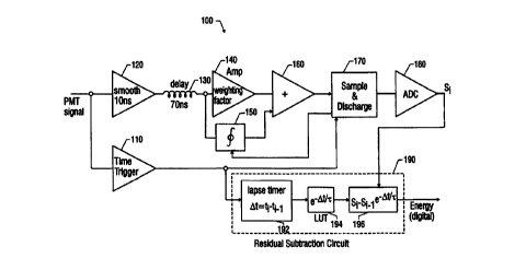
A block diagram of an exemplary embodiment of the present invention that
implements
this technique is shown in FIG. SA. As shown in FIG. SA, the exemplary pile-up
prevention
circuit 100 receives electrical signals from a photosensor (not shown in FIG.
SA) connected to
the input of the circuit. The pile-up prevention circuit (PPC) 100 includes a
timing trigger 110,
which provides a signal to the sample and discharge control circuit 170 and
residual subtraction
circuit 190 upon receipt of a signal. In an exemplary embodiment the timing
trigger 110 may
be a simple threshold discriminator or a delay-line clipping discriminator,
which minimizes
retriggering by the remnant signal of the same particle. Alternately, the
timing trigger 110 may
be another appropriate triggering device, for example, a Schmitt trigger. PPC
100 also includes
a smoothing circuit 120 to smooth the received signal. In an exemplary
embodiment, the
smoothing circuit 120 may be a filter, such as a low-pass RC filter or a slow
amplifier. Further,
in certain embodiments, a smoothing circuit may not be necessary. The smoothed
signal passes
to a delay circuit 130, which provides a desired delay to the signal before
application to the
calculation portion of the circuit. In an exemplary embodiment, the delay
circuit 130 may be a
delay cable or analog delay line integrated circuit. The delay circuit 130 may
provide for a
delay of between about 1 to 100 ns, and more preferably between about 5 to SO
ns.
As shown in FIG. SA, the calculation portion of PPC 100 includes amplifier
140,
integrator 150, and adder 160. The amplifier 140 amplifies the smoothed
signal, thereby
providing a weighting factor to the signal. As discussed above, in an
exemplary embodiment
the amplifier 140 amplifies the signal to 1000 electrons. In appropriate
embodiments, an
CA 02288788 1999-11-02
WO 98/50802 PCT/US98/09347
-14-
amplifier may not be necessary. The integrator 150 performs an integration of
the signal over
the exponential decay of the signal. The outputs of the amplifier 140 and
integrator 150 are
input into the adder circuit 160, which develops the sum of these signals. The
resultant sum is
forwarded to sample and discharge control circuit 170.
In an exemplary embodiment, the sample and discharge control circuit 170 may
be
comprised of a register or the like, and a control circuit, such as a fast
analog switch, FET
transistor, or the like. Upon a signal by time trigger circuit 110, the sample
and discharge
control circuit 170 passes the resultant sum to analog to digital converter
(ADC) 180. The ADC
180 converts the sum to a digital signal, which is then forwarded as the
weighted-sum signal to
the residual subtraction circuit 190, which subtracts any remnant signal from
previous radiation
events.
As shown in FIG. SA, the residual subtraction circuit 190 includes a lapse
timer 192,
which determines a OT (or time difference) corresponding to the time between
receipt of two
detected signals. The residual subtraction circuit 190 also includes a look-up
table 194 that
determines an exponential value based on the time difference. This exponential
value is then
multiplied by the previous sum signal S;-, (not shown). Finally, a subtractor
196 subtracts this
remnant sum signal from the sum signal S; relating to the present detected
signal to thereby
output a digital signal E; corresponding to energy value of the present
signal.
After sampling, the sample and discharge control circuit 170 discharges the
output of the
integrator 150 to zero immediately by sending a control signal upon receipt of
the signal from
the timing trigger 110 to a capacitor and switch (not shown) associated with
the integrator 150.
In operation, the timing trigger 110 senses the arrival of the initial burst
of scintillation
electrons from any gamma ray. Immediately, time trigger 110 sends a signal to
the
sample-and-discharge control circuit 170 to sample the weighted sum of the
previous gamma
ray and pass the sum signal to the ADC 180. Since the timing trigger 110 has
no delay,
whereas the sum signal processing branch is delayed (in an exemplary
embodiment, the delay
may be between about 1 and 100 ns, and more preferably be between about 5 and
50 ns) with a
delay circuit 130, the weighted-sum signal is sampled before the arrival of
the energy signal
CA 02288788 1999-11-02
WO 98/50802 PCT/US98/09347
-15-
from the next gamma ray. The delay is used to ascertain that the weighted sum
of the present
event is sufficiently discharged before the next event enters the i. tegrator
150.
Hence, pile-up of the next signal onto the present is prevented, and the
weighted sum
will not contain the energy of the next gamma ray. The delay also provides
enough time delay
for the sample-and-discharge control circuit 170 to discharge (to zero) the
previous integrated
signal from the integrator 150 before the arrival of the next signal, which
prepares the integrator
150 for the next signal. The discharge avoids pile-up of the old integrated
signal onto the new
integrated signal.
Since it takes a finite time for the electrical-charge output of the
integrator 150 to be
fully discharged to zero, especially if the previous event has high energy,
this discharging time
is the ultimate practical limit (processing dead-time) restricting the maximum
count-rate
performance of the present invention. In an exemplary embodiment, as shown in
FIG. SB, a
dual-integrator design ("ping-pong") may be used as the integrator, with each
integrator 150A
and 150B taking turns in processing each consecutive event as follows: when a
present event is
detected, the circuitry will be switched via switch 145 to integrator 150A to
integrate the signal
of the present event; when the next event is detected, integrator 150A will
stop integrating the
present event and the integrator output will be sampled. At the same time, the
circuits will
switch the second signal to integrator 150B for integration without waiting
for integrator 150A
to be discharged. Hence, integrator 150A is discharged in this idle duty cycle
when the
integration of the next event is performed by integrator 150B. This will
provide more than
enough time for the integrator 150A to discharge fully.
When a third event is detected, the signal will be switched back to integrator
150A,
which is fully discharged, for integration, and the integrator 150B is sampled
and discharged at
its leisure. Hence, with a dual-integrator "ping-pong" design, the discharging
dead time is
eliminated (to increase processing count-rate) and the error in energy
measurement due to
incomplete discharge is also eliminated.
As shown in FIG. SB, there may be two independent channels, each of which may
comprise an integrator 150A or 150B, an adder 160A or 160B, a sample-and-
discharge circuit
170A or 170B, or an ADC 180A and 180B, together with an input switch 145 and
an output
CA 02288788 1999-11-02
WO 98/50802 PCT/US98/09347
- 16-
switch 185 for selecting the processing-channel. Each channel takes turn to
process the next
incoming event. In other embodiments, there may be more than 2 channels
present. This also
provides an idle duty cycle for the integrators in each channel to be sampled
and fully
discharged. This dual-channel design also allows the use of a slower ADC (50%
slower) to
digitize the signals thus lowering cost.
The digital remnant subtraction circuit 190 may include a digital look-up-
table (LUT)
for determining the remnant scintillation energy (from all preceding gamma
rays) that the
scintillator is still emitting after the arrival of the latest gamma ray.
Specifically, the remnant
subtraction circuit 190 may include a register (not shown) to store a previous
weighted sum, a
LUT 192 for generating an exponential term, and a digital multiplication IC
(not shown). The
input to the LUT is the trigger-time of the present and the preceding gamma
ray (actually, their
time difference Ot). The digital energy output of the remnant subtraction
circuit 190 is thus the
pile-up free energy (E; ) of the detected gamma,
E;-S~-S~-Ieeu~ (2)
where S; is the weighted-sum relating to the present gamma ray, S;_I is the
weighted sum
relating to the preceding gamma ray, and Ot is the time interval between
arrival of the present
and the preceding gamma ray. S; and S;_i include the remnant signals from all
preceding
gamma rays. This is an exact equation, regardless of how many multiple pile-
ups exist in each
sum signal (see APPENDIX for the mathematical justification). The correction
term and the
exactness of this algorithm, being independent of the number of multiple-pile-
up remnants still
being emitted by the scintillator, are significant consequences of the present
invention. Thus,
the scintillation detector used in connecting with the present invention
permit count-rates that
produce 60% multiple pile-ups, since all the remnants from multiple pile-ups
can be easily
corrected for by equation (2). The present invention processes all incoming
events the same
way, regardless of whether it is a pile-up onto a previous event or whether
there is a pile-up
from the next event.
All the components in a circuit according to the present invention are basic
required
components of conventional detector electronic systems, with the exception of
the timing
trigger and the residual subtraction circuit. Therefore, the real-dme pile-up
CA 02288788 1999-11-02
WO 98/50802 PCT/US98/09347
-17-
prevention/correction provided by the present invention is an inexpensive
solution to the
problems inherent in the prior art. If there is no pile-up, the system
converges to a conventional
integrating circuit, as the sample and discharge control circuit 170 may be
set to pass the
resultant sum signal at a time approximately equal to 4T (i.e., approximately
1 ~s for the
NaI(T1) detector discussed herein). In case of a pile-up, it correctly
measures the energy of all
the pile-up gamma rays.
As long as the average time lapse (OT) of arrivals between two gamma rays is
longer
than the average detector integration time (Tc = 1 ~s), the average fraction
of scintillation light
collected will not diminish, which means the detected energy resolution will
not be
compromised. Hence, a NaI(Tl) scintillation detector employing the methods and
apparatus of
the present invention has the potential to count up to 1 x 10⁶ cps without
degrading the average
energy resolution. A traditional detector circuit with a deadtime of 1 p,s
must lower the
acceptable count-rate by 10 times, to 100,000 cps, to prevent the random
arrival of the next
gamma ray within 1 ~s of the present gamma ray (Nicholson, 1974). Poisson
statistics shows
that the non-pile-up fraction is 90% for 100,000 cps, which is why
conventional NaI(Tl)
detection systems cannot count over 100,000 cps. The present invention can
count even faster
than 1 x 10⁶ cps with some compromises in energy resolution.
The PPC of the present invention may be adapted for use with many different
detectors
and imaging systems. For example, the present invention may be used with
thyroid probe,
position sensitive detectors, or gamma ray detectors which detect neutrons,
charged particles
and gamma rays.
The conventional integration method (and its equivalent pulse-shaping method)
has been
the gold standard in the nuclear physics and nuclear medicine field for the
past 40-50 years.
The present invention is a significant breakthrough. This breakthrough can be
applied to many
nuclear detection areas, such as nuclear physics and engineering, high energy
physics, nuclear
medicine, industrial gauging, and oil field down-hole logging, among others.
Certain
applications will be discussed presently.
CA 02288788 1999-11-02
WO 98/50802 PCT/US98/09347
-18-
Nuclear Medicine Applications
The present invention has special attributes that make it particularly
applicable to
medical imaging, and especially gamma cameras. When a gamma ray hits a
detector in a
gamma camera, both energy and position information are needed for creating the
image. The
energy information discriminates (or qualifies) the useful imaging gamma ray
from background
gamma rays which have been scattered around in the body being imaged
(scattering lowers the
gamma energy). When a detected gamma is qualified by its detected energy, the
position
information locating the point of detection of the gamma ray has to be
determined to create a
gamma ray map (image).
The pile-up prevention circuit (PPC) of the present invention can determine
the gamma
1 S ray energy, despite pile-ups. However, the present invention would be less
useful for gamma
cameras if it could not also determine the gamma ray position in pile-up
situations. A particular
embodiment of an apparatus according to the present method may be incorporated
into a regular
gamma camera to determine position information, as well as energy information
in a pile-up
sltuatlon.
This embodiment may be known as a position-energy pile-up prevention (PEPP)
algorithm and circuit. This solution is compatible with existing gamma camera
electronics.
Compatibility is important because it allows the pile-up-prevention circuit of
the present
invention to be applied to present gamma cameras without major modification to
their existing
front-end electronics.
A regular gamma camera and its electronics generate five signals of interest
for the
present invention, namely X+, X_, Y+. Y_, and Z. Z is the energy of the gamma
ray. The
X-position and Y-position of the gamma ray can be calculated from these five
signals,
X=(X+-X_)~Z (3)
and
Y = (Y+ - Y_) ~ Z (4)
CA 02288788 1999-11-02
WO 98150802 PCT/US98109347
- 19-
The prenormalized positions are defined as X' _ (X+ - X_ ), and Y' _ (Y+ -
Y_). Hence, the
X-position and Y-position can be calculated by a subsequent normalization with
Z:
X=X'/Z (5)
and
Y=Y'/Z (6)
In addition to preventing energy pile-ups in scintillator-PMT's, the same PPC
circuit
may be applied directly to the prenormalized position signals, X' and Y', to
prevent pile-ups by
generating pile-up-free X' and Y'. The mathematical proof of this property can
be found in the
APPENDIX. With the realization of this important property, the PPC circuit of
the present
invention may be connected to the prenormalized positioning signals X' and Y'
in a regular
camera, as well as the energy signal Z' (a fast instantaneous signal sum of
all the PMT's), as
shown in FIG. 6, to generate three pile-up-free signals X', Y' , and Z' for
calculating the energy
and position of the detected gamma ray despite multiple pile-ups.
The system of FIG. 6 includes a conventional gamma camera 200, which develops
prenormalized position signals X' and Y', and energy signal Z'. Each of these
signals is input
into a separate pile-up prevention circuit (PPC) 210. This PPC 210 may be the
same circuit as
discussed above, in connection with FIGS. SA or SB, or it may be a slightly
modified version
(as shown in FIG. 6, certain components of the circuit of FIG. SA have been
deleted for
illustrative purposes). First the PPC 210 may not have a time trigger, as
trigger signals for this
embodiment may come directly from a fast trigger 220, which is input to all of
the PPC's 210.
This fast trigger 220 is a new addition to a conventional gamma camera.
Further, the individual
PPC's 210 may not have a remnant subtraction circuit, as all signals output
from each PPC 210
may be input into a digital signal processor (DSP) 240. In an exemplary
embodiment, the DSP
240 may include the remnant subtraction algorithm for the X', Y', and Z
signals. The DSP 240
provides for faster processing. However, in certain embodiments, it may be
possible to have the
lookup tables within the individual PPC 210 units. The DSP 240 may also
include other
corrections (energy and distortion corrections) for the X', Y' and Z signals,
and X, Y
renormalization process.
CA 02288788 1999-11-02
WO 98/50802 PCT/US98/09347
-20-
The system of FIG. 6 also includes a coincidence timer 230, which receives a
trigger
signal from the fast trigger 220. Upon receipt of the signal, the coincidence
timer 230 sends a
time clock signal to FIFO's 235, which is transmitted to the DSP 240. This
time clock signal is
for pile-up remnant subtraction and for coincident timing measurement in
positron coincidence
imaging (PET).
As discussed above in connection with FIG. SA, the prenormalized position
signals (X',
Y') obtained from gamma camera 200 are delayed, amplified, and integrated
within the PPC
210. The amplified instantaneous position signals TX'(t) and TY'(t) are summed
to their
integrated position-signal, j X' (t)dt, ! Y' (t)dt, respectively, also within
the PPC 210. These
weighted sums of prenormalized positions are immediately sampled by a fast
analog-to-digital
1 S converter (ADC) within PPC 210, just before the onset of the next pile-up
event. The arrival of
the next gamma ray is sensed by the fast trigger 220, which monitors the fast
instantaneous total
energy output, Z'. After the ADC sampling, the integrator circuit of PPC 210
is immediately
discharged so that it can start integrating the position signals coming from
the next pile-up
gamma ray. Alternatively, there may be two matching integrators taking turns
in processing
each consecutive signal to allow for an idle duty cycle for discharging the
integration to zero.
Further, as discussed above, there may be two matching channels of amplifiers,
integrators,
samplers, and ADC's to handle each successive event to allow the integrators
in each channel to
discharge to zero.
The fast trigger 220 also marks the arrival time of all gamma rays. The timing
mark is
generated by a fast clock, which in an exemplary embodiment may be a 250 MHz
clock. These
arrival times are sent to the DSP 240 for remnant signal subtraction and for
positron
coincidence detection in PET imaging. The remnants of position signals,
generated by the
residual light output of all preceding pile-up gamma rays, will be subtracted
from the present
position weighted-sum in the DSP 240 in FIG. 6 using a LUT that stores the
exponential term in
the following remnant subtraction operation to determine the remnant position
signal to be
subtracted from the j-th event:
Rp~ - SPA-~ e-tec>n
and
CA 02288788 1999-11-02
WO 98/50802 PCT/US98/09347
-21 -
Xj,' = SPA - RPM (8)
where SP~_i is the last position-weighted sum and 0t is the time-lapse between
the j and the j-1
position signals. This remnant subtraction strategy automatically subtracts
for all higher levels
of multiple pile-ups. After the remnant subtraction, the DSP 240 calculates
the normalized
positioning estimation, X = X' / Z and Y = Y' / Z , where Z is the total
energy after remnant
correction of the present event. Alternate methods of remnant subtraction may
include
performing the process within the individual PPC 210 units. The DSP 240 also
performs the
regular correction processes for linear distortion, field nonuniformity, and
regional
signal-pulse-height variation, in real time. The host processor 250 is for
image display and
operatorinterface.
1 S An apparatus according to the present invention thus decodes the position
and energy of
each detected event. The fast trigger 220 detects the arrival of an event, and
triggers a
time-mark output in the coincidence-timer 230 for the event's arrival time.
This event-arrival
time mark will be used to calculate the prenormalized positions and energy.
The calculation
may be performed by the DSP 240, where exponential functions may be stored as
a
look-up-table. The DSP 240 also performs the energy normalization on the
prenormalized
positions to provide the true position signals. In this processing scheme, all
the events
(photopeak or true events, and scatter noise events) are included in the
processing to calculate
all the remnant signals from previous events, and an event's real energy is
not known until after
processing. Hence, the energy acceptance of an event has to be made after the
decoding
operation, in/after the DSP 240. If the decoded energy is higher than that of
the scatter radiation
noise signal, the detected radiation is accepted as a true (photopeak) event.
The output of the
DSP is thus the pile-up-free, energy-normalized positions (x, y) and gamma-
energy (z). Since
all data acquisition computers in gamma cameras accept the standard signals of
(x, y, z), the
proposed processing algorithm and electronic architecture is compatible with
existing data
acquisition computers. This compatibility is useful to adapt the scheme to
existing cameras.
Implementation of the present invention in a conventional camera is very
feasible, as
shown in FIG. 6. A DSP circuit is standard in most cameras for processing
position signals and
for distortion correction. Thus, the only additional circuits needed for
incorporating the
methods of the present invention into a regular camera are the three channels
of PPC circuits
CA 02288788 1999-11-02
WO 98/50802 PCT/US98/09347
-22-
according to the present invention, a fast trigger circuit, and a clock, which
increase production
costs by only a few hundred dollars to achieve a 10-20 times increase in count-
rate capability.
Such an increase in count-rate capability would permit or improve the
following
imaging procedures:
(a) Positron imaging, because it requires the removal of a lead collimator
from a
gamma camera, which exposes the NaI(Tl) detector to a 10-fold or more gamma-
ray flux. This
forces an injected positron tracer dose to be reduced by 5-lOx to prevent
significant pile-up in a
regular camera. With the present invention, it would not be necessary to
reduce the injected
dose. The positron image quality would be significantly improved as a result
of this 5-10 times
increase in positron counts in the image. Imaging time can also be decreased
as a result of the
increased count-rate capability;
(b) Imaging radionuclide therapy patients to deduce actual radiation dose
delivered
to tumors and organs so that radionuclide therapy can be improved;
(c) Dynamic first-pass cardiac imaging to study shunts, valves, the right
heart and
lung;
(d) The use of very short half life tracers to reduce radiation dose and
increase
patient throughput;
(e) The use of larger NaI(Tl) detectors to reduce scanning time for whole-body
imaging;
(f) Acquiring very high count-rate transmission data while the emission data
is
being collected. In such a scheme, a lower energy gamma source is used for the
transmission
data; the very high-rate transmission collection is used to minimize the
effect of 'down scatter'
contamination from the emission gamma. Other improvements in medical imaging
would also
be produced by application of the present invention.
The present invention also provides for further improvement of the detection
rates of a
gamma camera. In this embodiment, the camera signals may be split
geometrically into 4 or
more independent signal processing zones as if four independent cameras
existed adjacent to
CA 02288788 1999-11-02
WO 98/50802 PCTNS98/09347
- 23 -
each other. More specific details of such a system are disclosed in U.S.
Patent No. 5,319,204
and, U.S. Patent No. 5,453,623, the disclosures of which are hereby
incorporated by reference.
The incorporation of the PEPP (position and energy pile-up prevention)
algorithm of the present
invention into such a multi-zone design would further increase the count-rate
capability of the
camera by two or three times.
Multi-zone designs have been proposed and implemented in NaI(Tl)-based PET
cameras
to increase maximum count-rate capability (Muehllehner et al., 1995;
Muehllenhner and Karp,
1986; Karp et al., 1986; Freifelder et al., 1994). These designs depend on the
fact that most of
the scintillation light is distributed only to the neighboring 7-9 PMTs.
For a camera with 36 PMT's (6 x 6 configuration), the camera may be divided
into four
identical square zones, identified as K, L, M, N, as shown in FIG. 7. Each
zone therefore has
nine PMT's (3 x 3). Each zone may be treated as an independent camera with its
own PEPP
circuit according to the present invention to correct for pile-ups and image
distortions. The nine
PMT's in each zone may be grouped into one signal-triggering line. With four
zones, there
would be four signal-triggering lines, S~, SL, SM, SN. If the first gamma ray
is detected in zone
K, the PEPP circuit of zone K would be turned on to measure its position and
energy. If a
second gamma is detected in zone K within the pile-up time, the PEPP circuit
would correctly
measure the position and energy of both gamma rays.
If the second gamma ray strikes zone L while zone K is processing a prior
count, two
scenarios may occur. These two scenarios are addressed in detail:
(1) In the first scenario, the gamma rays detected in zone K and zone L are
both far
from the zone boundaries between K and L, such that there is little light
spilled from one zone
to the next. Hence, there is little or no signal interaction between the two
events to cause
positioning errors. Both gamma rays may be processed independently by the PEPP
circuit of
each zone to obtain the correct energy and position.
(2) In the second scenario, the first gamma ray detected in K is so near the K-
L
boundary that the PEPP circuits in both zone K and zone L are triggered, as
shown in FIG. 8.
In this case, zone K may decode a valid position, but zone L would decode an
artifact-count at
the K-L boundary near the event in K, as shown in FIG. 8. When the second
gamma hits zone
CA 02288788 1999-11-02
WO 98150802 PCT/US98/09347
-24-
L later, at location A in FIG. 8, the remnant signal of the fictitious count
created in the L-PEPP
. circuit would be subtracted from the signal of the second gamma ray (A), so
that there is no
interference in determining the position of the second gamma ray. Thus, in
this scenario, both
the first (K) and second (L) gamma rays would be correctly measured, but an
additional artifact
count will be created at the K-L boundary.
With these inter-zone light-spill considerations, the processing circuitry for
the
mufti-zone pile-up prevention (MZPP) camera is shown in FIG. 9. As shown in
FIG. 9, each
zone may have its own PEPP circuit 310. In addition, each zone may have its
own DSP 315.
These four PEPP circuits may be monitored by an inter-zone coincident
detection circuit 330
and a mufti-trigger processor 340. The interzone coincident detection circuit
receives input
from the fast timing triggers of each of the zone PEPP circuits 310. The mufti-
trigger processor
340 receives zone position signals from each of the zone PEPP circuits 310. In
an exemplary
embodiment, the processor 340 may be a DSP. The output of processor 340 is
input into a main
DSP processor 350, which provides information to image buffer 360, interface
370 and Host
CPU 380. The main DSP processor 350 serves two functions: (1) it merges the
four
zone-images into one image, and (2) it performs a final distortion correction
for the combined
image.
To eliminate the problem of additional artifact counts at a border, the
interzone
coincidence-triggering circuit 330 (between any two or more zones) may be used
to detect the
simultaneous triggering of two or more zones caused by an event detected near
the boundary.
When two or more neighboring zones are triggered by a single event near the
boundary, the
PEPP circuit 310 in each zone would respond (as originally designed) as if an
independent
event is detected in each zone by generating their own position signals,
(XK+ xK ) ~ ZK (8)
and
3U XL=(X +-XL)~Z (9)
Furthermore, the simultaneous triggering of both zones would also activate the
inter-zone coincidence circuit 330 which would then feed these two or more
independent
CA 02288788 1999-11-02
WO 98/50802 PGT/US98/09347
- 25 -
position signals into mufti-zone-trigger processor 340, which performs a
centroid averaging for
these two or more position signals. Mathematically, this averaging is
equivalent to combining
the two or more zones and using the regular Anger positioning method over this
larger domain,
as shown in the following equation:
X=~XKZK +XLZL~I(ZK +ZL)= ~ (XK+ -XK_)+~XL+ -XL_) } /~ZK +ZL) (lO)
This averaged position is stored in the main processor 350 that stores the
composite
camera image (four zones combined), whereas the individual zone position
signals (XK and XL)
are discarded. This method thereby eliminates the boundary-artifact event and
also provides a
better estimation of the position, since all of the scintillation light
emitted would be used for
computing the position (including light spilled into the adjacent zone).
Inter-zone light spill also exists in the two high count-rate cameras using a
mufti-zone
design because, as long as a single NaI(Tl) crystal is used, light will be
distributed from one
zone to the next. Technical solutions are readily achievable as indicated by
ADAC MCD and
UGM SPECT and PET cameras (Muehllehner et al., 1995; Glass et al., 1996;
Freifelder et al.,
1994). The present invention, using a monitor to detect coincidence triggering
of two zones is
simple, straightforward to implement, and usable with the pile-up prevention
technology of the
present invention.
An increase in detection rates by 2-3 times is expected over the single-zone
implementation, if the distribution of the scintillation light is mainly
limited to a circle 4.5" in
diameter centered on the point of detection. When this light-spread condition
is met, only the
gamma rays hitting the shaded area shown in FIG. 10 can trigger or affect both
zones. Hence,
the probability that a gamma ray will hit the independent area is 21/36, while
the probability
that it will hit the light-spill-over area is 15/36. Thus, the count-rate
enhancement obtained by
splitting the camera signals into 4 zones is (21/36) x4 or 2.3 times.
Shown in FIG. 19B is a flow chart for the method of the present invention
relating to
this mufti-zone pile-up prevention embodiment. As shown in FIG. 19B, an
instantaneous
detected signal is provided to four independent PEPP's in step 410. Then it is
determined
whether this signal creates a mufti-trigger event in step 420. If it is not a
mufti-trigger event,
CA 02288788 1999-11-02
WO 98/50802 PCT/US98/09347
-26-
control passes to step 430, in which it is determined whether it is a single-
trigger event. If it is a
single-trigger event, control passes to step 440 and single active zone
position processing is
performed, as discussed above.
If it is determined that it is a mufti-trigger event, in step 450 active zones
are combined
into a larger domain for processing. Then, the large domain position
processing is performed in
step 460, as discussed above. The result of either path of this method results
in a determination
of the true and accurate position of the instantaneous signal in step 470.
Combining the pile-up prevention method and the mufti-zone method, the count-
rate of
a camera according to the present invention may reach 4,000,000-5,000,000 cps.
With
optimization and further development of the PEPP circuit as discussed earlier,
the count-rate
may be extended further. Monte Carlo simulation indicates that 2 x 10⁶ cps is
achievable with
the pile-up prevention method alone, and a combined count-rate of 2.3 x 2 x
106 = 4.6 x 10⁶ cps
may be achievable, a significant improvement over the 105 cps achievable in a
regular camera.
The present application of scintillation detectors can be divided into four
main areas:
(i) industrial gauging, including thickness, level and density gauging;
(ii) surveying, including oil field logging, nuclear reactor monitoring,
nuclear
fuel cycle monitoring and airport luggage inspection for explosives;
(iii) research applications in nuclear physics, high-energy physics, medicine,
and industry; and
(iv) medical uses (gamma cameras, PET cameras, bone scanners, thyroid
probes, general purpose probes, monitors, and dosimeters).
A new and potentially important application of the present invention is in
airport
surveillance to look for plastic explosives in luggage using, for example,
neutron activation
techniques. The ability to detect radiation 10-20 times faster would allow (a)
detectors to be
used in a much higher radiation areas to extend the usefulness of the detector
system, (b) the
ability to count faster would increase the speed of data acquisition to
shorten the data collection
time, e.g., in an airport bomb surveillance system, a 10-20x stronger neutron
source can be used
CA 02288788 1999-11-02
WO 98/50802 PCT/US98/09347
-27-
to scan luggage faster, so that luggage scanning times can be reduced by 10-20
times to
improve throughput.
In industrial gauging application, the scintillation detector is used in
conjunction with
radiation sources to measure the quantities or density of materials being
processed. For
example, while molten cement or molten metal is poured into a container, a
nuclear level gauge
may be used to stop the pouring process when a specific level is reached.
Another example is
"thickness gauges" using gamma-ray backscatter detectors in thin-film
processing in the plastic
and paper manufacturing industry (especially for high-value films such as
video-tapes and
electronic capacitor films). Quite often, the film to be scanned is
manufactured in large-area
sheets, and the detectors together with the radiation source must scan the
entire sheet. The
detector's ability to detect gamma rays at very high count-rate (10-20x) means
that a very
intense gamma-ray source (10-20x) can be used, which in turns translates to a
10-20x faster
data acquisition. Thus, the time spent on the inspection-scanning processes or
manufacture-control processes can be reduced by 90%, thereby increasing
production rate.
Scintillation detectors are also widely used in radiation monitoring in
nuclear reactors,
and in oil field borehole logging to survey rock/hydrocarbon structures along
the borehole in oil
exploration. A faster counting system would increase the information collected
or decrease the
data collection time, which would lower the cost of data acquisition (oil rig
time is very
expensive).
Scintillation detectors are also widely used for nuclear applications, for
example: (a)
reactor monitoring of liquid and gaseous streams to look for isotopes, (b)
fuel rod cladding
failure, (c) isotope scanning for irradiation fuel to determine power
distribution and migration
of fission products in the reactor core, (d) reactor fuel fabrication and
quality control, {e) spent
fuel reprocessing, and (f) management of nuclear waste. Since these nuclear-
reactor related
detectors are used in very high radiation flux areas, this high count-rate
invention is potentially
very useful in the nuclear energy business.
In research laboratories, a faster counting detector system is always welcome,
as it
allows new experiments to be performed. Nuclear-electronics instrumentation
companies that
CA 02288788 1999-11-02
WO 98/50802 PCT/US98/09347
- 28 -
S market detector electronic modules for research laboratories may wish to add
this electronic
.invention to their catalog.
In medical imaging applications, present gamma cameras are adequate for
imaging
diagnostic quantities of single photon tracers, but their limited count-rate
capabilities introduce
image artifacts and count-loss, and degrade image quality when gamma ray flux
is high. These
situations may occur in:
(a) positron imaging, which exposes the NaI(Tl) detector to a 10-fold
or more gamma-ray flux, with the removal of the lead collimator from a gamma
camera for positron imaging;
(b) imaging radionuclide therapy patients to deduce the actual
radiation dose delivered to tumors and organs for improving radionuclide
therapy treatment;
(c) dynamic first-pass cardiac imaging to study shunts, valves, the
right heart and lung;
(d) the use of very short half life tracers to reduce radiation dose and
increase patient throughput;
(e) the use of larger NaI(Tl) detectors to reduce scanning time for
whole-body imaging; and
(fj acquiring very high count-rate transmission data while the
emission data is being collected (the very high-rate transmission collection
minimizes the effect of 'down scatter' contamination from the emission gamma).
With this invention, the count-rate capability of gamma cameras can be
enhanced by
20-40 times, which would allow (or improve upon) the above useful imaging
protocols. The
new capability may reduce reliance on the use of PET costing $2,600,000 to
purchase and
$250,000/yr to operate. Another application of the present invention is for
the low-cost, high-
resolution PET detection system of PMT-quadrant sharing design, as shown in
U.S. Patent Nos.
5,319,204 and 5,453,623, to compensate for its lower count-rate.
CA 02288788 1999-11-02
WO 98/50802 PCTNS98/09347
-29-
Thus, the present invention will open up new and exciting clinical
applications for
gamma cameras, which is especially important in today's healthcare environment
when clinics
must perform more with less money.
The following examples are included to demonstrate preferred embodiments of
the
invention. It should be appreciated by those of skill in the art that the
techniques disclosed in
the examples which follow represent techniques discovered by the inventor to
function well in
the practice of the invention, and thus can be considered to constitute
preferred modes for its
practice. However, those of skill in the art should, in light of the present
disclosure, appreciate
that many changes can be made in the specific embodiments which are disclosed
and still obtain
a like or similar result without departing from the spirit and scope of the
invention.
WORKING EXAMPLES
In studies with an exemplary embodiment, the present invention was used in
connection
with a 3"x 4" NaI(TI) scintillator with a photomultiplier from Ortec
Corporation (Oak Ridge,
TN). This detector was connected to ( 1 ) regular detector electronics setup
using a
pulse-shaping amplifier {0.5 ps shaping time) and a multi-channel analyzer,
and (2) to the pile-
up prevention circuit ("PPC") of the present invention.
The circuit may be interfaced to a computer. For example, the present
invention was
connected to a PC computer with a 133 MHz PENTIUM processor and a high-speed
input/output board for the studies. The data acquisition software was written
with LABVIEW
(National Instruments, Austin, Texas). A 99"'Tc point source (140 KeV gamma
ray) in air was
used for all the count-rate studies. The pile-up-prevention circuit of the
present invention may
also be used to measure the number of nonpile-ups, single pile-ups, and
multiple pile-ups.
For comparison studies, circuits implementing three methods were setup and
tested.
The methods included: {i) the pulse-shaping method (SOOns); (ii) delay-line
clipping (256 ns);
and (iii) the method according to the present invention. The pulse-height
spectra, energy
resolution and acquired true-count fractions were collected as a function of
true-even rates using
a 99mTC (140 KeV) point source, which decays with a 6 h half life. This half
life was used to
calculate the true-even rate impinging the detector when very high count-rate
data were
acquired.
CA 02288788 1999-11-02
WO 98/50802 PCT/US98/09347
-30-
A. EXAMPLE I
The pulse height spectra of 99mTc (140 KeV gamma-ray) for the pile-up
prevention
circuit of the present invention and the pulse-shaping method (SOOns) are
shown in FIGS. 12A
and 12B. FIG. 12A show results of the pulse-shaping method, and FIG. 12B show
results of the
present invention. At 50 Kcps, both measured 10.9% energy resolution. At 120
Kcps, the
pulse-shaping method (FIG. 12A) started to demonstrate pile-up at the higher
energy side and
distortion at the lower energy side. Above 200-300 Kcps, the spectra were not
usable. The
PPC method spectra (FIG. 12B) maintained the spectra shape even at 2 Mcps.
This first study
demonstrated that the method of the present invention can significantly extend
scintillation
counting rates. However, the energy resolution was poor at 2 Mcps for this
first study. Part of
the reason was due to DC-level instabilities because the resistor divider of
the photomultiplier
(PMT) in the ORTEC probe was AC-coupled and the biasing-current was not
designed for such
a high count rate (there was no reason to design for such high rates
previously because of
NaI(TI) pulse pile-up). Another reason was that the prototype board
incorporating the apparatus
of the present invention was built on a simple board with holes and the wiring
was done with
wirewrapping wire. A third reason was that a single integrator was used, which
may not have
been sufficiently discharged if the last event had a very high energy. Both
the PMT divider and
the prototype circuit were subsequently improved. Dual integrators and ADC
channels ("ping-
pong") were provided to assure complete discharge of the integrators. The
pulse height spectra
were measured again for the method of the present invention, and the energy
resolution was
significantly improved, as shown in FIGS. 13A-D. Even at 2 Mcps (FIG. 13C),
the energy
resolution achieved 1 S% compared to 10.9% at SO Kcps; part of the reason for
this difference is
the shorter average signal collection time when the count rate is very high.
At lower count
rates, the integration time for most pulses were integrated to 1 ps, while at
2 Mcps, the average
time-lapse between events was 500 ns which implies that the average signal
collection time
would be equal to or less than 500 ns.
B. EXAMPLE II
In a second study, the method of the present invention was compared with a
delay-line
clipping (DLC) experimental setup (using NIM electronic modules and a 256 ns
clipping). The
energy resolution results are shown in FIG. 14. At lower count rates, the PPC
method had
better resolution than the DLC method, while at 2 Mcps the energy resolution
was about the
CA 02288788 1999-11-02
WO 98/50802 PCT/US98/09347
-31 -
same. The study also generated the photopeak-count rates, . i. e. the non-pile-
up good counts
acquired by each method using a narrow energy window, as a function of true-
count rates, as
shown in FIG. 15. For the method of the present invention at 2 Mcps, the
photopeak counts
were 85% of the total incident counts, while the DLC had only 25% good counts.
The low
photopeak fraction in the DLC method was due to a high 75% count-loss due to
pile-ups which
placed the pile-up-event energy above the photopeak acceptance-window. The DLC
method
delayed the occurrence of pile-up due to its shorter pulse width, but at very
high count rates, its
fixed pulse-width still made it more vulnerable to pile-ups (FIG. 16) than the
PPC method,
which has a variable signal-integrating time and count-recovery capability.
Hence, the
photopeak counts collected by the PPC method is 3.3 times more than the DLC
method at
2 Mcps. The pulse-shaping method only maintained 35% at 0.25 Mcps, and there
was no useful
photopeak data above 0.25 Mcps because of pile-ups (FIG. 15).
The importance of an effective remnant light subtraction for every triggering
event is
demonstrated in FIGS. 17A-F, especially at very high counting rates. At 600
Kcps, a simple
weighted-sum method (SWS) without remnant subtraction yielded an acceptable
but worse
spectrum compared to the present invention. However, at high counting rates 1-
3.5 Mcps, the
energy measurement errors of SWS are significant. Above 2 Mcps for NaI(TI),
most events are
riding on the signal of other events (see Table 2 and FIG. 16), and SWS would
measure large
energy errors on most events and cause severe count-loss outside the photopeak
acceptance
window. The SWS energy measurement errors demonstrated here (shaded spectra in
FIGS. 17A-F) should be similar to that shown in U.S. Patent No. 5,430,406
discussed above.
FIGS. I S-17 demonstrates the count and energy recovery/restoration
capabilities of the present
invention.
C. EXAMPLE III
As shown in FIGS. 18A-C, a Monte Carlo simulation of the torso (with liver,
kidneys,
and bladder) was performed to demonstrate the effect of pile-ups in imaging at
2 Mcps for: (a)
the method of the present invention (FIG. 18A); (b) the pulse-clipping method
(256 ns) (FIG.
18B); and (c) the regular fixed integration method (1 p.s) {FIG. 18C). The
study simulates the
electronic processing of each method in a gamma camera. The results are shown
in FIGS. 18A-
C. At 2 Mcps, the present invention method showed all the uptake organs; the
conventional
CA 02288788 1999-11-02
WO 98/50802 PGT/US98/09347
-32-
method shows no organs; the pulse-clipping result was in between the two, with
high pile-up
artifacts between the two kidneys and diminishing activities in the bladder
and kidneys.
Besides preventing measurement errors from pile-ups, the present invention
allows data
acquisition time to be shortened significantly. This fast data acquisition is
important in
commercial/medical applications, as data acquisition time can be significantly
reduced. As
discussed above, the count loss with the conventional method is very high
above 160,000 cps
and saturates at 200,000 cps. Although the data appears to indicate that the
conventional
method can approach 200,000 cps, the pile-up fraction at this limit is very
large, and the
photopeak is badly distorted. Therefore, a large percentage of the data is not
useful. The
present invention can count over 2,000,000 cps with very little count loss,
while preserving a
very good photopeak, and all of the data is useful. Thus, the present
invention is a significant
improvement over the prior art.
Data from an embodiment of the present invention demonstrate that the
invention
significantly improves measurement of the energy of gamma rays at very high
count-rates, even
when multiple pile-up approaches 60% and single pile-up approaches 17%
(nonpile-up at only
13%) at 2,000,000 cps. The data indicate that a 10-20 fold improvement in
count-rate
capability is feasible with the present invention.
These studies discussed above showed that the methods of the present invention
are
feasible. Compared to the pulse-shaping method, it has a 15 times higher
counting rates, and
yet at low counting rates, the PPC energy resolution is the same as the
standard pulse-shaping
method. The PPC energy resolution only degraded slowly from 10.9% at 50 Kcps
to 15% at
2000 Kcps. Compared to the pulse-clipping technique, the PPC method has better
energy
resolution at regular count rates (10.9% vs 15%) and 3.3 times higher
photopeak (non-pile-up)
counts at 2000 Kcps. The count and energy recovery capability of the present
invention at very
high count rates is important for extending the maximum count rates of
scintillation detectors.
All of the methods and apparatus disclosed and claimed herein can be made and
executed without undue experimentation in light of the present disclosure.
While the
compositions and methods of this invention have been described in terms of
preferred
embodiments, it will be apparent to those of skill in the art that variations
may be applied to the
CA 02288788 1999-11-02
WO 98/50802 PCT/US98/09347
-33-
methods and apparatus and in the steps or in the sequence of steps of the
method described
herein without departing from the concept, spirit and scope of the invention.
All such similar
substitutes and modifications apparent to those skilled in the art are deemed
to be within the
spirit, scope and concept of the invention as defined by the appended claims.
APPENDIX
(1) Energy Pile-up Prevention Formulae Algebra
Suppose at time t~, a j-th gamma ray (y~) is detected. The j-th gamma ray is a
pile-up
event on top of two preceding gamma rays y~_) and y~_2. From Knoll, 1979, the
instantaneous
scintillation emission of a scintillator after detecting a gamma ray is
~(t) = E 2-cr.i; )m ( 1 )
T
1 S where E is the total scintillation signal generated by the scintillator,
and E is proportional to the
energy of the gamma ray detected. The instantaneous signal at time t~ for t~ <
t < t~+1, contains
emission from three gamma rays y~-2, y~-~, y~, and is given by,
~'{t~ ° E' e'~~ y)/T + E, ~ e.c~ ~,_~)/t + E, 2 e-c~-';-Z)/t
i i i
- Ej e-tr-~;)/_ + Ej-~ e-cl-,.~)/= e~c~-~;)/~ + Ei-2 e-cl-~;.=)/z e-tr-',)/T
(2)
z T T
__ ~~ j + ~ j-' e-(~; r;.i)/t + ~ - e-(~;-~;.x)/i~~ 1 a (r;-r;_i)/iJ (3)
If q(t) is amplified or weighted by an amplification factor T:
'~q~t~ _ ~E~+E~_1a(''-'e,)/=+E _ a(';-.;.:)/_~~-('-';a=~
j 2
If q(t) is only integrated from t~ to t (this implicitly means that the
integrator was
discharged or zeroed just before t~) from equation (3),
~,(u~u = ~~+~~-~e c';-~;.~)n +E _ a c';-';.Z>i=~~-a ~'-'Oi=~
l~ j 2
CA 02288788 1999-11-02
WO 98/50802 PGT/US98/09347
-34-
If equation (4) and (5) are summed, the weighted sum within the time period of
gamma-ray y~
will be:
,s; = iR'{t)+ ~ 9{uluu = E; + ~;_, + E;_Ze ~'' ~ ''-~ )/T J2 ~'' /'-' )/T (6)
The same analysis is now applied to the preceding time period where t~_~ < t <
t~ (the time period
of y~_1). From equation (1) and FIG. 13, the instantaneous signal after the
onset of y~_~ is:
to q{r)= E'-' a ~ -t,-~)~T + E'-2 a (r -r,-Z)/T
T 'C
The weighted sum for this period is:
S;_i =~9{t)+ ,~ 9{u
;_. (8)
Hence S~_, is the term inside the square bracket of equation (6), and equation
(6)
becomes:
Ill /l-1 )/T
S; = E; + S;_. a
- ll.I%_I IT
or E; _ S; - S;_~ a (9)
Hence the energy deposition of the j-th gamma ray can be derived from the j-th
weighted sum minus the preceding weighted sum decreased by a emission decay
factor,
provided that the integrator is discharged immediately before the arrival of
the j-th gamma.
Note that the weighted-sum Sj as shown in equation (6) is not a measurement of
energy of the
j-th event, it is the measurement of the total energy trapped inside the
scintillator just after the
j-th event hit; i. e., S~ includes the energy of the j-th event and all the
remnant energy of previous
multiple-pile-ups when the j-th event is deposited.
Equation (9) is an exact solution, regardless of how many previous gamma tails
on
which the j-th gamma is riding. The present invention thus provides the first
method that
CA 02288788 1999-11-02
WO 98/50802 PCTNS98/09347
-35-
attempts to recover all triggering events and compensating for multiple-pile-
up exactly. Thus,
the present invention may achieve higher count rates than possible with known
methods.
Equation (9) can be easily understood intuitively. If there is no pile-up, S~
is the
detected energy of the j-th gamma ray (independent to when S~ is sampled). If
there are pile-
ups, S~ is the total energy in the detector in the j-th period (independent to
when S~ is sampled),
which includes the detected energy of the j-th gamma ray and the remnant
emission of all the
preceding gamma ray. This j-th remnant emission is simply the total energy in
the preceding
period (S~_,) decreased by the emission decay factor governed by the time
difference between
the j-th gamma and its preceding gamma.
(2) Pile-up Prevention Formulae for Gamma-Camera Anger-Positioning
1 S In Anger-position method, assuming that no pile-up occurs, the y-location
is estimated
by the centroid calculation:
X~Ea X'
X = ' -- ; Z=_ ~~E; (10)
~~ E; Z
where E; is the total signal received by Photomultiplier-i (PMT-i) when a y-
ray is detected, and
X; is the physical location of PMT-i. X' is the prenormalized pseudo-position
signal which
needs to be normalized by the total detected energy Z of the y-ray, to
generate the centroid
location X. X' can be defined as:
X' --_- X+ - X_
If at time tJ, the first y-ray with energy Zl is detected, the total energy
(after signal integration)
distributed to PMT-1, PMT-2, . . . , PMT-n are Eli, E~2, . . . , El",
respectively. The total
integrated energy detected by the camera is:
Z, =~~E,; (11)
From equation (10), the prenormalized position X' for conventional Anger
positioning
is:
X; =~~X;E,; (12)
CA 02288788 1999-11-02
WO 98/50802 PCT/US98/09347
-36-
S In conventional Anger-position, E~; in equation (12) are the integrated PMT
signals
. (integrated for 0.6-1 ps}, and therefore X'~ in equation (12) is a static
quantity obtained after a
fixed 1 p.s integration time. Hence, if there is a pile-up during the
integration time, X', will be
wrong. In the method of the present invention, the instantaneous prenormalized
position X'(t) is
used:
X; (t~ _ ~ X! Eu a (~-~, )lt
' T
The weighted instantaneous prenormalized position is:
,~.~(t~ _ ~I X~E~~ G-(~-~')l~ (13}
The integrated prenormalized position is:
Xi y~du = ~ X; E~, (~-a ~t t'~~T } (14}
,
If equation (13) and (14) are summed, the weighted Sum ofX',(t) is given by:
SX; = zX;(t~+ ~ X;~u~du= ~ X;E,, (15)
From equation (12) and equation {15), we obtain SX; = X; . Hence , if the
event yi is
not a pile-up on previous events, the weighted sum, SX; , is also an
estimation of the Anger
centroid-location for the gamma ray (yl), just like static quantity X; in
equation (12) for
conventional Anger-method. Furthermore, the weighted sum SX; is a time
independent
quantity which can be sampled at anytime and still provide an unbiased
estimation of the
prenormalized location. Therefore sum position SX; is just like its energy-
counterpart
weighted sum S; in equation (6).
However, if the event (y,) is a pile-up on a previous gamma-ray (yo), the
prenormaIized
position weighted sum will not be equal to the true prenormalized position of
y,, because SX;
contains the remnant prenormalized position weighted-sum SXo generated by the
remnant
scintillation of yo. The yo remnant position weighted-sum (a position vector)
adds an
error-position vector to the y~ position. The magnitude of this error vector
increases if the time
CA 02288788 1999-11-02
WO 98/50802 PCTNS98/09347
-37-
lapse (tl-to) between yo and y; decreases. These positioning errors are
especially severe when
the count rates are very high that (a) most of the events ride on the remnant
of previous events
and (b) multiple-event pile-ups are the norm. Hence, the general solution to
derive the true
prenormalized position of each event y; requires the subtraction of the
remnant-position signals
of previous events from the prenormalized position weighted-sum, SX; and SY,'
, triggered by
each y;.
In the general case where any event can be riding on the signals of one or
more previous
events, the weighted instantaneous prenormalized position signal triggered by
an incident event
ym is given by the superposition,
~X;,~ ~t~ _ ~r X I E~rr,i a ~'-'m l~= + ~r X;E~r-~,i a ~' rm ~ut .~ ~r 'l,~Enr-
z,a a (' 'm >/_ +..... ( 16}
where tn, < t <t~,+;. The corresponding integrated prenormalized position
signal is given by:
,~~nr X ~r(u)du=~ X;Errr,y-a ~t t")/=)
+~ X.E -~tm t~,-.)/_ ~ -~t -t,~)/=~
~,-~,; a -a ( 17)
+~ X,E ' a ~t~,-t,~_,)/_ ~-a ~t -r~,)/=)
r m-z ;
+......
This integration can be carried out by first zeroing the integrator just
before the onset of
ym, and then restarting the integration immediately.
Summing equations (16) and (17), the weighted sum of the prenormalized
position
signal is:
SXm=~ X E +~ X E vT-t~-.)l=
; i m,i ; i m-l,i a 1 g
-(c~-tm-~)~
+~ X;E,~-z,; a +......
i
=~;XtEnr,i +e ~~ tT-')l ~;XiEm-~,i
(19)
+~ XrErrr-z,; a ~~'-~-t'~-=)/_ +....J
CA 02288788 1999-11-02
WO 98/50802 PCT/US98/09347
-38-
It can be observed that the term inside the bracket in equation ( 19) is
simply SX nl - j (see
equation ( 18)). The recurring relationship reduced equations ( 19) and ( 12)
to
SX nl = ~ X; Enl,; + a ~m tm-!)/= SX nl - j
=xnl+e trm rm_Jl=sx, _ j
m
Therefore, the prenormalized Anger-logic position (X;lI,Ynl) of ym can be
derived from the
weighted prenormalized position sums of ym, ym_~, and the time-lapse between
the two events,
Xnl=SXnr-SXm-j a ~m lm-!)l
_ _ (20)
Y;II =SYn!-SY;II - j 2 ~~' tm-,)lT
Since the derivation of equation (20) assumes that ym is riding on any numbers
of preceding
events, equation (20) provides an exact determination of the position of ym,
even when it is part
of a multiple-event pile-up.
The pile-up-free prenormalized position ( X nl, Yn! ) will then be
renormalized by the energy of
ym as in conventional Anger-logic to remove the energy-scaling effect in
generating the position
of y",. Hence, the energy of ym also has to be extracted correctly from a
multiple-event pile-up if
the position of ym is to be decoded accurately. The pile-up-free energy of ym
can also be derived
from the energy weighted-sum of ym, ym_~, and the time lapse between these two
events,
Em = Snl - Snl-1 a ' m-t"w )/T (21 )
where Sm is the sum of the weighted instantaneous scintillation signal and the
integral of the
instantaneous scintillation signal.
CA 02288788 1999-11-02
WO 98/50802 PCTNS98/09347
-39-
REFERENCES
The following references, to the extent that they provide exemplary procedural
or other
details supplementary to those set forth herein, are specifically incorporated
herein by
reference.-
Alavi, Karp, Freifelder, Smith, Rigin, Kilroy, Motley, "Initial Clinical
Experience with Ultra
High Resolution, Large Field of View, Volume Imaging Head Penn-PET Scanner,"
J.
Nucl. Med., 5(37):277, 1996.
Clarke, Saw, Leong, Serafmi, "SPELT Imaging of'3~I (364 KeV): Importance of
Collimation,"
Nucl Med Commun, 1 (6):41-47, 1985.
Eary, Press, Badger, Durack, Richter, Addison, Krohn, Fisher, Porter,
Williams, Martin,
APPClbaum, Levy, Brown, Miller, Nelp, Bernstein, "Imaging and Treatment of B-
Cell
Lymphoma," J. Nucl. Med., 8{31):1257-1268, 1990.
Eary, Pollard, Durack, Bice, Lewellen, Mathews, Press, Nelp, APPClbaum,
Berstein, "Post
Therapy Imaging in High Dose I-131 Radioimmunotherapy Patients," Med Phys,
7(21 ):1157-1162, 1994.
Freifelder, Karp, Geagan, Muehllehner, "Design and performance of the Head
Penn-PET
scanner," IEEE Transactions on Nuclear Science, 41(4):1436-1440, August 1994.
Glass, Nelleman, Hines, Mandelkern, Blahd, "Initial Coincidence Imaging
Experience with a
SPECT/PET Dual Head Camera," J. Nucl. Med., 5(37):53, 1996.
Jaszczak, "Physical characteristics of SPELT systems, Sept, 1982," J Comput
Assist Tomogr.,
6:1205-1215, 1982.
Karp and Muehllehner, "Performance of a position-sensitive scintillation
detector," Phys. Med.
Biol., 30:643-655, 1986.
Karp, Muehllehner, Beerbohm, Mankoff, "Event localization in a continuous
scintillation
detector using digital processing," IEEE Transactions on Nuclear Science,
33(1):550-555, 1986.
CA 02288788 1999-11-02
WO 98/50802 PCT/US98/09347
-40-
Knoll, Radiation detection and measurement, Wiley Press, 1979.
Lewellen, Bice, Pollard, Zhu, Plunkett, "Evaluation of a clinical
scintillation camera with pulse
tail extrapolation electronics," J. Nucl. Med , 30:1554-1558, 1989.
Lewellen, Miyaoka, Kaplan, Kohlmyer, Costa, Jansen, "Preliminary Investigation
of
Coincidence Imaging with a Standard Dual-Headed SPECT System," J. Nucl. Med.,
5{36):175, 1995.
Li, Ph.D. Dissertation, University of Science and Technology of China, Hefei,
China, August
1996.
Miyaoka, Costa, Lewellen, Kaplan, Kohlmyer, Jansen, "Coincidence Mode Imaging
Using A
Standard Dual-Headed Gamma Camera," J. Nucl. Med., 5(37):223, 1996a.
Miyaoka, Costa, Lewellen, Kohmyer, Kaplan, Jansen, Stearn, "Coincidence
imaging using a
standard dual head gamma camera," IEEE Nuclear Science Symposium and Medical
Imaging Conference, Conference Record Oct, 1996b.
Muehllenhner and Karp, "A positron camera using position sensitive detectors:
PENN-PET," J.
Nucl. Med., 27:90-98, 1986.
Muehllehner, Geagan, Countryman, Nellemann, "SPELT Scanner with PET
Coincidence
Capability," J. Nucl. Med., 5(36):70, 1995.
Nicholson, Nuclear Electronics, Wiley Press, 1974.
Pollard, Bice, Eary, Durack, Lewellen, "A Method for Imaging Therapeutic Doses
of
Iodine-131 with a Clinical Gamma Camera," J. Nucl. Med., 33(5):771-776, 1992.
Sorenson and Phelps, Physics in Nuclear Medicine, Saunders Press, 1987.
Tanaka, Nohara, Murayama, "Variable sampling time technique for improving
count rate
performance of scintillation detectors," Nucllnstr Meth, 158:459-466, 1979.