Note: Descriptions are shown in the official language in which they were submitted.
CA 02288838 2006-02-20
1
DAMMING DEVICE FOR FORMING A LIQUID-DAMMING PROTECTIVE BANK
Technical Field of the Invention
This invention relates to a damming device intended for
forming a liquid-damming protective bank, which comprises
components with the purpose of holding the devise anchored
against a surface, more precisely by friction action as a core
sequence of a vertically directed hydraulic pressure urging
the device against the surface, as well as counteracting that
liquid streams from a wet side or flood side to a dry side,
means being provided between the surface and the actively act
ing protective bank for the purpose of draining away flood
liquid which possibly leaks in under the device from the flood
side so as to hold the surface on the bottom side of the
device extending from the edge of the draining means being
closest to the flood side to the dry the side at or close to
atmospheric pressure with the purpose of achieving a maximum
pressure difference in relation to the hydraulic pressure
holding the device urged ag~nst the surface.
n.,.: ..".. r ".~-
A damming device of the kind generally described above is
previously known by SE 9500795-1 (1996-07-OI). More precisely,
this patent discloses a mobile device, the liquic~damming
component of which is constituted by a flexible casing that
may be expanded by being filled with water or air. An
advantage of this device is that it may be stored in a
collapsed state in which it occupies a minimum of space in
conjunction with storing and transportation, and thereafter it
may be expanded on location in a fast and simple way in areas
where there is a risk for a flood. Furthermore, the device is
easily and flexibly pliable, which means that the device may
advantageously be used in order to dam water on soft and
uneven surfaces, which rtay have inferior bearing capacity. In
practice, the device a~.so includes a relatively wide skirt
connected to the rloo~ side of the cas.ng, which skirt Forms
W"iE a:'!CI!O~ 1I?C COIrt~O~lE=a OF the device . By the fact that t His
s~:irt is v.-i:ia, a rel;G~~ie a~chori~?g of the device is ob~~:~.:~ed.
towevEr, ae;~er~d;n~ on t ~e Field of use, the known damm;~~c
CA 02288838 2006-02-20
2
device is also associated with certain disadvantages. Thus, a
disadvantage is that the flexible casing, made of plastic or
rubber, runs the risk of being punctured at careless handling.
Another disadvantage is that the casing occupies a
considerable width besides the skirt. In case the casing would
be given a large height with purpose of countescting floods
having high water lines, the total width of the device would
be considerable. For this reason the applicability of the
device is in practice limited to relatively low water levels,
for instance within the range of 0,5- 1,5 m. At higher water
levels, the device would require too large a total width in
order to be able to be used successfully for instance inside
densely built-up areas, in particular built up areas with nar-
row streets.
In addition to the above-mentioned damming device, also
mechanical constructions of many different embodiments (see
for instance US 898 984 (1908-09-15), US 4 136 995 (1979-01-
30), US 4 692 060 (1987-09-08), US 4 921 373 (1990-05-O1) and
US 5 470 177 (1995-11-28)) are used for flood control
purposes. These previously known mechanical flood control
devices are based on the fact that the power that the water or
liquid pressure exert on them should, by support legs or other
mechanical elements, be linked to the ground. However, this
implies that the ground has a good bearing capacity. This is
something which far from always is the case in the practical
flood situation. Theoretically, the mechanical damming devices
may be erected to a high height, but this requires that the
ground is strong and that the constructions are dimensioned
very solidly. It can generally be said that the known,
mechanical damming devices, at least theoretically, have a
larger damming ability than the device known through
SE 9500795-1 that wor~:s v:ith a flea_ibly, expandable casing. On
the other hand, the last-mentioned device has a more re=:fable
anC:'101-ing Gb~_iity tha: the mechanical damning devices.
~? 5
Summary of the Invention
The present invention aims at obviating the above
mentioned disadvantages and shortcomings of the above-related
main categories of damming devices and at creating an improved
CA 02288838 2006-02-20
3
damming device. It is a feature of one embodiment of the
invention to create a damming device that, for a given total
width, is capable of controlling high water levels. A
further feature is to create a device which, in preferred
embodiments, does not run the risk of being punctured and
thereby collapse in an active state. Still another feature
is to create a damming device which, according to preferred
embodiments, is robust in its active, liquid damming state,
as well as constructionally simple and thereby cheap to
manufacture. The device should furthermore be simple to
transport and handle in conjunction with the erection of a
protective bank.
In accordance with an embodiment of the present
IS invention there is provided damming device for forming a
liquid-damming protective bank, comprising components with
the purpose of holding the device anchored against a surface
by friction action as a consequence of a vertically directed
hydraulic pressure urging the device against the surface, as
well as counteracting that liquid may stream from a wet side
or flood side to a dry side, means being provided between
the surface and a protective bank in operation for the
purpose of draining away flood liquid which possibly leaks
in under the device from the flood side so as to hold a face
on a bottom side of the device extending from an edge of the
draining means being closest to the flood side to the dry
side, at or close to atmospheric pressure with the purpose
of achieving a maximum pressure difference in relation to
the hydraulic pressure holding the device urged against the
surface, characterized in that the components consist of at
least a first board in an operative position laying,
intended to be urged by the liquid against the surface and
thereby anchoring the device, as well as at least a second
board, in the operative position up-right, intended to dam
CA 02288838 2006-02-20
3a
the liquid, and that connection devices act between the two
boards with the purpose of inhibiting tilting of the
upright, liquid-damming board from the operative position in
the direction towards the dry side, when liquid
simultaneously affects the anchoring board with a vertical
force and the damming board with a horizontal force.
Brief Description of the Appended Drawings
In the drawings:
Fig 1-3 are schematic cross-sections through three
different main variants of the damming device
according to the invention,
Fig 4 is a perspective view showing the same damming
device as in figure 1, although regarded from the
dry side of the device,
Fig 5 is a front view showing how a plurality of devices
according to figure 4 are put together to a
coherent protective bank situated on an uneven
surface,
Fig 6 is a perspective view showing a portion of the
protective bank according to figure 5 viewed from
the flood side,
Fig 7 is a perspective view of the same alternative
embodiment of the device shown in figure 2, said
device being viewed from the dry side,
Fig 8 is a perspective view which shows, from the flood
side, a portion of a protective bank composed of
devices according to figure 7,
Fig 9 is a cross section showing the same device as in
figure 3, more precisely in an active, liquid
damming state,
Fig 10 is an analogous cross section showing the
components of the device before the final
assembly,
CA 02288838 1999-11-04
WO 98/51865 PCT/SE98/00547
4
Fig 11 is a perspective view viewed from the flood side
showing a protective bank composed of devices accord-
ing to figures 9 and 10, and
Fig 12 is a perspective view of an additional alternative
embodiment of the invention.
Detailed Description of Preferred Embodiments of the Invention
Figures 1-3 illustrate three different embodiments of
the invention, which all have in common that they include a
first, laying board 1 and a second up-right board 2. Of these
boards, the first-mentioned one has the purpose of anchoring
the device in its.entirety, more precisely by being urged
against the ground or another surface 4 by a liquid designated
3, in particular water, while the second board 2 has to the
purpose of damming the liquid mass. Common for these three
embodiments is furthermore that the laying board 1 on its bot-
tom side has means 5 for draining away water which possibly
leaks in under the board. The wet side or flood side of the
damming device is generally designated 6, while the dry side is
designated 7. The draining means S on the bottom side of board
1 may advantageously be in the form of a layer which extends
along the entire width of the board, i.e. from the flood side
to the dry side, although it is also conceivable to limit the
width of the draining layer to only a part of the entire width
of the anchoring board. In practice, the draining layer may be
achieved in several different ways. The layer may, for
instance, consist of a profiled, perforated or porous board
which is either permanently attached to the bottom side of the
anchoring board or loosely applied between the board and the
ground. The layer may also consist of a plurality of laths,
cross bars, legs or other spacing elements. In this connection
it should also be mentioned that the draining layer or board
may be made wedge-shapedly narrowing instead of being equally
thick from a maximum height on the dry side to a minimal or
unnoticeable height in the area of the wet side.
In all embodiments according to figures 1 to 3, a
fabric or a similar flexible band element 8 which abuts against
the ground 4 as well as against the top side of the anchoring
board 1 is furthermore shown. This fabric may be in the form of
~ _ T
CA 02288838 1999-11-04
WO 98/51865 PCT/SE98/00547
a separate unit which may be put over several anchoring boards
following after each other or be applied on each individual
board and have a larger length extension than the actual board
in order to permit overlapping vis-a-vis an adjacent board.
5 A characteristic feature of all the embodiments of
the invention is furthermore that devices act between the two
boards 1, 2 with the purpose of inhibiting tilting of the up-
right, liquid-damming board from the active position in the
direction towards the dry side, when the liquid simultaneously
acts on the anchoring board with a vertical force and the dam-
ming board with a horizontal force.
In the following description the term "width" is used
to describe the extension of the anchoring board between the
edge of the flood side and tha edge of the dry the side, while
13 the term "length" or "axial extension" is used to describe the
extension of the anchoring board in a 90° angle to the width
dimension. This terminology, however, does not limit the dimen-
sions of the anchoring board. In practice therefore, the
anchoring board may have a larger width than length.
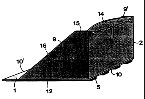
Reference is now made to figures 4 to 6, which in
combination with figure 1 illustrate a first, shovel-like
embodiment of the damming device according to the invention. In
this case, those devices that have the purpose of holding the
damming board 2 in an upright position, consist of two tensile
force carrying connection devices which extend between the wet
side of the damming board and the anchoring board 1. More pre-
cisely, these connection devices consist of end surfaces 9, 9'
which extend along the two opposite, transversal edges of the
board 1 and the two opposite, up-right edges of the damming
board 2. The boards 1, 2 are interconnected in a liquid-proof
way along the connection line 10 which extends along the lower
edge of the damming board and the top side of the anchoring
board. A liquid-proof connection also exists along the lines
11, 12 which connect the individual end surface to the damming
board 2 and the anchoring board 1, respectively. In practice
the boards 1 and 2 as well as the end surfaces 9, 9' may be
made of plates which are united to each other by means of weld-
ing. In this context, however, it should be pointed out that
the end surfaces 9, 9' also may be made of an elastically
CA 02288838 1999-11-04
WO 98/51865 PCT/SE98/00547
6
flexible material. However, in practice it is preferred to make
the individual end surface of a shape-stiff material like the
damming and anchoring boards and to stiffly unite the end sur-
face with these boards while forming a construction which is
shovel-like and which, in an active state, opens towards the
flood side.
For forming a continuous protective bank of the type
shown in figures 5 and 6, a plurality of such, shovel-like dam-
ming devices are placed side-by-side adjacent to each other. In
order to achieve sealing of adjacent damming devices in the
assembled protective bank, advantageously cross-section-wisely
substantially U-shaped sealing strips 13 (or bands) are arran-
ged, which are applied on the free edges of adjacent end sur-
faces in order to bridge possible spaces therebetween.
In order to facilitate erection of damming devices on
uneven grounds of the type which is indicated in figure 5, the
damming board 2 may in a flat, tension-free state have oblique
edges which mutually diverge in the direction upwards. By the
connection thereof to the end surfaces 9, these edges also keep
the end surfaces in a state diverging from each other in the
direction upwards, which allows several damming devices to be
tiled in each other. A loading or tightening mechanism gene-
rally designated 14 extends between the side edges of the dam-
ming board 2 which has the purpose of, when required, reducing
the distance between the upper parts of the side edges and
thereby those of the end surfaces, more precisely by bringing
the damming board 2 to sag in the direction towards the flood
side, as is apparent from figure 4. Suppose that the angle bet-
ween the individual end surface and the appurtenant anchoring
board should be variable within the range of 88 - 92° in order
to enable obliquity of the anchoring board of an adjacent
device within the range of +2° to -2° relative to the horizon-
tal plane. In this case the device may be made with end sur-
faces, each one of which having an angle of, for instance, 93°
relative to the anchoring board. When such a prefabricated
device has been put in place, the desired angle of inclination
may be achieved by reducing the length of the loading mechanism
14, the damming board 2 in the area of the upper edge thereof
sagging in the direction inwards towards the flood side. This
1 _ _-__.____ t
CA 02288838 1999-11-04
WO 98/51865 PCT/SE98/00547
7
not only leads to the advantage that the bottom of the ready-
made protective bank may be adjusted to uneven ground but also
that the damming board receives a better geometry force carry-
ing-wise than if it were plane.
In other respects, it may be mentioned that the end
surfaces 9, 9' in the shown embodiment have been formed with an
upper edge 15 which is horizontal as well as an edge 16 leaning
downwardly therefrom which ends at a distance from the rear
edge 10' of the board 1. By the fact that the end surfaces are,
in this manner, terminated at a certain distance from the edge
10', room is given for the above-mentioned sealing fabric or
band 8, whereby this band may simultaneously cover several
sealing devices subsequently following each other ir~ the ready-
made protective bank. In order to decrease the effect of possi-
ble waves and/or streams in the dammed water mass, the devices
should, when required, be able to be provided with particular
boards (not shown) which rest against or are connected to the
leaning edge portions of the end surfaces 9, 9'. Such an addi-
tional board may be made either with the same axial extension
as the individual damming device or be longer so as to cover
several devices positioned adjacent to each other. However, the
additional boards have to allow water to pass into and out of
the space between the end surfaces, preferably through a gap
between the lower edge of the additional board and the anchor-
ing board 1.
In case a protective bank needs to be erected with
angles between different sections, particular damming devices
may be used, the bottom boards of which having non-parallel
cross edges 12. With four perpendicular corner devices and a
number of standard devices even a temporary pool may be created
on the desired surface.
Reference is now made to figures 7 and 8 which in
combination with figure 2 show a second, alternative embodiment
of the invention. In this case, the devices which have the pur-
pose of holding the damming board 1 in place in an upright
position consist of one or more compressive force carrying sup-
port devices 17 arranged to act between the dry side of the
damming board 2 and a portion 1' protruding from the damming
board of the anchoring board 1. In practice, these support
CA 02288838 1999-11-04
WO 98/51865 PCT/SE98/00547
8
devices may advantageously consist of up-right boards which in
an active state protrude at an angle, for instance a perpen-
dicular angle, from the dry side of the damming boards 2 and
upwards from the top side of the protruding board pcrtion 1'.
Although the support boards 17 may be firmly connected to at
least one of the boards 1, 2, they may also be flexibly con-
nected to one of the boards, for instance via hinges which per-
mit folding of the boards, for instance towards the dry side of
the damming board in order to reduce the space of the support
boards in conjunction with storage and transportation. Instead
of boards, thin leas or bars which carry compressive force in
the area between the dry side of the damming board and the
board portion 1' may also be used.
As may be seen in figure 8, the spaces or openings
which arise between. adjacent damming devices in a continuous
protective bank may be sealed by means of a separate sealing
member 18, for instance a strip or fabric, an angled plate or
the like. By the fact that the sealing member partly has an air
gap on the bcttom side thereof it will be held urged in the
desired position by the water pressure acting from above. The
member is made sufficiently stiff so as to be able to bridge
also wider openings. In case the member is made of a stiff
material; it may advantageously have sealing fillets along its
long sides or foam rubber on its bottom side. As an additional
security, in particular at low water levels, the sealing member
may also be fixed in a mechanical way, for instance be clamped
by a resilient holder, be fitted below hooks, etc.
In figure 8 the joint being furthest to the left is
shown between adjacent damming devices situated above a hallow
in the ground, while the next opening is above a ridge. The
opening between adjacent anchoring boards is in both cases
equally wide, but the opening between the damming boards will
in one of the cases diverge and in the other case converge. The
three damming devices shown furthest to the right in figure 8
stand on plane ground, but are angled in relation to each other
in the ground plane, the two joints between the damming boards
narrowing wedge-shapedly in opposite directions. Thus, the
width of the openings between anchoring boards varies here,
_T -__ _____._. __~ _._ T
CA 02288838 1999-11-04
WO 98/51865 PCT/SE98/00547
9
while the openings between adjacent damming boards become par-
allel.
Reference is now made to figures 9-11 which in combi-
nation with figure 3 show a third embodiment of the damming
device according the invention. In this case, the tensile force
carrying connection device between the boards 1, 2 consists of
a long narrow element 19 which at one end is attached to the
wet side of the damming board, more precisely at a distance
from the lower edge of this board, and at an opposite end is
attached to the anchoring board, more precisely at a distance
from the damming board. In practice, the connection element 19
may consist of a wire, rod or the like, which is coupled to
suitable fastenings. In this embodiment, the boards 1, 2 con-
stitute separate components which may be interconnected when
the need arises, i.e. when a protective bank is to be erected
and the two boards are to fulfil their purposes. Although con-
nection of the two boards may be realised in many different
ways, figures 9 and 10 show how the anchoring board 1 in the
area of its dry side has a groove 20 in which the lower edge 21
of the damming board 2 may be applied. In other words, the
lower edge 21 of the damming board forms a male-like element
and the groove 20 a seat for this male element. A continuous,
liquid-proof fabric 22 is applied against and fixed to the
inside of the damming board 2 and the top side of the anchoring
board 1, a flexible portion of the fabric extending between the
separated boards. When the boards are mounted together, this
fabric folds in the transition between the boards without loos-
ing its liquid-sealing ability.
As may be seen in figure 11, the fabric 22 may advan-
tageously be common for adjacent damming devices in the form of
boards 1, 2 co-acting in pairs. Thus, in the boundary zone bet-
ween two adjacent damming devices, a flexible fabric portion
22' will extend admitting a certain mobility between the dif-
ferent boards. Along the long side edge of the ready-made
erected protective bank, which is directed towards the flood
side, the fabric 22 has a larger width than the anchoring
boards 1, a projecting portion of the fabric sealing against
water leakage under the anchoring board.
CA 02288838 1999-11-04
WO 98/51865 10 PCT/SE98/00547
In figure 12 ar~ additional embodiment is shown accor-
ding to which a number of tensile force carrying connection
devices between the damming board 2 and the anchoring board 1
consist of beads generally designated 23. Each such bead 23 is
formed as a continuous and cross-section-wise arched member
composed of a board portion 24 outwardly cambered inwards from
the damming board 2 as well as a board portion 25 outwardly
cambered upwards from the anchoring board 1. In practice, the
arched board portion 24 may extend along the major part of the
i0 height of the damming board 2 (or even the entire height) at
the same time as the corresponding board portion 25 of anchor-
ing board 1 extends along the major part of the width thereof.
The board portion 24 narrows in the direction towards the upper
end 24' thereof. In an analogous way, the board portion 25 nar-
rows in the direction towards an end portion 25' which is dis-
tanced frcm the damming board 2. The narrowing shape of each
board portion respectively is made along the side extension as
well the down extension. By the fact that the vertical and
horizontal board portions of the bead narrow, several damming
devices may be tiled in each other.
In the example according to figure 12, the damming
device includes four mutually parallel beads 23. The free ends
of the board portions 25 which are included in said beads mouth
in a common collection chanr_el 26 which is delimited by a board
portion designated 27 which extends axially between the two
opposite side edges of the anchoring board 1. Most suitably the
channel 26 extends parallel to the damming board 2. Adjacent to
the channel-limiting board portion 27 a fabric or skirt 28 is
arranged which, as previously described, forms a sealing
against-the ground. In case water would leak in under the skirt
28 and the rear, plane portion of the board 1, the water will
be distributed via the channel 26 to one or more of the chan-
nels which are defined by the arched beads and drained out on
the dry side of the damming device. In other words, the arched
beads 23 constitute not only tensile force carrying connection
devices between the two boards 1 and 2, but also a draining
means.
_T _. __.. _.
CA 02288838 1999-11-04
WO 98/51865 PCT/SE98/00547
11
Feasible Modifications of the Invention
The invention is not solely restricted to the embodi-
ments described above and shown in the drawings. Thus, only
one, suitably centrally located, stiff or flexible device hav-
ing a large surface extension may be used as tensile force car-
rying device instead of two (stiff or flexible) end surfaces at
opposite cross edges. Furthermore, it is conceivable to make
the shovel-like embodiment according to figures 4-6 in such a
way that the boards and end surfaces respectively may be folded
in relation to each other so as to facilitate storing and
transportation.