Note: Descriptions are shown in the official language in which they were submitted.
CA 02289187 1999-11-09
-r. Robert E. Myer 64
r
PILOT SIGNAL DETECTION SYSTEM USING BAND REJECT FILTER
BACKGROUND OF THE INVENTION
1. Field of The Invention
This invention relates to amplifiers and, more particularly, to a feed forward
distortion reduction system using a band reject filter.
2. Description of Related Art
Amplifiers often add undesired distortion to a signal, creating an output
signal
1 o comprising distortion or nonlinear components and the signal component.
The
distortion includes any undesired signals added to or affecting adversely the
input
signal. There is therefore a need to devise techniques that can eliminate
substantially
or reduce significantly the distortion produced by the amplifier.
Feed-forward correction is routinely deployed in modern amplifiers to
15 improve amplifier linearity with various input patterns. The essence of the
feed-
forward correction is to manipulate distortion, such as intermodulation (IMD)
components, created by the amplifier so that at the final summing point, the
distortion
cancels out. Due to the unpredictability of input RF carrier pattern as well
as the
resultant distortion location, a known frequency component, i.e. a pilot
signal, is
2o injected in the main signal path with the distortion produced by the
amplification
process. In feed-forward amplifiers, the feed forward distortion reduction
circuitry
minimizes the pilot signal along with the distortion. As such, by designing
the feed
forward distortion reduction circuitry to detect and cancel the pilot signal,
the
distortion can also be removed.
25 The pilot signal is an electrical signal comprising at least one frequency
component spectrally located near the frequency band of operation of the
electrical
circuit. A more complete description of the pilot signal is shown in FIG. 1
which
shows the frequency response of a radio frequency (RF) amplifier including the
location of the pilot signal. The pilot signal can be near the lower edge of
the
30 operating band (e.g., pilot 1) and/or located near the upper edge of the
band of
CA 02289187 1999-11-09
Robert E. Myer 64 2
operation (e.g., pilot 2). The pilot is positioned a spectral distance of ~ f
from an
edge of the band of operation whose center frequency is fo . The electrical
characteristics (e.g., amplitude, phase response, spectral content) of the
pilot signal
are known. It should be noted that although the pilot signal is shown as
having one or
two spectral components of a certain amplitude, the pilot signal can comprise
a
plurality of spectral components having various amplitudes.
The feed forward distortion reduction circuitry reduces distortion produced by
the RF amplifier by applying the pilot signal to the RF amplifier and making
adjustments based on information obtained from the applied pilot signal. FIG.
2
1o discloses feed-forward correction circuitry 10 and its use of information
obtained
from the pilot signal to reduce distortion produced by RF amplifier 12. An
input
signal, for example including at least one carrier signal, is applied to a
splitter 14.
The splitter 14 replicates the input signal on a main signal path 16 and a
feed forward
path 18. The splitter 14 is part of a feed forward loop referred to as loop #
l, which in
15 addition to the splitter 14, comprises gain & phase circuit 20, coupler 22,
the RF
amplifier 12, delay circuit 24 and couplers 26 and 28. The signal on the main
path 16
is applied to gain & phase circuit 20. The output of gain & phase circuit 20
and the
pilot signal are applied to the coupler 22. Typically, the amplitude of the
pilot signal
is much less (e.g., 30 dB less) than the amplitude of the input signal so as
not to
2o interfere with the operation of the amplifier 12. The output of coupler 22
is applied to
the amplifier 12 whose output comprises the amplified input signal, the
amplified
pilot signal and distortion signals produced by the amplifier 12. A portion of
the
output of the amplifier 12 is obtained from the coupler 26 and is combined at
the
coupler 28 via coupling path 30 with a delayed version of the input signal on
the feed
25 forward path 18 to isolate the pilot signal with distortion on the feed
forward path 18.
The input signal on the feed forward path 18 is sufficiently delayed by delay
circuit
24 so that such signal experiences the same delay as the signal appearing at
the
coupler 28 via the path 30.
The gain & phase circuit 20 is controlled via control path 32 with control
3o signals to adjust the gain and/or phase of the signal such that the signal
appearing at
CA 02289187 1999-11-09
Robert E. Myer 64
the coupler 28 via the path 30 is substantially the inverse (equal in
amplitude but
180°out of phase) of the delayed input signal at the coupler 28. The
control signals)
appearing on the control path 32 of the gain & phase circuit 20 is derived
from the
signal at the output of the coupler 28 in a well known manner using a
detection circuit
33. The detection circuit 33 can include a log detector connected to a nulling
circuit.
As such, the amplitude of the input signal, such as a carrier signal, is
detected, and the
nulling circuit attempts to reduce the amplitude of the carrier signal by
providing the
control signals on the control path 32. Alternative detection circuits can
detect well
known electrical signal characteristics such as amplitude, phase, and/or
frequency of
1o the signal. The input signals applied to the coupler 28 substantially
cancel each other
leaving at the output of the coupler 28 the pilot signal with distortion
produced by the
amplifier 12. Loop # 1 is thus a feed forward loop which serves to isolate on
the feed
forward path 18 the pilot signal with distortion produced by the amplifier 12.
The pilot signal with distortion at the output of the coupler 28 is fed to
gain &
t5 phase circuit 34 whose output is fed to amplifier 36 whose output is
applied to
coupler 38. A portion of the signals on the main signal path 16 (carrier
signal(s), pilot
signal with distortion) after the amplifier 12 is fed to a delay circuit 40
whose output
is fed to the coupler 38. T'he delay circuit 40 is designed such that signals
from the
output of the amplifier 12 applied to the coupler 38 experience substantially
the same
2o delay as the signals from the output of the amplifier 36 applied to the
coupler 38.
Because the frequency, amplitude and other electrical characteristics of the
pilot signal are known, pilot detect circuitry 42 can use detection circuits
such as a log
detector (or other well known detection circuits) to detect the amplitude of
the pilot
signal or a portion of the pilot signal via coupler 44 and a nulling circuit
to reduce the
25 amplitude of the pilot signal by providing control signals to the phase and
gain circuit
34. In general, the detection circuitry 42 will detect the pilot signal and
use this
information to generate control signals onto path 46 to cause the gain & phase
circuit
34 to modify the pilot signal on the feed forward path 18 such that the pilot
signal on
the main path 16 is substantially the inverse (equal in amplitude but
180° out of
3o phase) of the pilot signal on the feed forward path 18 at the coupler 38.
The
CA 02289187 1999-11-09
Robert E. Myer 64 4
corresponding pilot signals and distortion substantially cancel each other at
the
coupler 38 leaving the carrier signals) at the output of the system.
Therefore, loop #
2, which comprises the coupler 26, the coupler 28, the gain & phase circuit
34, the
amplifier 36, the coupler 38 and the delay circuit 40 is a feed forward loop
which
attempts to cancel the pilot signal to cancel substantially the distortion
produced by
the amplifier 12.
In actual systems, however, there is rarely an absolute cancellation of the
distortion and the pilot signals. This is at least partially explained by the
difficulty in
detecting the pilot signal after cancellation. The amplitude of the pilot
signal is
1 o typically relatively small at the output of the feed forward distortion
reduction system
because of the cancellation of the pilot and the relative amplitude of the
pilot signal
with respect to the amplitude of the in-band carrier signal(s). Thus, a need
exists for
pilot detection systems to improve the detection of the pilot signal. With
improved
pilot signal detection, improved reduction of the pilot signal can be
achieved,
15 resulting in improved distortion reduction.
SUMMARY OF THE INVENTION
The present invention involves a pilot signal detection system which uses a
band reject filter to reject the frequency band of at least one carrier signal
to improve
2o pilot signal detection. For example, in a feed forward distortion reduction
system, the
carrier signals) is on a main signal path along with a pilot signal which is
injected
into the main signal path at a frequency adjacent to the frequency band of the
carrier
signal(s). The carrier signals) and the pilot signal are amplified on the main
signal
path, resulting in distortion on the main signal path. To reduce the
distortion from the
2s main signal path, the feed forward distortion reduction system detects and
reduces the
pilot signal. To improve detection of the pilot signal, the pilot signal
detection system
provides a signal representative of the carrier signals) and the pilot signal
with
distortion from the main signal path onto a pilot detection path. A band
reject filter
on the pilot detection path rejects the frequency band of the carrier signals)
while
3o allowing the frequency of the pilot signal to pass through to pilot detect
circuitry.
CA 02289187 2002-12-12
Without the presence of the carrier signal(s), the pilot detect circuitry can
more
accurately detect the pilot signal on the pilot detection path. In response to
the
detected pilot signal, the pilot detect circuitry can provide control signals)
to
improve the reduction of the pilot signal by changing the relative phase
and/or gain
.°> between the signals on the main signal path and the feed forward
path. Thus, by
improving the detection of the pilot signal, the pilot detection system
improves the
reduction of the pilot signal and thereby of the distortion.
In accordance with one aspect of the present invention there is provided a
method of reducing a pilot signal on a main signal path parrying at least one
carrier
1G signal, said method comprising: providing to a pilot detection path a pilot
detection
signal representative of said at least one carrier signal and said pilot
signal on said
main signal path; rejecting from said pilot detection signal a frequency band
of said
at least one carrier signal while passing a frequency for said pilot signal;
and
detecting an amplitude for said pilot detection signal; and responding to said
15 amplitude of said pilot detection signal by providing at least one control
signal to
alter the amplitude of said pilot: signal on said main signal path.
In accordance with another aspect of the present invention there is provided a
distortion reduction system for reducing a pilot signal on a main signal path
for
carrying at least one carrier signal, said system comprising: a first
splitting device
20 on said main signal path provides a pilot detection signal representative
of said at
least one carrier signal and said pilot signal on said main signal path to a
pilot
detection path; a band reject filter on said pilot detection path receives
said pilot
detection signal and rejects from said pilot detection signal a frequency band
of sand
at least one carrier signal while passing a frequency for said pilot signal; a
signal
25 detector detects an amplitude of said pilot detection signal from said band
reject
filter; and control circuitry responsive t.o said amplitude of said pilot
detection signal
by providing at least one control signal to alter the amplitude of said pilot
signal on
said main signal path.
CA 02289187 2002-12-12
Sa
BRIEF DESCRIPTION OF THE DRAWINGS
Other aspects and advantages of the present invention may become apparent
upon reading the following detailed description and upon reference to the
drawings
in which:
FIG. 1 shows an example frequency response curve of an RF amplifier
showing the frequency within which the amplifier is operating;
FIG. 2 is a block diagram of a prior art feed forward distortion reduction
scheme used for RF amplifiers;
FIG. 3 shows a genera block diagram of a feed forward distortion reduction
system using gain and phase control according to the principles of the present
invention; and
FIG. 4 shows a graphical representation of the frequency response of a band
reject filter according to the principles of the present invention.
DETAILED DESCRIPTION
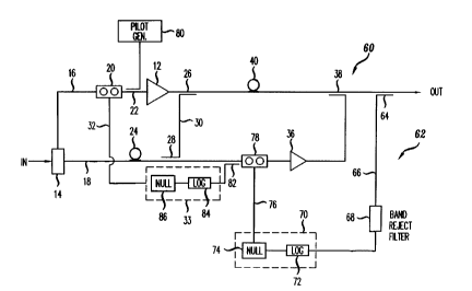
t 5 An illustrative embodiment of a pilot signal detection system according to
the principles of the present invention is described below in a feed forward
distortion
reduction system. FIG. 3 shows a general block diagram of a feed forward
distortion reduction system 60 which uses a pilot signal detection system 62
to
improve the detection of the pilot signal. In this embodiment, the pilot
signal
z0 detection system 62 includes a coupler 64 which provides a radio frequency
(RF)
representation of the amplified carrier signals) and the pilot signal from the
main
signal path I6 onto a
CA 02289187 1999-11-09
Robert E. Myer 64 6
pilot signal detection path 66. A band reject filter 68 rejects the frequency
band of
the carrier signals) but allows the pilot signals) to pass through to pilot
detect
circuitry 70. By rejecting the carrier signal(s), the band reject filter 68
improves pilot
signal detection by enabling the pilot detection circuitry 70 to detect a
wider range of
amplitudes for the pilot signals) because the carrier signals are not
interfering with
the pilot signal(s). It is desirable to locate the pilot as close as possible
to the carrier
frequency band, so that the pilot signal accurately reflects the amplifier
response to
the carrier frequencies. In doing so, however, the presence of the carrier
signals
hampers the ability to detect the lower amplitude reduced pilot signals. By
using the
1o band reject filter 68, the carrier signals are rejected from the pilot
signal detection
path 66, and the reduced pilot signal can be more accurately measured by the
pilot
detection circuitry 70.
The pilot detect circuitry 70 can include a log detector 72, which provides a
direct current (DC) signal representative of the amplitude of the pilot
signal, and a
t 5 nulling circuit 74 which attempts to reduce the amplitude of the pilot
signal by
providing gain and/or phase adjustments on the control line 76 to a gain and
phase
circuit 78 on the feed forward path 18. Because the band reject filter 68
enables more
of the amplitude of the pilot signal to be detected by pilot detect circuitry
70, the pilot
detection system 62 can provide gain and/or phase control signals to more
precisely
2o cancel the pilot signal at the coupler 38, thereby improving the
cancellation of the
distortion on the main signal path 16.
In operation, the feed forward distortion reduction system 60 receives the
signal S to be amplified, and the splitter 14 provides an analog
representation of the
signal S onto the main signal path 16 and the feed forward path 18. The signal
S on
25 the main signal path 16 is applied to the gain & phase circuit 20. The
output of gain
& phase circuit 20 is applied to the main leg of a coupler 22. A pilot signal
generator
80 generates a pilot signal and provides the pilot signal to a second leg of
the coupler
22 which injects the pilot signal into the main signal path. The pilot signal
can have
one or more spectral components or varying spectral components. In this
3o embodiment, the pilot generator 80 generates a pilot signal with spectral
components
CA 02289187 1999-11-09
Robert E. Myer 64 7
adjacent to and on either side of the Garner frequency band. For example, the
pilot
signal can be generated with spectral components at about 850 MHz and/or 920
MHz
with the Garner frequency band being at between 870 and 900 MHz. In this
embodiment, the pilot signals) will be about 30 dB below the Garner signal(s).
The pilot signal and the carrier signal on the main signal path 16 are applied
to
the amplifier 12 whose output comprises the amplified signal S, the amplified
pilot
signal P and distortion D produced by the amplifier 12. A portion of the
output S, P
and D of the amplifier 12 is placed on the coupling path 30 via the coupler 26
and
combined with a delayed version of the signal S on the feed forward path 18 to
isolate
to the pilot P with distortion D on the feed forward~path 18.
The gain & phase circuit 20 is controlled by a phase and gain controller 33 to
adjust the gain and phase of the Garner signal S on the main signal path 16
prior to the
amplifier 12 such that the amplified signal S, P with D at the coupler 28 is
substantially the inverse (equal in amplitude but 180°out of phase) of
the delayed
t5 signal S on the path 18. As such, the combining signals cancel to isolate
the pilot P
and distortion D on the feed forward path 18. The control signals) appearing
on the
control paths) 32 of the gain & phase circuit 20 can be derived from the
portion of
the amplified signal S, P and D on the coupling path 30 and the delayed
version of the
signal S on the path 18 andlor from the output of the coupler 28. In this
embodiment,
2o the gain controller 33 receives a signal representing the output of the
coupler 28 from
a coupler 82 to determine how well the cancellation of the carrier signal S
occurred at
the coupler 28. The gain and phase controller 33 can include a log detector
84,
which provides a direct current (DC) signal representative of the amplitude of
the
signal from the coupler 82, and a pulling circuit 84 which attempts to reduce
the
25 amplitude of the signal S by providing gain and/or phase adjustments on the
control
line 32 to the gain and phase circuit 20 on the main signal path 16. As the
cancellation of the combining signals S improves, the feed forward distortion
reduction improves the isolation of the pilot P and distortion D on the feed
forward
path 18.
CA 02289187 1999-11-09
Robert E. Myer 64 g
The isolated pilot P and distortion D on the feed forward path 18 are fed
forward to cancel with the pilot P and distortion D on the main signal path
16. In this
embodiment, the output of the coupler 82 is applied to the gain & phase
adjuster 78
which adjusts the pilot signal P and distortion D on the feed forward path 18
according to phase and gain control signals from the pilot detection circuit
70. The
output of gain and phase adjuster 78 is applied to the amplifier 36 whose
output
comprises the amplified pilot signal and distortion D. The amplified pilot
signal and
distortion D is output from the amplifier 36 provided to the coupler 38. The
coupler
38 destructively combines corresponding portions of the signals P and D from
the
to feed forward path with those on the main signal path 16 to produce at the
output of
the coupler 38, the amplified signal S with reduced pilot signal P and
distortion D.
To improve the reduction of the pilot signal P and thereby of the distortion
D,
a representation of the amplified signal S and reduced pilot signal P with
distortion D
is obtained from the output of the system 60 and placed on a pilot signal
detection
path 66 using the coupler 64. To improve the detection of the pilot signal on
the pilot
detection path 66, the band reject filter 68 is provided on the pilot
detection path 66.
FIG. 4 shows a graphical representation of the frequency response for the band
reject
filter 68 in an embodiment of the pilot detection system 62. As shown, pilot
signals
at 850 MHz and 920 MHz pass through the band reject filter 68 to the pilot
detection
2o circuitry 70, but the band reject filter rejects the in band carrier
signals, for example
between approximately 869 MHz and 894 MHz. Other frequency bands can be
rejected by the band reject filter 68, such as 1.9 - 2.0 gigahertz (GHz) or
2.1 - 2.2
GHz. The pilot detection circuitry can detect a wider range of amplitudes for
the
reduced pilot signals) because the Garner signals are not hampering or
interfering
2s with the detection of the pilot signal(s). By using the band reject filter
68, the carrier
signals are rejected from the pilot signal detection path 66, and the reduced
pilot
signal can be more accurately measured by the pilot detection circuitry 70.
For
example, in FIG. 4, the band reject filter 68 rejects the carrier signals) by
about 60dB
which improves the ability to detect the pilot signal(s).
CA 02289187 1999-11-09
Robert E. Myer 64 9
In this embodiment, the pilot detection circuitry 70 includes the log detector
72 which receives the reduced pilot signal on the pilot detection path 66 from
the
band reject filter 68. The log detector 72 produces a DC signal representative
of the
amplitude of the pilot signal on the path 66. A nulling circuit 74 receives
the signal
representative of the amplitude of the pilot signal and attempts to reduce the
amplitude of the amplitude signal from the log detector 72 by providing gain
and/or
phase control signals to adjust the relative phase and/or gain between the
signal
combining at the coupler 38. In this embodiment, the pilot detect circuitry 70
provides the gain and/or phase control signals to the gain and phase circuit
78 on the
1o feed forward path 18. As such, the pilot signal detection circuit 70
provides gain
and/or phase control signals to adjust the gain and /or phase adjustments
performed
on the pilot signal P and distortion D on the feed forward path 18 to improve
cancellation of the pilot signal P with the distortion D from the main signal
path 16 at
the coupler 38. By improving the detection of the pilot signal after
cancellation or
t5 reduction, the pilot detection system 62 can improve the reduction of the
pilot signal
and thereby of the distortion. In this embodiment, the pilot signal is reduced
to about
60dB in amplitude below the carrier signal(s).
In addition to the embodiment described above, alternative configurations of
the pilot signal detection system according to the principles of the present
invention
2o are possible which omit and/or add components and/or use variations or
portions of
the described system. Additionally, the embodiment of the pilot detection
system has
been described as being used with a particular feed-forward RF amplifier
arrangement, but the pilot detection system can be used to improve pilot
signal
detection in other amplifier or electrical circuit arrangements using a pilot
signal.
25 Additionally, the pilot detection system has been described as detecting
the pilot
signals) on both or either side of a carrier frequency band, but the pilot
detection
system can be used to detect a single, changing or multiple pilot signals, and
the pilot
signal can be positioned relative to a frequency band with multiple carriers
or the
frequency band of a single carrier whether outside or inside the frequency
band of the
30 multiple carriers. The pilot detection system has been described with a
band reject
CA 02289187 1999-11-09
Robert E. Myer 64 10
filter which rejects the frequency band of the carrier signals) and permits
adjacent
frequencies as shown in FIG. 4. Other filters with different responses are
possible
which reject the carrier frequencies while allowing the pilot signals) to
pass.
Furthermore, the pilot detection system has been described as detecting pilot
signal
amplitude, but other parameters or characteristics of the pilot signal can be
detected.
The system has been described as using couplers, but other devices, such as
3dB splitters and other coupling, signal splitting or sampling devices, can be
used as
well as other combining devices, such as summers. Depending on the
application, the
gain and/or phase circuitry can be positioned in different locations and/or
paths within
1 o the feed forward amplifier arrangement. The pilot detection system has
been further
described as using different configurations of discrete components, but it
should be
understood that the feed forward system and portions thereof can be
implemented in
application specific integrated circuits, software-driven processing
circuitry, firmware
or other arrangements of discrete components as would be understood by one of
ordinary skill in the art with the benefit of this disclosure. What has been
described is
merely illustrative of the application of the principles of the present
invention. Those
skilled in the art will readily recognize that these and various other
modifications,
arrangements and methods can be made to the present invention without strictly
following the exemplary applications illustrated and described herein and
without
2o departing from the spirit and scope of the present invention.