Note: Descriptions are shown in the official language in which they were submitted.
CA 02289265 1999-11-08
-1-
LINE SHUNT AND GROUND FAULT APPARATUS AND METHOD
Field of the Invention:
The invention pertains to diagnostic devices and methods for use
with communication links. More particularly, the invention pertains to such
devices and methods which can be used to determine the presence or absence of
shunt impedances as well as the presence or absence of ground faults on
communication links.
Background of the Invention:
Multiprocessor communication systems which provide bidirectional
communication capabilities for each of the processors using a bidirectional
communication link are known. Such systems are often associated with alarm or
monitoring functions.
One known form of such a system incorporates a common control
unit which is connected to a two-wire electrical cable which extends
throughout a
region to be monitored. A plurality of detectors can be coupled across the
wires
of the link at locations corresponding to portions of the region to be
monitored.
Additionally, output devices can also be coupled across the wires of the link
and
can be used to provide various output functions such as energizing or de-
energizing
solenoids or energizing or de-energizing audible or visual annunciators.
It has also been recognized that such communication links at times
exhibit deteriorating performance due to shunt impedances or ground faults.
While
there have been approaches developed in the past which attempt to establish
the
location of one or more such conditions on Class A loops, it would be
desirable to
ascertain the existence of shunt impedances across the wires of the link or
the
location of ground faults in other link configurations. Preferably, it would
be
desirable to provide such functionality without having to substantially
increase the
base cost of such systems for a given number of detectors. Additionally, it
would
be preferred if the desired functionality can be provided without
substantially
increasing system complexity.
CA 02289265 1999-11-08
-2-
Summary of the Invention:
A multi-processor communication system, in one aspect, includes a
common communication link which could be implemented as a two-wire cable.
Coupled to the link are the members of a plurality of electrical devices some
of
which might be substantially identical.
Typical electrical devices would include ambient condition detectors
such as smoke detectors, position detectors, motion detectors, gas detectors,
humidity detectors, and the like. Other types of electrical devices could be
used
for energizing or de-energizing solenoids so as to implement output functions
which
could include locking or unlocking, opening or closing doors or windows,
energizing or enabling audible or visible output devices of various types to
convey
messages, warnings or the like. In another aspect, the detectors can be
clustered
on one communication link, and some of the output devices, if desired,
clustered
on another communications link.
The electrical devices can each include a local control circuit, which
could be implemented as a programmed processor, and associated instructions.
In
one aspect, the local control circuit is coupled to a solid state or
mechanical switch
which can be used to open circuit the communication link in the vicinity of
the
electrical unit. A common control unit, if present, can in turn include
similar solid
state or mechanical switches which under the control of electrical circuitry
therein
can isolate the communication link from that control unit.
In order to measure the shunt resistance of the communication line,
the devices contain drive circuitry to drive a current across the two wires of
the
communication line. The current is driven in a manner that the devices
connected
across the wires will not interfere with the measurement of the shunt
resistance
across the two wires.
The devices measure the voltage drop produced across the wires by
the current and determine if the line shunt resistance is greater than a
predetermined value. If the shunt resistance is lower than the predetermined
value,
a trouble indication can be generated.
CA 02289265 1999-11-08
-3-
In a preferred aspect, the current is driven in a polarity opposite to
the polarity present when delivering power to the devices. In this manner,
each
device appears to be an open circuit or at least a very large impedance when
the
polarity is reversed. The voltage developed across the line will then be
determined
by the line shunt resistance.
In another aspect, the current can be driven with the same polarity
as the polarity present when delivering power to the devices. However, in this
case, it would be driven at very low value such that the voltage developed
across
the wires of the communication link is less than the voltage value required to
deliver power to the devices. Since the devices do not have sufficient voltage
to
draw power from the line, the voltage on the line will be determined by the
line
shunt resistance.
In a preferred apparatus, each device also contains an isolation
circuit such that it can open circuit the link. The isolation circuit can be
implemented using solid state semiconductor switches.
Since each device open circuits the link, each device only checks the
portion of the link between itself and an adjacent device. If a shunt
resistance
across the two wires of the communication link is less than a predetermined
value,
a trouble indicator can be generated and the device address indicates the
location
of the shunt resistance. A voltage drive could be substituted for a current
drive
since these parameters are related.
When a low shunt resistance has been indicated, the device can be
commanded to open circuit the link to isolate the section of the communication
link
that has a low shunt resistance. This will prevent it from adversely affecting
the
communication process.
In many systems, the communication link is not connected to the
earth ground or external shielding around the link. A resistive leakage path,
or
ground fault, can occur from either or both wires of the communication link to
earth ground. This may potentially cause communication problems. It would be
desirable to be able to identify that this leakage resistance to earth ground,
or
ground fault, exists prior to encountering communications problems.
CA 02289265 1999-11-08
-4-
A preferred method includes checking to determine if a link exhibits
a ground fault. In one embodiment, the communication link includes two
conductors.
One conductor is connected to all devices and cannot be open
circuited by the devices. Each device has a capability to open circuit the
second
conductor.
To test the link, the devices open circuit the second conductor at
spaced apart locations on the link. When a respective device is between the
ground
fault and a predetermined unit, the ground fault will disappear relative to
the
predetermined unit.
When the ground fault is between the unit and the device, the ground
fault will be detected by the unit. By determining which device is closest to
the
ground fault and still between the ground fault and the unit, the location of
the
ground fault can be determined.
The predetermined unit can correspond to another device.
Alternately, if the system includes a common control unit, coupled to the
link, to
implement various system-wide communication functions, the predetermined unit
can correspond to the common control unit.
A predetermined searching pattern can be used to determine the
location of the ground fault. A binary search pattern will find the ground
fault
with the least number of steps.
One method of locating a ground fault to one of the conductors of
a communication link includes selecting an initial location on the link. Where
the
initial location corresponds to an end of the link, another displaced location
on the
link is selected. The link is open circuited at the another location.
Each of the segments can then be tested by use of voltage-type test
signals to determine which segment includes the fault. Relative of this
segment
which indicates or includes a fault, another displaced location is selected
and the
line is open circuited. Each of the shortened line segments is then tested to
determine which segment includes the fault. As noted above, a binary search
CA 02289265 1999-11-08
-5-
pattern can be used and will determine the location of the fault in a minimal
number of steps.
In yet another aspect, the isolation switches of each of the electrical
units can be opened. An attempt can then be made to cause a test current to
flow
between an earth ground and the common conductor of the communication slink
which is not open circuited. The presence of this test current can be detected
using
a ground fault detect circuit coupled between the earth ground and the
continuous
conductor of the communications link. The current can be applied by either the
electrical units, acting in parallel, or from another source such as the
ground fault
detect circuit or a supply elsewhere in a common control unit coupled to ends
of
the communication link.
In either instance, the presence of a ground fault between the open
circuited conductor of the link and the earth ground can be detected by one or
more
adjacent electrical devices. Non-adjacent electrical devices are isolated from
the
ground fault due to the open circuited isolation switches of the adjacent
electrical
devices. Hence, the location of the ground fault can be undetermined, between
two
adjacent electrical devices. In that instance, the ground fault can be
isolated from
the communication link by maintaining the isolation switches of the two
adjacent
electrical devices in their respective open circuit states and short-
circuiting the
isolation switches of the remaining electrical units thereby enabling normal
communication to re-initiated.
Numerous other advantages and features of the present invention will
become readily apparent from the following detailed description of the
invention
and the embodiments thereof, from the claims and from the accompanying
drawings.
Brief Description of the Drawings:
Fig. 1 is a block diagram of a communication system in accordance
with the present invention;
Fig. 2 is a block diagram of a portion of the communication link of
Fig. 1 illustrating additional details of electrical units coupled thereto and
circuitry
for locating the presence of a shunt resistance;
CA 02289265 1999-11-08
-6-
Fig. 3 is a block diagram of a portion of an alternate form of the
system of Fig. 1 configured so as to locate a detected ground fault;
Fig. 4 is a block diagram of a portion of another form of the system
of Fig. 1 configured to carry out an alternate form of ground fault locating;
and
Fig. 5 is a block diagram of yet another form of the system of Fig.
1 which can be used to locate a ground fault.
Detailed Description of the Preferred Embodiments:
While this invention is susceptible of embodiment in many different
forms, there are shown in the drawing and will be described herein in detail
specific embodiments thereof with the understanding that the present
disclosure is
to be considered as an exemplification of the principles of the invention and
is not
intended to limit the invention to the specific embodiments illustrated.
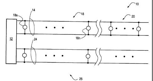
Fig. 1 illustrates a multi-processor communications system 10 which
can be used for monitoring a plurality of conditions in one or more regions to
be
supervised. As illustrated, the system 10 includes a common control unit 12
which
could be implemented as one or more interconnected programmed processors and
associated, prestored instructions.
The unit 12 incudes an interface for coupling, for example, to a
communications medium 14, illustrated in Fig. 1 for exemplary purposes only as
an optical or electrical cable.
Coupled to medium 14 is a plurality of ambient condition detectors
18 and a plurality of control or function units 20. It will be understood that
the
arrangement of the members of the pluralities 18 and 20 relative to the medium
14
is not a limitation of the present invention. The members of the plurality 18
can
include intrusion sensors,position sensors, gas sensors, fire sensors such as
smoke
sensors, thermal sensors or the like, all without limitation. The members of
the
plurality 20 can include solenoid actuated control or function implementing
units,
display devices, printers or the like.
Also coupled to the control unit 12 via a medium 24, illustrated for
example as a pair of electrical cables, is a plurality 26 of output devices.
These
could include audible or visible output devices without limitation, speech
output
CA 02289265 1999-11-08
-7-
devices and the like. The devices 26 are intended to broadcast a message,
which
might indicate alarm condition, in one or more predetermined regions.
It will be understood that the purpose for which the system 10 is
being used is not a limitation of the present invention. The invention can be
incorporated into local area networks which, for example, only transfer
information
between various devices coupled thereto. The invention can also be
incorporated
into peer-to-peer type communications systems which do not incorporate an
element
that corresponds to the common control unit 12 without departing from the
spirit
and scope of the present invention.
Figure 2 illustrates a system and method for locating a shunt
resistance. Three devices 18a, b, c and the control unit 12 are illustrated.
The
following comments also apply to members of the plurality 20, 26.
Each device, such as 18a, includes an isolator switch SWa. Each
of the devices 18a, b ... n, 20a, b ... n, 20a ... 20m includes a control
element
which can be implemented, at least in part as a programmed processor P-18a,-
18b
... 18n and P-20a,-20b ...-20m and associated instructions. Alternately, the
members of the pluralities 18, 20, 26 can be implemented using various forms
of
hardwired logic.
The processors each include output control ports or drivers A,, A2
and analog input port A3. The analog receiver A3 includes an A/D converter.
Alternately, the A/D converter can be a separate circuit external to the
respective
processor. The converter is used to detect a threshold value. The drivers (Al,
A2) could be a single drive pin from the respective processor or the output of
an
external drive circuit.
Each of the devices 18a ... 20m includes a local power supply such
as INTa, INTh .... Each local supply can receive electrical energy from link
14.
Alternately, each such supply can receive energy from another source such as a
battery.
During the shunt test, all switches SW12-a, SW12-b, SWa .. SWn
are opened. The conductor 14a is thus open circuited at each device, including
at
the control unit 12.
CA 02289265 1999-11-08
-8-
Next, the drive circuits (Al, A2) are turned ON so that a current
(Il, 12, 13) flows to the conductor 14b. Current 11 has no return path to the
internal ground of device 18a. Hence, the conductor 14b is driven to a high
positive voltage relative to that device's internal ground. This voltage is
measured
at input port A3.
If there is no shunt, all devices will produce a high positive voltage
relative to their internal grounds. This indicates that there is no shunt
resistance
present across the link 14.
On the other hand, if there is a shunt resistance at L to L' between
device 18b and device 18c, then there will be a return path for the 12 and 13
currents to return to their respective internal grounds through Q2 and Ql
respectively of these devices. The amplitude of voltage developed across the
link
14 (across the shunt resistance) is then a function of the internal resistance
R in the
current path in each device. [V(common) - V(+)] = [VINTi - V(Dl) - V(D3) -
V(Ql)]*(shunt resistance)/(R/2 + shunt resistance).
The value of R is divided in two because device 18b is in parallel
with device 18c so that R values are effectively in parallel. If the voltage
developed across the link 14 is lower than a predetermined value, then the
devices
will recognize that a shunt resistance is present with a value that is lower
than a
predetermined value. A trouble indication can be generated. The devices may
then leave their respective isolator switch, SWa, SWb ..., open to prevent the
shunt
impedance from affecting communications on the two conductors 14a, b.
All devices that do not detect a low shunt resistance, will close or
short circuit their respective isolator switch. This will restore the
connection of the
conductor 14a to the other devices. Likewise, the control unit 12 will close
SW12-
a, -b and restore power delivery and communication to the link 14. Only
switches
SWb, SWc will stay open.
In many cases, a second pair of wires is connected from the last
device, such as 20m, back to the control unit 12 so that power and
communications
can then reach device 18c. All devices will then receive power to continue
normal
CA 02289265 1999-11-08
-9-
operation. However, the shunt resistance from L to L' is isolated from the
communication line.
Fig. 3 illustrates a system 10-1 for detecting the location of a ground
fault. Common components of system 10-1 have been assigned the same.
identification numerals as in Fig. 2. In Fig. 3, processors P-18a' ... P-18n'
could
be implemented using processors P-18a ... P-18n as previously discussed
relative
to Fig. 2 but with expanded or additional instructions to carry out a ground
fault
test function.
In the system 10-1 control unit 12' includes control switches SW12'-
a and SW12'-b. These switches, could be implemented as field-effect
transistors,
bipolar transistors or any other type of controllable solid state or
mechanical
switch. The same comments apply to switches SWa, SWb, SWc ....
Switches 12'-a, 12'-b open circuit respective conductors 14a, b.
Unit 12' also incudes ground fault detect circuitry 12'-1. The structure and
operation of circuitry 12'-l, which could be implemented in part with pre-
programmed instructions used to control one or more processors in unit 12',
are
discussed below.
One ground fault locating method involves starting at the unit 12'
and progressing out therefrom one device at a time. The steps include opening
and
closing the respective isolator switches SWa, SWb, SWC .... and, therefore,
open
circuiting and short circuiting the conductors 14a at each device, until the
ground
fault no longer disappears during the time when the device open circuits the
conductor 14a. This identifies the device closest to the ground fault which is
still
between the ground fault and the control unit 12. If the ground fault is after
the
first device, then only two checks are needed. If the ground fault is after
500
devices, 501 checks will be needed. This method can be used with T-taps on the
communication link.
In another method, the devices can be configured to drive a current
into the earth ground. The location of the earth ground shunt resistance
(ground
fault) at L to L' can be determined.
CA 02289265 1999-11-08
-10-
During this test SW12-a is opened and SW12b is closed in the
control unit 12. The isolation switch SWi in each device open circuits the
conductor 14a at each device. Then, each device drives a current (I1, 12, 13)
into
the conductor 14b which can then flow to the control unit(I) and out to the
earth
ground (I'). If there is no earth ground shunt resistance, then I' = 0 and
therefore
I1=0, 12=0, and 13=0.
On the other hand, if there is an earth ground shunt resistance at L
to L', then current can flow through the earth ground shunt resistance to
complete
the current path back to devices adjacent to point L. In this case, I' = 12 +
13,
I1=0 because the isolator SWb in device 18b' prevents formation of a complete
path back to device 18a'.
Devices 18b' and 18c' both sense that a current is flowing internally
and set an earth ground fault indicator or trouble signal. This trouble signal
can
then be transmitted to the control unit 12' or some other device for
indication and
display. Since both device 18b' and device 18c' indicate a ground fault, then
the
earth ground shunt resistance L to L' is determined to be between device 18b'
and
device 18c'.
In another system 10-2 and method illustrated in Fig. 4, a ground
fault circuit 12'-2 is connected between the control unit 12' and earth
ground. The
ground fault circuit 12'-2 applies a voltage V' to earth ground. This voltage
(V')
may be applied continuously as a pulse or in some other form, including
modulated
signals.
If a ground fault is present, then, a current (I') will flow into the
earth ground connections. The ground fault location check is made when the
isolator switches SWa, SWb ... are opened.
When the isolator switches SWa, SWb ... are open, current I' will
then flow through the shunt resistance, L to L', and create a voltage at the
input
circuits B2 of device 2 and B1 of device 3. The current will flow through the
devices to the conductor 14b and return to the control unit 12' and the ground
fault
circuit 12'-1.
CA 02289265 1999-11-08
-11-
Device 18a will not see any voltage at its input because the isolators
prevent any currents from flowing to the conductor 14a coupled to device 18a".
Devices 18b" and 18c" then will report that they received ground fault
signals.
This will determine the location of the ground fault.
If there are isolators in the negative wire and not in the positive
wire, then the same principles apply. The ground fault circuit can apply a
voltage
(V') and a detection means in the devices senses a voltage developed by the
devices
adjacent to the shunt resistance. A negative V' can be applied and the devices
sense a voltage at the inputs B 1 or B2.
Two isolators can be used with each device if they have diodes
across each of them so that current can flow in one direction as shown in Fig.
5.
The basic concept is that the isolators prevent other devices from detecting a
ground fault signal.
Only the device(s) adjacent to the shunt resistance connection detect
the ground fault signal. If there are isolators in the negative wire and not
in the
positive wire, then the same principles apply. The ground fault circuit can
apply
a voltage (V') and a detection means in the devices senses a voltage developed
by
the devices adjacent to the shunt resistance. A negative V' can be applied and
the
devices sense a voltage at the input B.
Other equivalent sensing means can be used such that only the
devices adjacent to the shunt resistance detect the ground fault circuit
signals when
the isolators are open. Other than a pulse, modulated waveforms or other
signals
can be applied to the earth ground. Either a positive or negative voltage (V')
can
be used, depending upon the type and polarity of the input circuit in the
devices).
From the foregoing, it will be observed that numerous variations and
modifications may be effected without departing from the spirit and scope of
the
invention. It is to be understood that no limitation with respect to the
specific
apparatus illustrated herein is intended or should be inferred. It is, of
course,
intended to cover by the appended claims all such modifications as fall within
the
scope of the claims.