Note: Descriptions are shown in the official language in which they were submitted.
CA 02289291 1999-10-15
WO 98/46347 ' PC'T/I1S98i~77~9
~.. ...' .,
Description
Control System and Method for Controlling a Gas Generating System
Technical field
This invention is directed to the production of industrial gases, and
more particularly, to a system and method .for generating an industrial gas,
and to a control system and method for controlling the generation of the
industrial gas, from a hydrocarbon feed stock (fuel), in response to dynamic
load demands from a downstream process.
Background Of the Invention
Reaction apparatus for the production of industrial gases, such as
hydrogeri, are well know in the prior art. These fuel processing apparatus
employ steam reforming as the most common method for producing
hydrogen from hydrocarbon fuels such as natural gas or naphtha.
Conventional commercial size fuel processing apparatus (reformers) are
typically very large constant output elements that are limited in their
ability
to adjust to variable demand or flow requirements.
Electric power generating devices known as fuel cell power plants are
electrochemical devices that operate by consuming hydrogen on an anode
electrode of their fuel cell stack assembly (CSA). The hydrogen demand of
the fuel cell power plant is variable and therefore not easily adaptable to
the
constant output characteristics of conventional commercial size reformers.
This led the assignee into the successful development of a compact reformer
and its associated technology. The compact reformer, operating as an
integral part of the power plant, is characterized by the ability to produce a
hydrogen rich stream that varies in response to changing power plant
hydrogen consumption. This technology is exemplified in assignee's US
sip
patents 4,098,858 and 4,098 589.
1
.-
CA 02289291 1999-10-15
WO 98/46347 PCT/US98/07739
It is also recognized that other industrial gas requirements exceed the
hydrogen purity levels typically produced by a fuel processing apparatus of
either the conventional commercial size designs or the compact reformer
designs used in fuel cell power plants. To meet such higher purity hydrogen
requirements, additional processing by secondary devices such as pressure
swing absorption (PSA), cryogenic or membrane elements can be used.
However, when this higher purity requirement is combined with variable
demand only a compact reformer of the type used in fuel cell power plants
has the inherent ability to meet this need. Unfortunately, it is not possible
to
directly couple a compact reformer to a secondary unit such as a PSA device
without making significant changes in the reformer unit's operational control
system.
A fuel cell power plant reformer seeks to supply hydrogen rich gas to
the CSA in response to hydrogen consumption which is proportional to the
fuel cell gross current or electrical load. The fuel cell power plant exhaust
gas (waste gas), depleted in hydrogen, is fed to the reformer burner to
provide heat for the steam reforming process. Reformer process fuel and
steam feed is adjusted in proportion to the fuel cell gross current, but with
the
requirement to also maintain a set reformer temperature.
For a fuel cell power plant operating at a steady point, constant
hydrogen consumption, the reformer temperature can be increased by
increasing the reformer fuel feed because it results in a direct and rapid
increase of the amount of exhaust gas fed to the reformer burner. This
means added energy input to the reformer and hence a rise in reformer
temperature. Conversely, a reduction in fuel feed at any steady operating
point means a drop in reformer temperature.
This direct link between reformer fuel feed and reformer heating in a
fuel cell power plant is not possible when a compact reformer is connected in
series to another hydrogen consumption or extraction process such as a
PSA unit. The PSA waste gas or blow down purge gas is used by the
reformer burner to heat the unit. However, the flow rate and heating value of
2
CA 02289291 1999-10-15
-3-
this waste gas depends on the specific operation of the PSA unit, but
there is no direct link between the fuel feed level to the reformer and
the quality or quantity of waste gas supplied back to the reformer
burner.
US-A-5,401,589 discloses a reformer apparatus for generating a
hydrogen-rich gas for consumption by a downstream fuel cell power
plant. The apparatus comprises a plurality of means for processing
incoming fuel to generate the hydrogen-rich gas using waist gas output
from the downstream process to provide energy for processing the fuel.
The apparatus further comprises a control means for . controlling the
amount of hydrogen-rich gas by bringing the respective processing
means into, or taking them out of, use via valuing arrangements in
response to variations in load demand.
24.06.99 16:20
..
CA 02289291 1999-10-15
WO 98146347 ~ : ; b~T/LTS98.'07739 .
ft9-~ifee~~,
There exists a need, therefore, for a system and method of gas
generation, and a temperature and flow control system and method therefor,
which accounts for the lack of.a direct link between feed gas and the waste
gas fed to reformer burners thereof from a down stream unit such as a PSA,
and which is applicable to multiple reformers joined together as a single
operating unit to provide increased capacity, wherein each unit requires its
own waste gas supply from the PSA and individual control of its temperature.
Disclosure of Invention
The primary object of this invention is to provide a control system and
method for controlling a gas generating system, responsive a to dynamic
load demand of a downstream process and which has a flexible operational
range.
And still another object of this invention is to provide a control system
for a fuel processing system and method which operates a plurality of
individual fuel processing systems as a single unit which is responsive both
efficiently and rapidly to'the dynamic load demands of a downstream
process.
The objects and advantages stated herein are achieved by the
control system and method of the present invention for controlling a fuel
processing system operational to produce a gas for a downstream process
from a fuel, wherein the fuel processing system uses a plurality of fuel
processing elements, a fuel input and a waste gas input, each of the fuel
processing elements having an individual output and the plurality of fuel
processing elements having a collective output, and wherein the
downstream process has a waste gas output and a dynamic gas load .
demand. .
3a
~_
CA 02289291 1999-10-15
WO 98/46347 PCTNS98/07739
The preferred embodiment of the control system includes a device for
receiving communication from the downstream process indicative of the
dynamic load demand and a device for controlling the collective output level
of the gas in response to the dynamic load demand. The device for
controlling is operative to substantially equally distribute the dynamic load
demand among the plurality of fuel processing elements such that the
individual outputs from each of the fuel processing elements are
substantially equal to each other for forming the collective output or most
efficiently distribute the dynamic load among the plurality of fuel processing
elements such that at least one of the individual outputs contributes to the
collective output.
The preferred embodiment of the method includes the steps of
receiving communication from the downstream process indicative of the load
demand and controlling the collective output level of the gas in response to
the communication. The step of controlling includes one of the steps of
substantially equally distributing the dynamic load demand among the
plurality of fuel processing elements such that the individual outputs from
each of the fuel processing elements are substantially equal to each other
for forming the collective output or most efficiently distributing the dynamic
load among the plurality of fuel processing elements such that at least one
of the individual outputs contributes to the collective output.
Brief Description of the' Drawings
FIG. 1 is a simplified schematic representation of the fuel processing
system of the present invention, including a control system therefor, which
includes a plurality of interfunctioning fuel processing elements;
FIG. 2 is a more detailed schematic representation of a single fuel
processing unit in accordance with the principles of the present invention
including the various inputs and outputs associated therewith, in
accordance with the principles of the present invention; and
4
CA 02289291 1999-10-15
WO 98/46347 PGT/US98/07739
FIG. 3 is a more detailed schematic view of the system shown in FIG.
1, including the various control elements of the system;
FIG. 4 is a schematic diagram indicative of the control scheme of the
present invention; _and
FIG. 5. is a simplified schematic view of a modular pallet design for
arranging the system of the present invention.
Best Mode for Carrying Out the Invention
Referring now to the drawings in detail, there is shown in FIG. 1, a
schematic representation of the fuel processing and control system of the
present invention, which is designated generally as 10. System 10 is shown
in use with a downstream gas consuming process 12 which has a dynamic
load demand signal LS to which system 10 is responsive. The downstream
process 12 may be any gas consuming process such as a cryogenic
process, a membrane process, a fueling station, a hydrogenation process, a
pressure swing adsorption process, etc. in general, system 10 functions to
sense the dynamic load of the downstream process 12 and processes fuel F
to produce the desired gas S for the downstream process, in an efficient,
maximized manner.
With reference to FIG. 1, system 10 uses a plurality of main
components including fuel processing elements 14. The number of fuel
processing elements shown in FIG. 3 is exemplary only and accordingly,
any number which are necessary to meet system and downstream process
requirements can be used. The system further includes a control system
16 for controlling the overall processing method and the various elements
used therein, a ventilation system 17, and various control elements 18,
discussed in greater detail below.
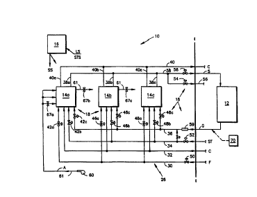
The multiple fuel processing elements 14a-14c, as shown in FIG. 3,
can be arranged in one of an equal proportional or an independent
operating scheme under the control of control system 16. For the equal
proportional scheme, each fuel processing unit 14a-14c contributes
5
r., . , r
CA 02289291 1999-10-15
WO 98/46347 _ ~ , FvTN~S9~'IU7a35 .
,. ", ., _
substantially equally to the production of the desired gas S for use by the
downstream process 12 at a percentage of its full operating capacity. The
independent operating scheme, on the otherhand, as directed by control
system 16, is operable to maximize the efficiency of the system in gas '
production depending on the demand of the downstream process 12,
causing fuel processing unit 14a-14c to operate over a range of operating
percentages of full capacity but not necessarily all at once. The preferred
operational scheme is the equal proportional scheme wherein control
system 16 functions to reduce and increase the operating percentages of
fuel processing elements 14a-14c, in response to the demand by
downstream process 12, and to provide a cumulative response, so as to
prevent the need to shut down individual elements or start up individual
elements in response to the dynamic load demand of the downstream
process 12. The operating modes may be used on a switching basis
depending on which is most efficient for the particular the downstream
process demands.
The fuel processing elements 14a-14c used in system 10 are
preferably International Fuel Cell Corporation units which are also used in
fuel cell power plants. Such processing units are shown in U.S. Patents
4,098,588 and 4,098,589 to Buswell et al and U.S. Patent No. 4,098,959 to
Fanciullo, and are hereby incorporated by reference with regard to their
detailed descriptions. The patents are assigned to United Technologies
Corporation, for which International Fuel Cells is a subsidiary.
For ease of describing the system herein, the processing elements
14a-14c will be briefly described with reference to FIG. 2, it being
understood that the detailed description of the units is to be retrieved from
the incorporated references.
Units 14a-14c are each preferably comprised of a steam reformer 20
and a burner 23. Burner 23 is operational to combust a burner fuel G,
provided through input 21, in order to provide the required amount of heat
for use by steam reformer 20 for reforming the combination of fuel F, input
6
CA 02289291 1999-10-15
WO 98/46347 - P~T/US9~/0T?3?
y 1
... cLZ ',
via input 22 into reformer 20 and steam ST, input via input ~#. In addition to
inputs 21 and 22, air A, necessary for combustion, is provided through input
24 into the burner section 23.
As shown in FIGS 1 and 3, the operating scheme of system 10 is
facilitated through control system 16, control elements 18 and a plurality of
fluid connections or lines 26 connecting the elements or units 1.4a-14c with
external~fluid inputs, outputs to the downstream process 12 and inputs from
the downstream process. Control system 16 is preferably in the form of a
software based algorithm for controlling the various elements of the system.
However, a electronic oriented system may also be used.
Connections 26 comprise a plurality of lines into and out of each of
the fuel processing units. As shown in FIG. 2; and in greater detail in FIG.
3, each fuel processing unit includes a line 30 whereby fuel F is input into
the reformer portion 20 thereof. Steam is supplied to the reformer through
line 34. The steam is used in the steam reforming of the fuel F to produce
gas S, preferably in the form of a hydrogen rich gas. Another line 32 is
provided for the introduction of a coolant. C into each fuel processing unit
14a-14c for cooling the system. Another line 39 introduces steam.ST into
the burner portion 23 of the system for subsequent combination with the
burner fuel G and line 61 supplies air A that is also used for combustion.
Burner fuel G, in the form of waste-gas, or off-gas, from the downstream
process 12, is introduced through line 36 into the burner of each of the fuel
processing units 14a-14c. Each fuel processing unit 14a-14c also includes
an, output line 38a, 38b, and 38c for outputting the generated gas S to a
common line 38 for introduction into the downstream process 12. The
amount and type of gas S which is output to line 38 from the fuel processing
units is dependent upon the needs of the downstream process 12 and also
on the amount and type of fuel F input into the systems. In a preferred
embodiment, the downstream process 12 is a pressure swing adsorption
process, the desired gas S is a hydrogen rich gas and the input fuel F is
natural gas. In addition to outputting the desired gas S,~ each unit outputs
1
s'
CA 02289291 1999-10-15
WO 98/46347 - ' ; r(.'T/LTS9ii/0?'~3y .. .
the coolant C through lines 40a, 40b, and 40c to a common line 40 for
recooling and recirculation. Accordingly, each fuel processing unit 14a-14c
uses waste gas G from the downstream process 12 to fuel its burner 23
which provides heat to reformer 20. Steam ST is combined with the waste
gas G prior to burning so as to stabilize the fuel to avoid carbon deposition
at low flow and also to reduce burner. NOX formation. Control unit 16 is
operable through control elements 18 to control the flow of waste gas G,
steam~ST, coolant C and fuel F, and the desired gas S from the units, as
required by downstream process 12, in response to its dynamic load
demand LS. The actual control methodology is discussed in more detail
below.
Control elements 18 for fuel processing unit 14a are in the form of
valves 42a-42c for controlling flow of fuel F, steam ST an~Qas~ gas G,
respectively, into the fuel processing unit. Similar valves ~a~qare
provided for unit 14b and similar valves 48a-48c are provided for unit 14c.
Additional control elements 18 include valve 50 at the input of the fuel line
30, valve 52 at the input of the steam line 34, valve 54 at the output of vent
line 56 for venting out gas S in the occurrence of excessive back pressure,
a valve 58 at the output of line 38 for controlling gas S introduced to
downstream process 12, and a flow meter 59 for metering and controlling
the amount of waste gas G supplied from downstream process 12. !n
addition, a blower 60 is provided for introducing air A through line 61 into
the burner portion 23 of each fuel processing unit 14a-14c for facilitating
combustion. All of elements 18 are under the control of control system 16,
so as to cause system 10 to be directly responsive to the dynamic load
demand LS of downstream process 12.
Referring to FIGS. 1, 2 and 4, control system 16 receives startuplstop
signal STS and load demand signal LS from downstream process 12 and
provides operating status signals SS back to the controller (not shown) of
the downstream process 12. The control strategy of system 16 is based on
the load signal from the downstream process 12 which is preferably in the
8
CA 02289291 1999-10-15
WO 98/46347 ~ PCT/US98/07739
form of flow rate or pressure level. In one embodiment, a receiving tank in
downstream process 12 may be instrumented with a pressure transducer.
Accordingly, the load signal LS from the transducer will demand more
process fuel F and steam ST when the pressure decreases, indicating more
demand by downstream process 12, and less process fuel F and steam ST
when the pressure rises, indicating lower demand by process 12. In other
circumstances any variable signal representing a downstream demand
could be used. Load signal LS is used by system 16 to control the input
level of fuel F into fuel processing units 14, and specifically reformer 20,
as
well as temperature within each of the fuel processing units 14a-14c.
With reference to FIGS. 2 and 4, the control scheme of system 10 will
be described with particular reference to fuel processing unit 14A, it being
understood that the following description applies equally to all of the fuel
processing units of the system.
As indicated, the control strategy for the system is based upon the
load signal LS coming from the downstream process 12 in the form of flow
rate or pressure. The load signal LS is used by system 10 and control
system 16 to adjust the amount of fuel F input to the reformer 20 and
reformer temperature T of the fuel processing units 14: Referring to FIGS. 2
and 4, the temperature T of the reformer 20 is the main parameter
considered by the control system. That is, based on the dynamic load
demand of downstream process 12 and the required flow of fuel F to meet
this demand, control system 16 operates to maintain temperature T of the
reformer at a fixed level. Accordingly, and with reference for example to unit
14a, control algorithm of system 16 for maintaining reformer temperature T
at the fixed level looks to the reformer temperature T, the position PV42, of
the burner fuel flow valve 42a, and the position PVs~a of the burner airflow
valves 67a to make adjustments to the burner air and fuel flow rates in order
to maintain temperature T at a level in accordance with the dynamic load
demand and required flow of fuel F.
9
CA 02289291 1999-10-15
WO 98/46347 PGT/US98/07739
In order to maintain reformer temperature T at the required level to
facilitate the chemical reaction or conversion of fuel to H2 rich products in
reformer 20 regarding fuel F, when the amount of fuel F is increased to
increase the supply of desired gas S to the downstream process, a sufficient
amount of waste gas G must be available for reformer burner 23 to provide
the heat to maintain the reformer temperature. ff sufficient waste gas G is
not available from the downstream process, or if the waste gas varies in
composition so as to effect reaching the required reformer temperature,
thereby not allowing reformer burner 23 to maintain~the required reformer
temperature for reforming the desired amount of fuel F to produce gas S, a
signal is provided from control system 16 to the fuel control valve 42a to
reduce the flow of fuel F. Therefore, this approach allows for variations in
the waste gas G with regard to composition variances and quantity, by
subsequently lowering the flow of fuel F.
From a sequential standpoint, and referring still for example to unit
14a, the load signal LS is received by control system 16 and adjustment to
the flow of fuel F into reformer 20 is made. If the reformer flow of fuel F
and
steam flow ST is increased such that the heat output of the burner must be
increased to facilitate the required chemical reaction, flow of waste gas G
from downstream process 12 is increased via fuel meter 59 and valve 42c
so as to increase the amount of reformer burner fuel, and subsequently, the
heat output of the burner. Coinciding with increases and decreases in the
flow of waste gas G, the flow of steam ST is also increased and decreased
accordingly via valve 52 and 'the independent valve of unit 14a, i.e. valve
42b. the remaining units 14b and 14c work in the same manner as
described for unit 14a.
The control system 16 and control scheme thereof provides
protection to system 10 by using a pressure sensor in relief venting valve 54
to ensure that the system is not back pressured by the downstream process
12 with which is interfaced. Accordingly, control system 16 monitors a
CA 02289291 1999-10-15
WO 98/46347 PCT/US98/07739
signal to operate the relief valve 54 and shut down the system if
overpressure should occur over a specified period of time.
Control system 16 for system 10 has at least two operating modes.
The preferred equal-proportional operating mode functions to operate entire
system 10 including each independent fuel processing system 14a-14c, as
one large system. That is, if the downstream process requires a load
adjustment, the fuel processing systems 14a-14c are adjusted via control
system 16 to operate on equal operational levels to provide a cumulative
level of operation collectively responsive to the load demand LS. For
example, if the load demand from downstream process ~12 requires system
10 to operate at 50% capacity, each fuel processing system 14a-14c is
caused by control system 16 to operate at 50% capacity. In this manner,
control system is operable in a manner as described above with reference to
fuel processing unit 14a, to adjust fuel flow and accordingly, the level of
output of the desired gas S for each unit 14a-14c. In a typical system
design, normal operation will require the individual units to operate at a
capacity much less than full, so as to have excess capacity on reserve as
needed. In the second mode, the multiple fuel processing units 14a-14c are
caused to operate independently. Accordingly, if the downstream process
12 issues a load demand LS which requires the system 10 to operate at a
partial capacity, the fuel processing units 14a-14c are sequenced to
maximize the output of only a few individual units which operate at their
respective optimal points. This configuration or mode allows for the
remaining fuel processing subsystems which are not in operation or are at
idle to provide redundancy if a failure occurs in one of the fuel processing
units. For example, in a system 10 consisting of three fuel processing units
14a-14c, if the load demand is 50°~ capacity, one of the units 14a may
be
shut down by closing its burner fuel, burner air, process fuel and process
steam valves, and operating the units 14b and 14c at 75% capacity each.
System 10 described above is preferably arranged on a single pallet
100 allowing for modularity of the system and thereby providing a cost
11
CA 02289291 1999-10-15
WO 98/46347 PCT/US98/07739
effective approach for satisfying a range of output requirements. FIG. 5
shows an example of four fuel processing units 14a-14d arranged on the
pallet 100. The pallet 100 is preferably divided into four sections or
compartments, one section per fuel processing unit. Section 110 contains
the first fuel processing unit 14a and control system 16, and a compartment
111 contains electronic controls 113 for use with system 16. . Sections 112,
114 and 116 each include a fuel processing unit 14b-14d, respectively.
Section 112 also includes a compartment 117 containing the remainder 118
of the electronic controls 113. Preferably, the units are enclosed by an
enclosure 120 which includes a plurality of identical interchangeable. and
removable panels 122. As the number of fuel processing units in the
system is changed, the only changes to the pallet are the arrangement of
the lines or pipes 26, described above for transporting the various fluids,
and replacement of the fuel compartment ventilation fan system for each
95 unit 14. For example, a three fuet processing unit, as described above,
would have the last section 116 removed and the piping or lines would be
adjusted to accommodate the lower flow requirements of the new system. A
mount for the fuel compartment ventilation system would be adjusted to
provide the proper airflow in the compartment. Cabinet ventilation for each
unit is preferably set up so that all of the electrical components are in a
separately ventilated compartment or are in an area where direct outside air
flows over them. In a preferred embodiment, the electrical compartments
111,117 are separated by walls 124, 126 from the fuel processing unit
compartments 110 and 1'12. The electrical compartment preferably contains
the controller 16 and preferably extends the entire height of the unit 14 for
which it is used. The compartments 111,117 also preferably contain the
motor for the. fuel compartment ventilation fan and the air blower 60 that
provides air to the reformer burners.
In operation, and referring to FIGS. 1-4, system 10 is responsive to
the dynamic Toad demand of the downstream process 12 so as to supply the
demanded amount of gas thereto. Accordingly, control system 16 receives
12
CA 02289291 1999-10-15
WO 98/46347 PCT/US98/07739
start/stop signals STS from downstream process 12 along with the load
demand signal. If the signal is a startup signal, the load signal, in the form
of pressure or flow rate, is processed by control system 16 and the-
individual fuel processing units 14a-14c are invoked in accordance with the
chosen system mode, preferably the equal proportional mode; wherein all of
the fuel processing units 14a-14c function along with the control elements
18 of system 10 and control system 16, as a single unit. Therefore, in
response to load signal LS, the flow of fuel F through valves 42a, 46a, and
48a of units 14a, 14b and 14c, respectively, are adjusted, as well as steam
ST through valves 42b, 46b and 48b and air A through valves 67a-67c.
Assuming increased fuel flow is desired so as to increase the output of gas
S to the downstream process 12, each of valves 42a, 46a and 48a are
opened to increase flow of fuel F. Valves 42b, 46b and 48b along with
valves 67a-67c are also adjusted to increase steam and air flow,
respectively. The temperature T of reformer 20 is checked to determine if
the temperature is high enough to facilitate the required chemical reaction
with the adjusted amount of fuel F so as to produce the desired amount of
output gas S. Reformer temperature T is adjusted by increasing the flow of
waste gas G into burner portion 23 of reformer 20 via valves 42c, 46c and
48c of units 14a, 14b, 14c, respectively. If the waste gas G is available in
the necessary amount, the required temperature T for facilitating the
required heat and chemical reaction with the adjusted amount of fuel flow is
available. However, unlike a typical fuel cell power plant where the burner
fuel gas is only supplied as waste gas from the output of the fuel cell, this
system may optionally use downstream waste gas from an additional or
another supply 70, shown for example in FIG. 3, so that the burner fuel feed
is not necessarily only connected to the downstream process. For this
system, if the waste gas G is insufficient in volume or if the composition
thereof will not support the temperature required for reforming fuel S,
control
system 16 is operative to again adjust the positions of fuel flow valves 42a,
46a and 48a and thereby reduce flow of fuel F to a level at which the proper
13
CA 02289291 1999-10-15
WO 98/46347 PCT/US98/07739
temperature T can be reached with the given supply and composition of
waste gas G or acquire additional gas G from another supply, if it is
available. The flow of Steam ST and air A is also adjusted accordingly.
This process is dynamic in that as load demand changes, system 10 reacts
to maintain the desired reformer temperature T and flow of fuel F, so as to
adjust the output of the desired gas S.
In one preferred embodiment of this invention, the downstream
process is a pressure swing adsorption system; the fuel F is natural gas and
the gas S is a hydrogen rich gas stream . The pressure~swing adsorption
system is operable to use gas S to produce a highly purified form of
hydrogen.
In another mode of system 10, fuel processing units 14a-14c may be
arranged by control system 16 in an independent operating scheme. In
accordance with this scheme, and in operation, control system 16 is
operative to adjust the operational capacity of the individual fuel processing
units to maximize the efficiency of the system. For example, upon a low
demand, it may be most efficient to run two of the fuel processing units at a
given percentage of full capacity while maintaining the third or remaining
units, for example, at idle. Also, it may be preferable to run different units
at
different capacities depending upon the known performance of the particular
unit relative to other units. If the fuel conversion efficiency of one unit is
degraded over time, the contribution percentage of that unit may be reduced
relative to the other units.
in the preferred equal proportional operating mode, all fuel
processing reformer units can respond rapidly in unison to changes in
demand from downstream process 12. The system is less efficient at low
output because all units must be kept hot and support a heat loss which is
essentially constant at all power levels. However, in this circumstance, a
single fuel processing unit operating at full output may efficiently sustain
the
requirements of the downstream process 12. Accordingly, the remaining
units may be shutdown or maintained in a standby reduced temperature
14
CA 02289291 1999-10-15
WO 98/46347 - PCT/US93/0773
': : : . . ..
. . . , , _
. . , . , ..
condition with no or minimal flow. This operating mode lacks rapid~
response capability since to achieve full system output the idle units must
be reheated to full operating temperature to achieve their design output. To
obtain the most efficient operation of the system, it may be desirable to
select the mode that may be more efficient than the other for a particular
application.
It should be understood that with respect to the above described
apparatus, system and process, any number of fuel processing units 14 can
be used in system 10 and that the three and four fuel processing unit
example disclosed is but one embodiment of the invention. Depending
upon the demand of the downstream process, the number of fuel processing
units may be substantially increased or decreased, it~being understood
again that the system 10 described above can be adopted easily for use
with all variations of the system.
. The primary advantage of this invention is that a control system and
method is provided for controlling a gas generating system, responsive a to
dynamic load demand of a downstream process and which has a flexible
operational range. And still another advantage of this invention is that a
control system and method for a fuel processing system and method are
provided, which operate a plurality of individual fuel processing systems as
a single unit which is responsive both efficiently and rapidly to the dynamic
load demands of a downstream process.
Although the invention has been shown and described with respect
to a best mode embodiment thereof, it should be understood by those
skilled in the art that the foregoing and various other changes, omissions,
and additions in the form and detail thereof may be made without departing
from the~i~-a~drscope of~the~invention~ qs ~1~~..ec(,