Language selection

Search

Patent 2289299 Summary

Third-party information liability

Some of the information on this Web page has been provided by external sources. The Government of Canada is not responsible for the accuracy, reliability or currency of the information supplied by external sources. Users wishing to rely upon this information should consult directly with the source of the information. Content provided by external sources is not subject to official languages, privacy and accessibility requirements.

Claims and Abstract availability

Any discrepancies in the text and image of the Claims and Abstract are due to differing posting times. Text of the Claims and Abstract are posted:

  • At the time the application is open to public inspection;
  • At the time of issue of the patent (grant).
(12) Patent Application: (11) CA 2289299
(54) English Title: CONTAINER WITH A DISPENSING PLUG STRUCTURE
(54) French Title: CONTENANT AVEC STRUCTURE DISTRIBUTRICE A COUVERCLE
Status: Deemed Abandoned and Beyond the Period of Reinstatement - Pending Response to Notice of Disregarded Communication
Bibliographic Data
(51) International Patent Classification (IPC):
  • B05C 17/025 (2006.01)
  • A45D 34/04 (2006.01)
(72) Inventors :
  • WAN, PAO-YUAN (Taiwan, Province of China)
(73) Owners :
  • PAO-YUAN WAN
(71) Applicants :
  • PAO-YUAN WAN (Taiwan, Province of China)
(74) Agent: MARKS & CLERK
(74) Associate agent:
(45) Issued:
(22) Filed Date: 1999-11-10
(41) Open to Public Inspection: 2001-05-10
Availability of licence: N/A
Dedicated to the Public: N/A
(25) Language of filing: English

Patent Cooperation Treaty (PCT): No

(30) Application Priority Data: None

Abstracts

English Abstract


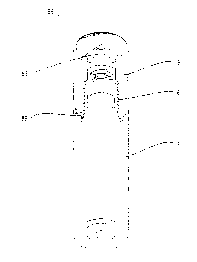
A container with a dispensing plug structure including a tubular plug, a ball,
a
cap, and a container body containing a liquid. The plug has a top opening and
is
provided with three tongues extending integrally in a spaced-apart arrangement
and
on the same level from an inner wall at an intermediate section thereof. Each
of the
tongues has a tail end portion provided with a boss. The ball is inserted into
the
plug via the opening to be supported on the tongues such that the ball has a
portion
projecting from the opening of the plug. The bosses at the tail ends of the
respective tongues together define a triangular plane for supporting the ball
thereon
so that when the ball is rotated in operation to dispense a suitable amount of
the
liquid in the container body, the tongues may elastically control the rotation
of the
ball, and the bosses thereof may support the ball, which allows a suitable
amount of
the liquid contained in the container body when rotated. The cap has a
circular
track formed on a bottom side thereof. A post extends downwardly from a
central
portion of the track. The cap further has an annular opening end provided with
a
toothed face. The track presses against the ball when the cap is put in place,
with
the post abutting against an upper end of the ball to prevent the ball from
movement.
The toothed face is capable of holding firmly to an opening end of the
container body.
Hence, the amounts of liquid dispensed can be controlled and the cap will not
easily
detach from the container body.


Claims

Note: Claims are shown in the official language in which they were submitted.


8
I CLAIM:
1. A container with a dispensing plug structure, comprising a tubular plug, a
ball, a cap, and a container body containing a liquid, wherein said plug has a
top
opening and is provided with three tongues extending integrally in a spaced-
apart
arrangement and on the same level from an inner wall at an intermediate
section
thereof, each of said tongues having a tail end portion provided with a boss,
said ball
being inserted into said plug via said opening to be supported on said tongues
such
that said ball has a potion projecting from said opening of said plug, said
bosses at
the said tail ends of the respective tongues together define a triangular
plane for
supporting said ball thereon so that when said ball is rotated in operation to
dispense
a suitable amount of the liquid in said container body, said tongues may
elastically
control the rotation of said ball, and said bosses thereof may support said
ball, which
allows passage of a suitable amount of the liquid contained in said container
body
when rotated, said cap having a circular track formed on a bottom side
thereof, a post
extending downwardly from a central portion of said track, said cap further
having an
annular opening end provided with a toothed face, said track pressing against
said
ball when said cap is put in place, with said post abutting against an upper
end of said
ball to prevent said ball from movement, said toothed face being capable of
holding
firmly to an opening end of said container body, whereby the amount of liquid
dispensed can be controlled and said cap will not easily detach from said
container

9
body.

Description

Note: Descriptions are shown in the official language in which they were submitted.


CA 02289299 1999-11-10
TITLE: CONTAINEF; WITH A DISPENSL'~1G PLUG STRUCTURE
BACKGROUND OF THE INVENTION
(a) Field of the Invention:
The present invention relates to a container with a dispensing plug structure,
more particularly a container having a dispensing plug structure in which the
amount
of liquid dispensed can be easily controlled.
(b) Description of the; Prior Art:
Perfumes, eau df; toilette., etc., are widely used by both women and men. In
general, the user removes the c;~p of the perfume bottle and presses a
dispensing head
to spray the perfume Get desired spots. In other cases, the user removes the
cap and
pours out a desired amount of perfume onto the hand or into the cap for use.
Problems of conventional perfume dispensers are that the perfume bottle may
slip
from the user's hand vrhen the user presses the dispensing head improperly or
when
the user pours the perfume, resulting in overflowing of the perfume or
breaking of
the perfume bottle. >=iesides, it is difficult to control the amount of the
perfume to be
poured out from the perfume battle.

CA 02289299 1999-11-10
2
SLJ>!vINIARY OF THE INVEI~fTION
A primary object of the present is to provide a container with a dispensing
plug
structure that include:; a tubul;~r plug, a ball, a cap, and a container body
to allow
effective control of dispensing of a liquid contained in the container body
and prevent
detachment of the cap from the container bottle.
Another object of the yresent invention is to provide a container with a
dispensing plug structure in which the plug structure is provided with three
tongues
extending integrally in a spaced-apart arrangement on the same level from an
inner
wall at an intermediate; section thereof, each of the tongues having a boss at
a tail end
thereof. A ball is supported ~on the tongues and has a portion projecting from
an
opening of a container body. The bosses of the tongues define a triangular
plane for
supporting the ball rotatably thereon. The ball can be rotated to dispense a
suitable
amount of a liquid contained in the container body.
A further object of the present invention is to provide a container with a
1 S dispensing plug structure that includes a cap having a bottom side
provided with a
circular track and a post projecting from a central portion of the track. The
post can
prevent a ball of the ~~lug structure from movement. The cap is further
provided
with a toothed face at arl opening end thereof to hold firmly to a container
body.
The foregoing objects and summary provide only a brief introduction to
the present invention. To fully appreciate these and other objects of the

CA 02289299 1999-11-10
3
present invention a:~ well a:~ the invention itself, all of which will become
apparent to those skilled in the art, the following detailed description of
the
invention and the claims should be read in conjunction with the accompanying
drawings. Throughout the specification and drawings identical reference
numerals refer to identical or similar parts. Many other advantages and
features of the present invention will become manifest to those versed in the
art upon making ref erence to the detailed description and the accompanying
sheets of drawings in which a preferred structural embodiment incorporating
the principles of the present invention is shown by way of illustrative
example:

CA 02289299 1999-11-10
BRIEF DESCRIPTION OF TW DRAWINGS
Fig. 1 is a section~~l view of the present invention;
Fig. 2 is an exploded persl>ective view of the present invention;
Fig. 3 are sectional views illustrating operation of the present invention;
and
Fig. 4 are sectional views of the present invention after a cap has put in
place.

CA 02289299 1999-11-10
DETAILED DESCRIPTION OF THE PREFERRED EMBODIMENT
For the purposf~ of promoting an understanding of the principles of the
invention, reference will now be made to the embodiment illustrated in the
drawings. Specific; language will be used to describe same. It will,
5 nevertheless, be understood that no limitation of the scope of the invention
is
thereby intended, such alterations and further modifications in the
illustrated
device, and such further applications of the principles of the invention as
illustrated herein being contemplated as would normally occur to one skilled
in the art to which the invention relates.
With reference to Figs. 1 vto 4, the present invention includes a tubular plug
6, a
ball 66, a cap 8, and a container body 9. The present invention is
characterized in
that the plug 6 has a top opening and is provided with three tongues 61, 62,
63
extending integrally il a spacE;d-apart arrangement and on the same level from
an
inner wall at an intermediate aection thereof. Each of the tongues has a tail
end
portion provided with a boss 615, 625, 635. The ball 66 is inserted into the
plug 6
via the opening to be supported on the tongues 61, 62, 63 such that the ball 6
has a
portion projecting from the opf;ning of the plug 6. The bosses 615, 625, 635
at the
tail ends of the respective ton~;ues 61, 62, 63 together define a triangular
plane for
supporting the ball 6E~ thereon so that when the ball 66 is rotated in
operation, the
tongues 61, 62, 63 may elastically extend to control the rotation of the ball
66, and

CA 02289299 1999-11-10
6
the bosses 615, 625, 6:35 thereof may support the ball 66 that can be pressed
to allow
passage of a suitable <~lnount of the liquid contained in the container body
9. The
cap 8 has a circular track 86 formed on a bottom side thereof. A post 88
extending
from a central portion of the track 86. The cap 8 further has an annular
opening end
provided with a toothed face 89. When the cap 8 is put in place, the track 86
presses against the ball 66 with. the post 88 abutting against the upper end
of the ball
66 to prevent it from movement, and the toothed face 89 can retain firmly an
opening
end of the container body 9 to stable the container body 9, whereby, when not
in use,
the ball 66 will not route to release the liquid in the container body 9, and
the cap 8
will not become loosened to detach from the container body 9. Hence, the
amount
of liquid dispensed can be controlled, and the cap 8 can be firmly positioned
on the
container body 9.
It will be understood that each of the elements described above, or two or
more together may also find a useful application in other types of methods
differing from the type described above.
While certain novel features of this invention have been shown and
described and are painted out in the annexed claim, it is not intended to be
limited to the details above, ~~ince it will be understood that various
omissions,
modifications, substitutions and changes in the forms and details of the
device
illustrated and in its operation can be made by those skilled in the art
without

CA 02289299 1999-11-10
departing in any wa5~ from tree spirit of the present invention.

Representative Drawing
A single figure which represents the drawing illustrating the invention.
Administrative Status

2024-08-01:As part of the Next Generation Patents (NGP) transition, the Canadian Patents Database (CPD) now contains a more detailed Event History, which replicates the Event Log of our new back-office solution.

Please note that "Inactive:" events refers to events no longer in use in our new back-office solution.

For a clearer understanding of the status of the application/patent presented on this page, the site Disclaimer , as well as the definitions for Patent , Event History , Maintenance Fee  and Payment History  should be consulted.

Event History

Description Date
Application Not Reinstated by Deadline 2002-11-12
Time Limit for Reversal Expired 2002-11-12
Deemed Abandoned - Failure to Respond to Maintenance Fee Notice 2001-11-13
Application Published (Open to Public Inspection) 2001-05-10
Inactive: Cover page published 2001-05-09
Inactive: First IPC assigned 2000-01-07
Inactive: IPC assigned 2000-01-07
Inactive: IPC removed 2000-01-07
Filing Requirements Determined Compliant 1999-12-10
Inactive: Filing certificate - No RFE (English) 1999-12-10
Application Received - Regular National 1999-12-08

Abandonment History

Abandonment Date Reason Reinstatement Date
2001-11-13

Fee History

Fee Type Anniversary Year Due Date Paid Date
Application fee - small 1999-11-10
Owners on Record

Note: Records showing the ownership history in alphabetical order.

Current Owners on Record
PAO-YUAN WAN
Past Owners on Record
None
Past Owners that do not appear in the "Owners on Record" listing will appear in other documentation within the application.
Documents

To view selected files, please enter reCAPTCHA code :


To view images, click a link in the Document Description column. To download the documents, select one or more checkboxes in the first column and then click the "Download Selected in PDF format (Zip Archive)" or the "Download Selected as Single PDF" button.

List of published and non-published patent-specific documents on the CPD .

If you have any difficulty accessing content, you can call the Client Service Centre at 1-866-997-1936 or send them an e-mail at CIPO Client Service Centre.


Document
Description 
Date
(yyyy-mm-dd) 
Number of pages   Size of Image (KB) 
Representative drawing 2001-04-29 1 6
Claims 1999-11-09 2 42
Drawings 1999-11-09 4 59
Description 1999-11-09 7 177
Abstract 1999-11-09 1 40
Filing Certificate (English) 1999-12-09 1 164
Reminder of maintenance fee due 2001-07-10 1 112
Courtesy - Abandonment Letter (Maintenance Fee) 2001-12-10 1 183