Sélection de la langue

Search

Sommaire du brevet 2289299 

Énoncé de désistement de responsabilité concernant l'information provenant de tiers

Une partie des informations de ce site Web a été fournie par des sources externes. Le gouvernement du Canada n'assume aucune responsabilité concernant la précision, l'actualité ou la fiabilité des informations fournies par les sources externes. Les utilisateurs qui désirent employer cette information devraient consulter directement la source des informations. Le contenu fourni par les sources externes n'est pas assujetti aux exigences sur les langues officielles, la protection des renseignements personnels et l'accessibilité.

Disponibilité de l'Abrégé et des Revendications

L'apparition de différences dans le texte et l'image des Revendications et de l'Abrégé dépend du moment auquel le document est publié. Les textes des Revendications et de l'Abrégé sont affichés :

  • lorsque la demande peut être examinée par le public;
  • lorsque le brevet est émis (délivrance).
(12) Demande de brevet: (11) CA 2289299
(54) Titre français: CONTENANT AVEC STRUCTURE DISTRIBUTRICE A COUVERCLE
(54) Titre anglais: CONTAINER WITH A DISPENSING PLUG STRUCTURE
Statut: Réputée abandonnée et au-delà du délai pour le rétablissement - en attente de la réponse à l’avis de communication rejetée
Données bibliographiques
Abrégés

Abrégé anglais


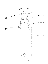
A container with a dispensing plug structure including a tubular plug, a ball,
a
cap, and a container body containing a liquid. The plug has a top opening and
is
provided with three tongues extending integrally in a spaced-apart arrangement
and
on the same level from an inner wall at an intermediate section thereof. Each
of the
tongues has a tail end portion provided with a boss. The ball is inserted into
the
plug via the opening to be supported on the tongues such that the ball has a
portion
projecting from the opening of the plug. The bosses at the tail ends of the
respective tongues together define a triangular plane for supporting the ball
thereon
so that when the ball is rotated in operation to dispense a suitable amount of
the
liquid in the container body, the tongues may elastically control the rotation
of the
ball, and the bosses thereof may support the ball, which allows a suitable
amount of
the liquid contained in the container body when rotated. The cap has a
circular
track formed on a bottom side thereof. A post extends downwardly from a
central
portion of the track. The cap further has an annular opening end provided with
a
toothed face. The track presses against the ball when the cap is put in place,
with
the post abutting against an upper end of the ball to prevent the ball from
movement.
The toothed face is capable of holding firmly to an opening end of the
container body.
Hence, the amounts of liquid dispensed can be controlled and the cap will not
easily
detach from the container body.

Revendications

Note : Les revendications sont présentées dans la langue officielle dans laquelle elles ont été soumises.


8
I CLAIM:
1. A container with a dispensing plug structure, comprising a tubular plug, a
ball, a cap, and a container body containing a liquid, wherein said plug has a
top
opening and is provided with three tongues extending integrally in a spaced-
apart
arrangement and on the same level from an inner wall at an intermediate
section
thereof, each of said tongues having a tail end portion provided with a boss,
said ball
being inserted into said plug via said opening to be supported on said tongues
such
that said ball has a potion projecting from said opening of said plug, said
bosses at
the said tail ends of the respective tongues together define a triangular
plane for
supporting said ball thereon so that when said ball is rotated in operation to
dispense
a suitable amount of the liquid in said container body, said tongues may
elastically
control the rotation of said ball, and said bosses thereof may support said
ball, which
allows passage of a suitable amount of the liquid contained in said container
body
when rotated, said cap having a circular track formed on a bottom side
thereof, a post
extending downwardly from a central portion of said track, said cap further
having an
annular opening end provided with a toothed face, said track pressing against
said
ball when said cap is put in place, with said post abutting against an upper
end of said
ball to prevent said ball from movement, said toothed face being capable of
holding
firmly to an opening end of said container body, whereby the amount of liquid
dispensed can be controlled and said cap will not easily detach from said
container

9
body.

Description

Note : Les descriptions sont présentées dans la langue officielle dans laquelle elles ont été soumises.


CA 02289299 1999-11-10
TITLE: CONTAINEF; WITH A DISPENSL'~1G PLUG STRUCTURE
BACKGROUND OF THE INVENTION
(a) Field of the Invention:
The present invention relates to a container with a dispensing plug structure,
more particularly a container having a dispensing plug structure in which the
amount
of liquid dispensed can be easily controlled.
(b) Description of the; Prior Art:
Perfumes, eau df; toilette., etc., are widely used by both women and men. In
general, the user removes the c;~p of the perfume bottle and presses a
dispensing head
to spray the perfume Get desired spots. In other cases, the user removes the
cap and
pours out a desired amount of perfume onto the hand or into the cap for use.
Problems of conventional perfume dispensers are that the perfume bottle may
slip
from the user's hand vrhen the user presses the dispensing head improperly or
when
the user pours the perfume, resulting in overflowing of the perfume or
breaking of
the perfume bottle. >=iesides, it is difficult to control the amount of the
perfume to be
poured out from the perfume battle.

CA 02289299 1999-11-10
2
SLJ>!vINIARY OF THE INVEI~fTION
A primary object of the present is to provide a container with a dispensing
plug
structure that include:; a tubul;~r plug, a ball, a cap, and a container body
to allow
effective control of dispensing of a liquid contained in the container body
and prevent
detachment of the cap from the container bottle.
Another object of the yresent invention is to provide a container with a
dispensing plug structure in which the plug structure is provided with three
tongues
extending integrally in a spaced-apart arrangement on the same level from an
inner
wall at an intermediate; section thereof, each of the tongues having a boss at
a tail end
thereof. A ball is supported ~on the tongues and has a portion projecting from
an
opening of a container body. The bosses of the tongues define a triangular
plane for
supporting the ball rotatably thereon. The ball can be rotated to dispense a
suitable
amount of a liquid contained in the container body.
A further object of the present invention is to provide a container with a
1 S dispensing plug structure that includes a cap having a bottom side
provided with a
circular track and a post projecting from a central portion of the track. The
post can
prevent a ball of the ~~lug structure from movement. The cap is further
provided
with a toothed face at arl opening end thereof to hold firmly to a container
body.
The foregoing objects and summary provide only a brief introduction to
the present invention. To fully appreciate these and other objects of the

CA 02289299 1999-11-10
3
present invention a:~ well a:~ the invention itself, all of which will become
apparent to those skilled in the art, the following detailed description of
the
invention and the claims should be read in conjunction with the accompanying
drawings. Throughout the specification and drawings identical reference
numerals refer to identical or similar parts. Many other advantages and
features of the present invention will become manifest to those versed in the
art upon making ref erence to the detailed description and the accompanying
sheets of drawings in which a preferred structural embodiment incorporating
the principles of the present invention is shown by way of illustrative
example:

CA 02289299 1999-11-10
BRIEF DESCRIPTION OF TW DRAWINGS
Fig. 1 is a section~~l view of the present invention;
Fig. 2 is an exploded persl>ective view of the present invention;
Fig. 3 are sectional views illustrating operation of the present invention;
and
Fig. 4 are sectional views of the present invention after a cap has put in
place.

CA 02289299 1999-11-10
DETAILED DESCRIPTION OF THE PREFERRED EMBODIMENT
For the purposf~ of promoting an understanding of the principles of the
invention, reference will now be made to the embodiment illustrated in the
drawings. Specific; language will be used to describe same. It will,
5 nevertheless, be understood that no limitation of the scope of the invention
is
thereby intended, such alterations and further modifications in the
illustrated
device, and such further applications of the principles of the invention as
illustrated herein being contemplated as would normally occur to one skilled
in the art to which the invention relates.
With reference to Figs. 1 vto 4, the present invention includes a tubular plug
6, a
ball 66, a cap 8, and a container body 9. The present invention is
characterized in
that the plug 6 has a top opening and is provided with three tongues 61, 62,
63
extending integrally il a spacE;d-apart arrangement and on the same level from
an
inner wall at an intermediate aection thereof. Each of the tongues has a tail
end
portion provided with a boss 615, 625, 635. The ball 66 is inserted into the
plug 6
via the opening to be supported on the tongues 61, 62, 63 such that the ball 6
has a
portion projecting from the opf;ning of the plug 6. The bosses 615, 625, 635
at the
tail ends of the respective ton~;ues 61, 62, 63 together define a triangular
plane for
supporting the ball 6E~ thereon so that when the ball 66 is rotated in
operation, the
tongues 61, 62, 63 may elastically extend to control the rotation of the ball
66, and

CA 02289299 1999-11-10
6
the bosses 615, 625, 6:35 thereof may support the ball 66 that can be pressed
to allow
passage of a suitable <~lnount of the liquid contained in the container body
9. The
cap 8 has a circular track 86 formed on a bottom side thereof. A post 88
extending
from a central portion of the track 86. The cap 8 further has an annular
opening end
provided with a toothed face 89. When the cap 8 is put in place, the track 86
presses against the ball 66 with. the post 88 abutting against the upper end
of the ball
66 to prevent it from movement, and the toothed face 89 can retain firmly an
opening
end of the container body 9 to stable the container body 9, whereby, when not
in use,
the ball 66 will not route to release the liquid in the container body 9, and
the cap 8
will not become loosened to detach from the container body 9. Hence, the
amount
of liquid dispensed can be controlled, and the cap 8 can be firmly positioned
on the
container body 9.
It will be understood that each of the elements described above, or two or
more together may also find a useful application in other types of methods
differing from the type described above.
While certain novel features of this invention have been shown and
described and are painted out in the annexed claim, it is not intended to be
limited to the details above, ~~ince it will be understood that various
omissions,
modifications, substitutions and changes in the forms and details of the
device
illustrated and in its operation can be made by those skilled in the art
without

CA 02289299 1999-11-10
departing in any wa5~ from tree spirit of the present invention.

Dessin représentatif
Une figure unique qui représente un dessin illustrant l'invention.
États administratifs

2024-08-01 : Dans le cadre de la transition vers les Brevets de nouvelle génération (BNG), la base de données sur les brevets canadiens (BDBC) contient désormais un Historique d'événement plus détaillé, qui reproduit le Journal des événements de notre nouvelle solution interne.

Veuillez noter que les événements débutant par « Inactive : » se réfèrent à des événements qui ne sont plus utilisés dans notre nouvelle solution interne.

Pour une meilleure compréhension de l'état de la demande ou brevet qui figure sur cette page, la rubrique Mise en garde , et les descriptions de Brevet , Historique d'événement , Taxes périodiques et Historique des paiements devraient être consultées.

Historique d'événement

Description Date
Demande non rétablie avant l'échéance 2002-11-12
Le délai pour l'annulation est expiré 2002-11-12
Réputée abandonnée - omission de répondre à un avis sur les taxes pour le maintien en état 2001-11-13
Demande publiée (accessible au public) 2001-05-10
Inactive : Page couverture publiée 2001-05-09
Inactive : CIB en 1re position 2000-01-07
Inactive : CIB attribuée 2000-01-07
Inactive : CIB enlevée 2000-01-07
Exigences de dépôt - jugé conforme 1999-12-10
Inactive : Certificat de dépôt - Sans RE (Anglais) 1999-12-10
Demande reçue - nationale ordinaire 1999-12-08

Historique d'abandonnement

Date d'abandonnement Raison Date de rétablissement
2001-11-13

Historique des taxes

Type de taxes Anniversaire Échéance Date payée
Taxe pour le dépôt - petite 1999-11-10
Titulaires au dossier

Les titulaires actuels et antérieures au dossier sont affichés en ordre alphabétique.

Titulaires actuels au dossier
PAO-YUAN WAN
Titulaires antérieures au dossier
S.O.
Les propriétaires antérieurs qui ne figurent pas dans la liste des « Propriétaires au dossier » apparaîtront dans d'autres documents au dossier.
Documents

Pour visionner les fichiers sélectionnés, entrer le code reCAPTCHA :


Pour visualiser une image, cliquer sur un lien dans la colonne description du document. Pour télécharger l'image (les images), cliquer l'une ou plusieurs cases à cocher dans la première colonne et ensuite cliquer sur le bouton "Télécharger sélection en format PDF (archive Zip)" ou le bouton "Télécharger sélection (en un fichier PDF fusionné)".

Liste des documents de brevet publiés et non publiés sur la BDBC .

Si vous avez des difficultés à accéder au contenu, veuillez communiquer avec le Centre de services à la clientèle au 1-866-997-1936, ou envoyer un courriel au Centre de service à la clientèle de l'OPIC.


Description du
Document 
Date
(aaaa-mm-jj) 
Nombre de pages   Taille de l'image (Ko) 
Dessin représentatif 2001-04-29 1 6
Revendications 1999-11-09 2 42
Dessins 1999-11-09 4 59
Description 1999-11-09 7 177
Abrégé 1999-11-09 1 40
Certificat de dépôt (anglais) 1999-12-09 1 164
Rappel de taxe de maintien due 2001-07-10 1 112
Courtoisie - Lettre d'abandon (taxe de maintien en état) 2001-12-10 1 183