Note: Descriptions are shown in the official language in which they were submitted.
CA 02289386 1999-11-12
SJ-10669
- 1 -
TITLE: TUBE CUTTING DEVICE
FIELD OF THE INVENTION
The present invention relates to a tube cutting
device for perforating tubing such as profiled drainage
tubing.
BACKGROUND OF THE INVENTION
In some uses of plastic pipe, it is a requirement
that the pipe be perforated. In one example only,
underground profiled drainage pipe is provided with small
cuts or slits spaced from one another around the troughs of
the profiled pipe.
In the past, different devices have been either
used or proposed for perforating such pipe. United States
Patent 4,180,357 and 4,218,164 both issued to Gerd Lupke
disclose tube perforating devices in the form of a
plurality of screw-like cutters rotatably mounted on fixed
shafts around a center bore through which tubing is passed
for perforation by the screw-like members. Although the
devices in both of these patents are very efficient in
operation, they are not easily adjusted for different tube
diameters.
United States Patents 5,381,711 and 5,385,073 both
owned by Truemner et al, disclose tube perforators having
driver cutter wheels supported by drive shafts at different
positions around the perforators. According to both of
these patents the drive shafts are at an angle, i.e. not
parallel to the axis of the tube passed through the
perforator. The angling of the drive shafts produces a
tipping of the cutter wheels which, according to each of
the patents, helps keep the wheels in the troughs of the
tube and to accommodate very minor fluctuations in the
CA 02289386 1999-11-12
SJ-10669
- 2 -
tubing. In addition, according to each of these patents
the driver cutter wheels are inter-changeable with other
driver cutter wheels to accommodate more substantial
variances in the tubing such as for example, tubing of
different diameters.
SLJNMARY OF THE PRESENT INVENTION
The present invention provides a tube cutting
device which very quickly and easily adjusts for variances
in tubing passing through the device whether those
variances be as a result of different sizes of tubing or
whether they be as a result of for example different tube
sections such as coupling sections produced in the tubing
which should not be cut.
In particular, the tube cutting device of the
present invention which produces a plurality of cuts or
slits around tubing passed through the device comprises a
plurality of rotatable members located at different
circumferential positions around a tube passage through the
device. Each rotatable member is provided with a tube
cutter which is directed at and away from the tube passage
with rotation of each member.
In accordance with the present invention, the
rotatable members are adjustable radially of the tube
passage for accommodating diametric variances in the tubing
passed through the device.
According to an aspect of the present invention a
plurality of the tube cutters and in some cases all of the
rotatable tube cutter members are responsive to a single
controller which produces simultaneous uniform radial
adjustment of all of the members.
CA 02289386 1999-11-12
SJ-10669
- 3 -
BRIEF DESCRIPTION OF THE DRAWINGS
The above as well as other advantages and features
of the present invention will be described in greater
detail according to the preferred embodiments of the
present invention in which;
Figure 1 is a sectional view through a tube cutting
device according to a preferred embodiment of the present
invention;
Figure 2 is an enlarged sectional view of one of
the individual tube cutting stations from the device of
Figure 1;
Figure 3 is a sectional view of a tube cutting
device according to a further preferred embodiment of the
present invention;
DETAILED DESCRIPTION ACCORDING TO THE PREFERRED EMBODIMENTS
OF THE PRESENT INVENTION IN WHICH:
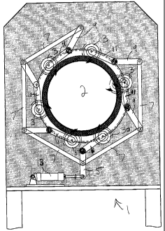
Figure 1 shows a cutting device generally indicated
at 1 for cutting tubing and in this case profiled plastic
tubing passed through the device. The tube cutting device
includes a plurality of individual cutting stations 3 at
circumferentially spaced positions around a central tube
passage or bore 2 through the device.
The details of each of the tube cutting stations 3
are better shown in Figure 2 of the drawings and will be
described later in detail.
Returning to Figure 1 the key to the present
invention lies in the radial adjustability of each of the
cutting stations 3. In the particular example shown, this
adjustability is provided through a mechanical linkage
system comprising a plurality of levers pivotally
interconnected to one another.
CA 02289386 1999-11-12
SJ-10669
- 4 -
More particularly, the linkage system comprises a
main or master lever 5 which, through a single movement of
this lever controls a plurality of slave levers to produce
simultaneous uniform radial adjustment of each of the
cutting stations. These slave levers comprise slave lever
6 which is pivotally connected to the interior end of
master or main lever 5 and a further plurality of slave
levers 7 outwardly around the device. As can be seen in
Figure 1, two of these slave levers pivotally connect
centrally of the master lever 5.
Further slave levers 9 pivotally connect to the
ends of the levers 7 and these slave levers 9 then
pivotally connect to slave levers 11 which rotably support
each of the cutting stations 3. The one minor difference
in the overall set up is found where slave lever 6 which as
noted above is pivotally connected to the interior end of
master lever 5 is used to support the cutting station 3a.
The actual construction of cutting station 3a is identical
to the cutting stations 3.
Master lever 5 is pivotally connected at its outer
end to a reciprocating plunger 13.
Movement of the plunger in one direction, i.e.
outward extension of the plunger, acts directly on the
master lever which in turn causes movement of all of the
slave levers to pull each of the cutting stations outwardly
from the position shown in Figure 1. The degree of
extension on the plunger dictates the degree of movement of
the cutting stations. For example, the plunger can be
extended sufficiently far to pull the cutting stations
completely away from the center bore 2 which would allow
something as large as a coupling section of the tube to
pass through the device without coming into contact with
the cutting stations. The cutters can also be pulled
CA 02289386 2003-10-31
- 5 -
outwardly to cut larger diameter tubing.
If it is desired to pull each of the cutting
stations radially inwardly from the Figure 1 position to
cut for example smaller diameter tubing, again a single
movement of plunger 13, i.e. retraction of the plunger
produces uniform inward adjustment of the cutting stations
through the master and slave levers of the linkage system.
As noted above, one of the individual cutting
stations 3 is well shown in Figure 2 of the drawings. This
cutting station comprises both a means for driving the tube
through the device as well as a means for cutting the tube.
This concept is similar to that disclosed in the two
earlier Lupke patents although the actual construction of
cutter station 3 is novel to the present invention.
More particularly, cutting station 3 comprises a
first disk like member 15 having a thread 17 on an exterior
surface of the disk. A second disk-like member 19 is
located in a downstream position relative to the first disk
like member. The exterior surface of disk 19 is provided
with a helical thread portion 21 which wraps partially
around the disk. This helical thread portion 21 is
intersected by a rib portion 23 supporting the actual tube
cutter 25.
As well shown in Figure 2 of the drawings, rib
portion 23 is straight rather than having the helical
configuration of the thread portion 21. Accordingly, the
rib lies at 90° to the axis of the tubing passing through
the device and the cut produced by cutter 25 is produced in
the same direction.
Disk members 15 and 19 are mounted on a common
rotating support 29. The disk 15 is fixed while the disk
CA 02289386 2003-10-31
- 6 -
19 is movable longitudinally of that support. As
suc h, disk 15 and specifically the thread 17 on this fixed
disk engages within the troughs of the profiled pipe and the
rotation of the disk, because of the pitch on the thread
pushes the pipe through the device.
At the same time, the thread portion 21 on the
disk 19 also engages in the troughs of the pipe.
However, because of its movable feature, this disk will
slide in a downstream 10 direction on support 29 as it is.
rotated by the thread meshing with the pipe.
The disk 19 will rotate into position such that the
flat rib 23 and the cutter 25 supported by the rib moves
into the trough. As a result of the disk moving
with the pipe, the cutter will perform the desired right
angle cut without any resistance to the pipe movement through
the device .
Once the rib 25 has cleared from the trough
with the rotation of disk 19 to complete the pipe cut in this
particular area, disk 19 will return in a downstream position
adjacent disk 15 to perform a new cutting operation on the
next trough presented to it. This occurs 25 as a
result of two things. Firstly, a spring 31 is
provided on the downstream end of disk 19 and this spring is
trapped in position by means of an end stop 31 on support 29.
This end stop holds the entire assembly together.
Secondly, the pitch of thread portion 21 on disk
19 is such that after the cut has been made, disk 19 threads
itself under the influence of spring 31 back towards
disk 19 as it engages within the next trough of the
pipe. This action is 35 again similar to that
described in United States Patent 4,218,164.
CA 02289386 2003-10-31
As is also described in both United States Patents
4,180,357 and 4,218,164 all of the cutting stations 3 may
be rotated at the same time by a single drive belt for all
of the cutting stations. This drive belt will wrap in
opposite directions around adjacent rotatable supports of
the cutting stations to drive the adjacent stations in
opposite directions preventing tube rotation within the
device. Additional means such as a soft tube grip may also
be provided to help hold the tube against rotation while it
is being cut.
Figure 3 of the drawings shows a modified tube
cutting device generally indicated at 22. This device
includes a plurality of rotary tube cutting stations 23 at
circumferentially spaced locations around a center tube
passage 24 through the device.
In this particular case the tube cutters 23 rather
than being radially adjustable by a pivotal linkage system
move in and out relative to passage 24 by a radially
directed slide adjustment. In particular each of the
cutters 23 is rotably supported on a mount or bar 27
supported by a frame 25. The bar 27 slides in and out of
the frame for the radial adjustment of the tube cutters.
In the embodiment shown in Figure 3, operation of
the slide system is controlled by an electronic controller.
This controller is fed impulses by sensing means on the
surface of the tubing which feed information to the
controller for its operation.
For example, the sensors would pick up the
approach of a large diameter tube region such as a coupling
whereby the controller would cause the tube cutters to pull
outwardly away from the cutting position thereby allowing
the coupling section to pass through the device. Similar
CA 02289386 2003-10-31
sensors could be used to operate the mechanical control
system earlier described.
Again, with the device of Figure 3, like the device
of Figure 1 all of the cutters may be adjusted
simultaneously and uniformly with one another.
According to another aspect of the invention, it
would only be required to move some of the cutters into a
cutting position while either retracting or holding the
other cutters away form the cutting position. For
instance, it may only be required to cut the bottom portion
of the tube. This can also be accomplished using cutting
device 22_where the control would cause the cutters in the
top part of the device to move radially outwardly from the
cutting position. The cutters in the lower part of the
device would not be moved.
Also for this situation, means are provided to
prevent pipe rotation which would otherwise occur because
of the imbalance in the cutting area. These means are in
the form of tube grips 3 which include a housing 33 and a
soft tip plunger 35 which is moved radially inwardly
against the tube to hold it against rotation.
Although various preferred embodiments of the
present invention have been described in detail, it will be
appreciated by those skilled in the art that variations may
be made without departing from the spirit of the invention
or the scope of the appended claims.