Note: Descriptions are shown in the official language in which they were submitted.
CA 02289437 1999-11-12
1
TRANSMITTING SYSTEM FOR SMALL-SIZED VEHICLE
BACKGROUND OF THE INVENTION
FIELD OF THE INVENTION
The present invention relates to a transmitting system
for a small-sized vehicle, in which a crankshaft of an engine
and an input shaft of a mufti-stage transmission are connected
to each other through a fluid transmitting means including a
pump impeller connected to the engine, and a turbine impeller
connected to the mufti-stage transmission, i.e., through a
torque converter or a fluid coupling.
2. DESCRIpTT_ON OF THE RELATED ART
Such transmitting system for small-sized vehicles is
already known, as disclosed in, for example, Japanese Patent
Application Laid-open No.57-69163.
In such known transmitting system, as disclosed in the
above Publication, the crankshaft of the engine and the input
shaft of the mufti-stage transmission are connected to each
other only through the torque converter, so that a torque shock
generated at the time of starting the vehicle or during shifting
is absorbed by a slipping action of the torque converter.
However, the known transmitting system suffers from the
following drawbacks: The torque converter or the fluid
coupling has a slipping function, but performs the transmission
of a torque to certain degree , as long as power is input from
the engine to the torque converter or the fluid coupling.
CA 02289437 1999-11-12
2
Therefore, in the known system, at the time of starting the
vehicle in which the transmission is switched over from a
neutral position to a low or first-speed position, a creep
phenomenon is produced in which power is transmitted to a driven
wheel of the vehicle to certain degree , even if the engine is
in an idling state. During traveling of the vehicle, the
friction always occurs in switching and sliding portions of the
transmission due to the transmitted torque. For this reason,
there are inconveniences that the resistance to the switching
of the transmission is large, and a large shifting load is
required.
SI1MNLA_RY OF THE INVENTION
Accordingly, it is an object of the present invention to
provide a transmitting system for a small-sized vehicle
above-described, wherein the creep phenomenon is eliminated,
and the shifting operation of the transmission can be carried
out lightly, and moreover, during cruising of the vehicle, the
slipping of the fluid transmitting means is inhibited to enhance
the transmitting efficiency.
To achieve the above object, according to a first aspect
and feature of the present invention, there is provided a
transmitting system for a small-sized vehicle in which a
crankshaft of an engine and an input shaft of a multi-stage
transmission are connected to each other through a fluid
transmitting means including a pump impeller connected to the
engine, and a turbine impeller connected to the multi-stage
CA 02289437 2003-06-16
70488-149
3
transmission, wherein the transmitting system includes a
shifting clutch which is interposed between the crankshaft
of the engine and the input shaft of the multi-stage
transmission, the sifting clutch being in a series relation
to the fluid transmitting means and a lock-up clutch which
is interposed between the pump impeller and the turbine
impeller of the fluid transmitting means, the lock-up clutch
being capable of connecting both the impellers directly to
each other, and where said fluid transmitting means and said
shifting clutch are connected to the input shaft of the
multi-stage transmission via a primary reducing device.
The fluid transmitting means corresponds to a
torque converter T in each of embodiments of the present
invention which will be described hereinafter.
With the first feature, during idling of the
engine, the transmitting of power to the shifting clutch and
the like can be cut off by controlling the shifting clutch
to its OFF state irrespective of the presence of the fluid
transmitting means, even in a low or first-speed position of
the transmission, thereby preventing the creep phenomenon.
During shifting, the transmission can be brought into an
unloaded state irrespective of the presence of the fluid
transmitting means by first controlling the shifting clutch
to its OFF state, thereby conducting the shifting lightly
without generation of a torque shock.
Moreover, during cruising of the vehicle, if the
lock-up clutch is controlled to its ON state, the pump
impeller and the turbine impeller are connected directly to
each other and hence, the slipping between both the
impellers can be eliminated to
CA 02289437 1999-11-12
4
prevent a loss of power.
According to a second aspect and feature of the present
invention, in addition to the first feature, the lock-up clutch
comprises a pump extension connected to the pump impeller and
surrounding the turbine impeller, a pressure receiving plate
coupled to a tip end of the pump extension to define, within
the pump extension, a hydraulic pressure chamber communicating
with an oil chamber defined between the pump impeller and the
turbine impeller, a pressing plate opposed to the pressure
receiving plate and biased toward the pressure receiving plate
by a hydraulic pressure in the hydraulic pressure chamber, an
annular friction clutch plate interposed between the pressure
receiving plate and the pressing plate and connected to the
turbine impeller, first and second valve bores provided in the
pressing plate and the pressure receiving plate on the side of
an inner periphery of the friction clutch plate, respectively,
a control valve provided in the pressing plate to close the first
valve bore, a control rod which is received in the first and
second valve bores and movable between a retracted position in
which the control rod causes the inner periphery of the friction
clutch plate to be open outside the second valve bore, while
permitting the closing of the control valve, and an advanced
position in which the control rod causes the control valve to
be open to permit the inner periphery of the friction clutch
plate to communicate with the hydraulic pressure chamber, while
closing the second valve bore, and an operating means for
CA 02289437 1999-11-12
operating the control rod.
The operating means corresponds to a lock-up clutch
operating shaft 86 in a first embodiment of the present
invention which will be described hereinafter.
With the second feature, if the control rod is operated
to the retracted position, the pressing plate can clamp the
friction clutch plate between the pressing plate and the
pressure receiving plate under the action of a hydraulic
pressure transmitted from the fluid transmitting means to the
hydraulic pressure chamber, whereby the lock-up clutch can be
brought into its ON state . If the control rod is operated to
the advanced position, the hydraulic pressure in the hydraulic
pressure chamber can be applied to opposite sides of the
pressing plate to eliminate the clamping force to the friction
clutch plate, whereby the lock-up clutch can be brought into
its OFF state. In this OFF state, the control rod closes the
second valve bore and hence, the useless leakage of the
hydraulic pressure from the hydraulic pressure chamber can be
prevented.
According to a third aspect and feature of the present
invention, in addition to the first or second feature, a one-way
clutch is interposed between the crankshaft and the turbine
impeller and brought into its ON state, when the turbine
impeller receives a reverse load torque.
With the third feature, at the time of an engine brake
during traveling of the vehicle, the one-way clutch is brought
CA 02289437 1999-11-12
6
into its ON state by application of the reverse load torque to
the turbine impeller. Therefore, the turbine impeller and the
crankshaft are connected directly to each other, and the reverse
load torque is transmitted to the crankshaft without via the
fluid transmitting means and thus, a good engine brake effect
can be provided.
According to a fourth aspect and feature of the present
invention, in addition to the first feature, the lock-up clutch
is constructed such that it depends on the rotational speed of
the pump impeller and it automatically operates, when the
rotational speed of the pump impeller becomes equal to or higher
than a predetermined value.
With the fourth feature, when the rotational speed of the
pump impeller becomes equal to or higher than the predetermined
value, the pump impeller and the turbine impeller of the fluid
transmitting means can be automatically connected directly to
each other.
According to a fifth aspect and feature of the present
invention, in addition to the fourth feature, the lock-up clutch
comprises a pump extension connected to the pump impeller and
surrounding the turbine impeller, a pressure receiving plate
coupled to a tip end of the pump extension to define, within
the pump extension, a hydraulic pressure chamber communicating
with an oil chamber defined between the pump impeller and the
turbine impeller, a pressing plate opposed to the pressure
receiving plate for advancing and retracting movements, an
i
CA 02289437 1999-11-12
7
annular friction clutch plate interposed between the pressure
receiving plate and the pressing plate and connected to the
turbine impeller, a return spring for biasing the pressing plate
in a direction to be retracted relative to the pressure
receiving plate, and an escape bore which permits the
communication between the inside and outside of the pressure
receiving plate on an inner peripheral side of the friction
clutch plate, wherein when the rotational speed of the pump
impeller becomes equal to or higher than the predetermined value ,
the pressing plate clamps the friction clutch plate in
cooperation with the pressure receiving plate under the action
of a centrifugal hydraulic pressure in the hydraulic pressure
chamber which is raised in accordance with the rotational speed
of the pump impeller.
With the fifth feature, the automatic control of the
lock-up clutch depending on the rotational speed of the pump
impeller can be conducted easily.
According to a sixth aspect and feature of the present
invention, in addition to the first feature, the lock-up clutch
is constructed such that it depends on the rotational speed of
the turbine impeller and it operats automatically when the
rotational speed of the turbine impeller becomes equal to or
higher than a predetermined value.
With the sixth feature , when the rotational speed of the
turbine impeller becomes equal to or higher than the
predetermined value, the pump impeller and the turbine impeller
i
CA 02289437 1999-11-12
8
of the fluid transmitting means can be automatically connected
directly to each other.
r
According to a seventh aspect and feature of the present
6
invention, in addition to the sixth feature, the lock-up clutch
comprises a clutch cylinder connected to the turbine impeller,
a pressing piston slidably received in a cylinder bore in the
clutch cylinder to define a hydraulic pressure chamber, a piston
return spring for biasing the pressing piston toward the
hydraulic pressure chamber, a means for introducing the oil into
the hydraulic pressure chamber, and a friction engagement means
provided between the clutch cylinder and the pump impeller,
wherein when the rotational speed of the turbine impeller
becomes equal to or higher than the predetermined value, the
pressing piston operates the friction engagement means under
the action of a centrifugal hydraulic pressure within the
hydraulic pressure chamber which is raised in accordance with
the rotational speed of the turbine impeller to connect the
clutch cylinder and the pump impeller directly to each other.
The friction engagement means corresponds to driving
friction clutch plates 110, driven friction clutch plates 111
and transmitting claws 112 in a third embodiment of the present
invention which will be described hereinafter, and the oil
introducing means corresponds to the inlet bore 117 in the third
embodiment.
With the seventh feature, the automatic control of the
lock-up clutch depending on the rotational speed of the turbine
i
CA 02289437 1999-11-12
9
impeller can be carried out easily.
According to an eighth aspect and feature of the present
invention, in addition to the seventh feature, the clutch
cylinder is provided with an escape bore which opens an outer
periphery of the hydraulic pressure chamber to the outside, and
a centrifugal valve which opens the escape bore, when the
rotational speed of the clutch cylinder is lower than a
predetermined value, and closes the escape bore, when the
rotational speed of the clutch cylinder is equal to or higher
than the predetermined value.
With the eighth feature, when the rotational speed of the
clutch cylinder is lower than the predetermined value, the
pressure remaining in the hydraulic pressure chamber can be
released promptly through the escape bore by opening of the
centrifugal valve to enhance the turning-off performance of the
lock-up clutch, and a foreign matter such as a cut powder within
the hydraulic pressure chamber can be discharged through the
escape bore along with the oil. When the rotational speed of
the clutch cylinder is equal to or higher than the predetermined
value, the rising of the hydraulic pressure in the hydraulic
pressure chamber can be conducted by closing of the centrifugal
valve, and the operation of the lock-up clutch cannot be
impeded.
The above and other objects, features and advantages of
the invention will become apparent from the following
description of the preferred embodiments taken in conjunction
CA 02289437 1999-11-12
with the accompanying drawings.
Figs.l to 12 show a first embodiment of the present
invention, wherein
Fig.l is a side view of a motorcycle to which the present
invention is applied;
Fig.2 is a vertical sectional view of a power unit mounted
in the motorcycle;
Fig.3 is an enlarged vertical sectional view of a
transmitting system in the power unit;
Fig. 4 is a sectional view taken along a line 4-4 in Fig.
3;
Fig. 5 is a view taken along a line 5-5 in Fig.3;
Fig. 6 is a side view of the transmitting system;
Fig.7 is an enlarged view showing an outlet valve in a
shifting clutch in a closed state in Fig.3;
Fig.8 is an enlarged view showing the outlet valve in an
opened state;
Fig.9 is a sectional view taken along a line 9-9 in Fig.3;
Fig.lO is a sectional view taken along a line 10-10 in
Fig.3;
Fig.ll is an enlarged view showing a control valve in
a lock-up clutch in a closed state in Fig.3;
Fig . 12 is an enlarged view showing the control valve in
an opened state;
Fig. 13 is a sectional view similar to Fig. 3, but according
CA 02289437 1999-11-12
11
to a second embodiment of the present invention;
Fig. 14 is a sectional view similar to Fig.3, but
according to a third embodiment of the present invention;
Figs. l5 to 17 show a fourth embodiment of the present
invention, wherein
Fig.l5 is a side view of a four-wheel buggy to which the
present invention is applied;
Fig. l6 is a plan view of the four-wheel buggy, taken
vertically through the power unit; and
Fig.l7 is an enlarged vertical sectional view of a
transmitting system for the power unit.
A first embodiment of the present invention will first
be described with reference to Figs.l to 12.
Referring to Fig. 1, a saddle Sm is mounted on a motorcycle
Vm at an upper portion of a body frame Fm supporting a front
wheel Wf and a rear wheel Wr, and a power unit P is mounted at
a lower portion of the body frame Sm. A fuel tank Tfm is disposed
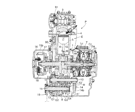
As shown in Figs . 1 and 2 , the power unit P is comprised
of an engine E and a multi-stage transmission M which are formed
integrally each other. The engine E includes, as
conventionally normal, a crankshaft 2 carried in a crankcase
1 with a pair of left and right ball bearings 3 and 3' interposed
therebetween, and a piston 7 slidably received in a cylinder
bore 5a in a cylinder block 5 and connected to the crankshaft
2 through a connecting rod 6. The engine E is disposed with
CA 02289437 1999-11-12
12
the crankshaft 2 turned in a lateral direction of the motorcycle
Vm. A cylinder head 4 is coupled to the cylinder block 5 to
define a combustion chamber 4a between the cylinder head 4 and
a top surface of the piston 7. Provided in the cylinder head
4 are intake and exhaust valves (not shown) for opening and
closing intake and exhaust bores connected to the combustion
chamber 4a, and a cam shaft 9 adapted to open and close the intake
and exhaust valves. The cam shaft 9 is rotatably carried in
the cylinder head 4 in parallel to the crankshaft 2.
A transmission case 8 is integrally connected to the
crankcase 1, and input and output shafts 10 and 11 of the
mufti-stage transmission M, which are disposed in parallel to
the crankshaft 2, are supported by opposite left and right
sidewalls of the transmission case 8 with ball bearings 12 and
12'; 13 and 13' interposed therebetween, respectively. A
first-speed gear train G1, a second-speed gear train G2, a
third-speed gear train G3 and a fourth-speed gear train G4 are
disposed in the named order from the left as viewed in Fig.2
over the input and output shafts 10 and 11. A driven gear G2b
in the second-speed gear train G2 and a driving gear G3a in the
third-speed gear train G3 also serve as shifting gears . When
both of the shifting gears G2b and G3a are in their neutral
positions , the transmission M is in a neutral state . When the
shifting gear G2b is moved leftwards or rightwards as viewed
in Fig.2, the first-speed gear train G1 or the third-speed gear
train G3 is established. When the shifting gear G3a is moved
70488-149
CA 02289437 1999-11-12
13
leftwards or rightwards as viewed, the second-speed gear train
G2 or the fourth-speed gear train G4 is established. The
shifting gears G2b and G3a are operated by a known pedal-type
changing device or another manual changing device which is not
shown.
A right end of the crankshaft 2 and a right end of the
input shaft 10 of the transmission M are connected to each other
through a shifting clutch Cc, a torque converter T and a primary
reducing device 14 which are connected together in series
outside the crankcase 1 and the transmission case 8. In this
case, especially, the shifting clutch Cc, the torque converter
T and a driving gear 14a of the primary reducing device 14 are
mounted on the crankshaft 2 in the order of the driving gear
14a, the torque converter T and the shifting clutch Cc from the
right sidewall of the crankcase 1 toward the outside . A right
side cover 15a, which covers the shifting clutch Cc, the torque
converter T and the driving gear 14a, is bonded to right end
faces of the crankcase 1 and the trasmission case 8.
A rotor 17 of a generator 16 is secured to a left end of
the crankshaft 2 , and a stator 18 of the generator 16 is mounted
to a left side cover 15b which is bonded to a left end face of
the crankshaft 1 to cover the generator 16. A continuous timing
transmitting chamber 90 is defined in those left sidewalls of
the crankcase 1 and the cylinder block 5, which are opposite
to the torque converter T and the primary reducing device 14.
A timing transmitting device 91 for transmitting the rotation
CA 02289437 1999-11-12
14
of the crankshaft 2 through a reduction to one half to the cam
shaft 9 is accommodated in the transmitting chamber 90. Thus,
a group of the primary reducing device 14 , the torque converter
T and the shifting clutch Cc and a group of the timing
transmitting device 91 and the generator 16 are disposed at
opposite ends of the crankshaft 2 in such a manner that the inside
of the crankcase 1, i.e., a crank chamber, is sandwiched
therebetween.
As shown in Figs.2 and 3, provided in the crankshaft 2
are an upstream supply oil passage 27a which opens into a right
end face of the crankshaft 2, a downstream supply oil passage
27b which communicates with a needle bearing 49 on an outer
peripheral surface of a crank pin supporting a larger end of
the connecting rod 6, an orifice 48 which communicates directly
with both the oil passages 27a and 27b, a first flow-in bore
43a extending radially from the upstream supply oil passage 27a
toward the shifting clutch Cc, a second flow-in bore 43b
extending radially from the upstream supply oil passage 27a
toward the torque converter T, and a flow-out bore 45 extending
radially from the downstream supply oil passage 27b toward the
torque converter T. An oil pumped from an oil reservoir 46 by
an oil pump 44 driven by the engine E is fed under a pressure
through an oil passage 27 defined in the right side cover 15a
to the upstream supply oil passage 27a. The oil reservoir 46
is defined in bottoms of the crankcase 1, the transmission case
8 and the right side cover 15a.
CA 02289437 1999-11-12
A chain-type final reducing device 19 which drives the
rear wheel ( not shown ) of the motorcycle is connected to a left
end of the output shaft 11 of the transmission M outside the
transmission case 8.
Referring to Figs . 2 and 3 , the shifting clutch Cc includes
a cylindrical clutch casing 20 having an end wall 20a at its
one end and a boss 20b spline-coupled to the crankshaft 2 at
its central portion, a pressing plate 21 disposed within the
clutch casing 20 and slidably spline-coupled to an outer
periphery of the boss 20b, a pressure receiving plate 22
oil-tightly secured to an opened end of the clutch casing 20,
and an annular friction clutch plate 23 interposed between the
pressing plate 21 and the pressure receiving plate 22. A
transmitting plate 24 of a pump impeller 50, which will be
described hereinafter, is spline-engaged with an inner
periphery of the friction clutch plate 23 (see Fig.4).
The pressing plate 21 defines a hydraulic pressure
chamber 25 between the pressing plate 21 and an end wall 20a
and a peripheral wall of the clutch casing 20. The hydraulic
pressure chamber 25 is connected to the first flow-in bore 43a
in the crankshaft 2 through an inlet valve 26 provided on the
boss 20b of the clutch casing 20, and opens to the outside of
the clutch casing 20 through an outlet valve 28 provided on an
outer periphery of the end wall 20a
As shown in Figs.3 and 4, provided in the boss 20b are
a plurality of ( three in the illustrated embodiment ) valve bores
CA 02289437 1999-11-12
" 16
29 extending in parallel to the crankshaft 2, and a plurality
of through-bores 30 each extending via each of the valve bores
29 through the first flow-in bore 43a to the hydraulic pressure
chamber 25. The inlet valve 26 comprising a spool valve is
slidably received in each of the valve bore 29. When the inlet
valves 26 occupy their right positions as viewed in Fig.3 (upper
half as viewed in Fig.3) , the through-bores 30 are opened, and
when the inlet valves 26 occupy their left positions ( lower half
as viewed in Fig. 3 ) , the through-bores 30 are closed. To ensure
the communication between the through-bores 30 in the boss 20b
and the first flow-in bore 43a in the crankshaft 2 , it is
effective to cut off some of teeth in the coupled spline portions
of the crankshaft 2 and the boss 20b.
A plurality of (three in the illustrated embodiment)
outlet bores 32 are provided in an outer periphery of the end
wall 20a of the clutch casing 20 at equal distances in a
circumferential direction, and the outlet valve 28 comprising
a reed valve is coupled at its one end by caulking to the end
wall 20a and capable of opening and closing each of the outlet
bores 32 on the side of the hydraulic pressure chamber 25.
Further, guide collars 33 are secured to the end wall 20a
and communicates with the outlet bores 32 , and a valve opening
rod 31 is slidably received in each of the guide collars 33.
The valve opening rod 31 has an axially extending groove 31a
around an outer periphery thereof . When the valve opening rod
31 occupies a right position as viewed in Fig. 3 ( see the upper
CA 02289437 1999-11-12
17
half as viewed in Fig.3, and see Fig.7) , the closing of the outlet
bore 32 by a resilient force of the outlet valve 28 is permitted.
When the valve opening rod 31 occupies a left position as viewed
in Fig . 3 ( see the lower half as viewed in Fig . 3 , and see Fig . 8 ) ,
the outlet valve 28 is flexed inwards of the hydraulic pressure
chamber 25 to open the outlet bore 32.
A common valve operating plate 34 is connected to outer
ends of the inlet valves 26 and the valve opening rods 31. The
valve operating rod 34 is carried on the boss 20b of the clutch
casing 20 for sliding movement in a lateral direction as viewed
in Fig.3. A stopper ring 35 for defining the right position
of the valve operating plate 34 is locked to the boss 20b , and
a return spring 36 for biasing the valve operating plate 34
toward the stopper ring 35 is mounted under compression between
the clutch casing 20 and the valve operating plate 34.
An urging ring 38 is mounted on the valve operating plate
34 with a release bearing 37 interposed therebetween and
concentrically surrounding the boss 20b, and an arm 39a fixedly
mounted on a shifting clutch operating shaft 39 is engaged with
an outer end face of the urging ring 38. Thus, the valve
operating plate 34 can be moved leftwards and rightwards along
with the inlet valves 26 and the valve operating rods 31 in
cooperation with the return spring 36 by reciprocally turning
the shifting clutch operating shaft 39.
An electric or electromagnetic shifting clutch actuator
40 is connected to the shifting clutch operating shaft 39 for
CA 02289437 1999-11-12
18
turning the shifting clutch operating shaft 39, as shown in
Fig.6. The shifting clutch actuator 40 receives output signals
from an idling sensor 41 for detecting an idling state of the
engine E and a shifting sensor 42 for detecting the shifting
operation of the transmission M, and moves in response to these
signals to turn the shifting clutch operating shaft 39 in a
direction to move the valve operating plate 34 leftwards as
viewed in Fig.3.
The operation of the shifting clutch Cc will be described
below. When the engine E is in operation and the idling sensor
41 and the shifting sensor 42 transmit no output signals , the
shifting clutch actuator 40 is retained in an inoperative state
and hence, the valve operating plate 34 is retained in its
retracted position, i.e., in the right position as viewed in
Fig.3 by a biasing force of the return spring 36, thereby opening
the inlet valves 26 and permitting the closing of the outlet
valves 28. Therefore, the oil pumped from the oil pump 44 is
supplied from the upstream supply oil passage 27a via the first
inlet bore 43a and the through bores 30 to the hydraulic pressure
chamber 25 in the clutch casing 20 to fill the hydraulic pressure
chamber 25.
The clutch casing 20 is rotated along with the crankshaft
2 and hence, the oil in the hydraulic pressure chamber 25 in
the clutch casing 20 receives a centrifugal force to generate
a hydraulic pressure, and the pressing plate 21 urges the
friction clutch plate 23 against the pressure receiving plate
CA 02289437 1999-11-12
19
22 by such hydraulic pressure, whereby the pressing plate 21,
the pressure receiving plate 22 and the friction clutch plate
23 are brought into friction engagement with one another.
Namely, the shifting clutch Cc assumes an ON-state to transmit
a torque out from the crankshaft 2 through the friction clutch
plate 23 to the torque converter T.
On the other hand, during an idling of the engine E or
during a shifting operation of the transmission M, the idling
sensor 41 or the shifting sensor 42 outputs the output signal,
and hence, the shifting clutch actuator 40 receiving the output
signal is operated immediately to turn the shifting clutch
operating shaft 39 to move the valve operating plate 34 to the
left position as viewed in Fig.3. This closes the inlet valves
26 and at the same time, opens the outlet valves 28, as shown
in the lower half of Fig . 3 . As a result , the supplying of the
oil from the upstream supply oil passage 27a to the hydraulic
pressure chamber 25 is cut off, and the oil in the hydraulic
pressure chamber 25 is passed through the outlet bores 32 and
the grooves 31a in the valve operating rods 31 and discharged
to the outside of the clutch casing 20 to drop the hydraulic
pressure in the hydraulic pressure chamber 25 and to remarkably
decrease the urging force of the pressing plate 21 to the
friction clutch plate 23. Therefore, the friction engagement
of the three plates: the pressing plate 21, the pressure
receiving plate 22 and the friction clutch plate 23 is released.
Namely, the shifting clutch Cc assumes an OFF state to cut off
CA 02289437 1999-11-12
the transmitting of the torque from the crankshaft 2 to the
torque converter T. The oil discharged to the outside of the
clutch casing 20 is returned to the oil reservoir 46.
When the rotation of the engine E is accelerated to start
the vehicle from such state, or the shifting operation is
completed, thereby stopping of the output signals of both the
idling sensor 41 and the shifting sensor 42, the shifting clutch
actuator 40 is immediately returned to its inoperative state,
and the valve operating plate 34 is retreated at a stretch to
the right position by the biasing force of the return spring
36 , thereby again opening the inlet valves 26 and at the same
time, closing the outlet valves 28. Therefore, as can be seen
from the above-described operation, the shifting clutch Cc is
restored from the OFF state to the ON state without via a
half-clutched state or a clutch-slipping state. Namely, the
shifting clutch Cc is of an ON and OFF type having no half-
clutched area and has a torque capacity which is set larger than
that of the torque converter T.
Referring again to Fig.3, the torque converter T
comprises a pump impeller 50, a turbine impeller 51 and a stator
impeller 52. The pump impeller 50 is disposed adjacent the
pressure receiving plate 22 , and has a boss 50a which is carried
on the crankshaft 2 with a needle bearing 53 interposed
therebetween. The transmitting plate 24 spline-engaged with
the inner periphery of the friction clutch plate 23 is secured
to an outer surface of the pump impeller 50. Therefore, a
CA 02289437 1999-11-12
21
transmitted torque from the friction clutch plate 23 is
transmitted through the transmitting plate 24 to the pump
impeller 50.
A stator shaft 60 is disposed between the boss 50a of the
pump impeller 50 and the ball bearing 3' carrying the crankshaft
2, and is carried at its right end on the crankshaft 2 with a
needle bearing 54 interposed therebetween. A boss 52a of the
stator impeller 52 is connected to the stator shaft 60 by
concavo-convex engagement . A stator arm 56 is secured to a left
end of the stator shaft 60, with an outer peripheral surface
of a cylindrical portion 56a possessed at an intermediate
portion by the stator arm plate 56 being carried on the crankcase
1 with a ball bearing 57 interposed therebetween. An outer
periphery of the stator arm plate 56 is also carried on the
crankcase 1 with free wheel 58 interposed therebetween.
The turbine impeller 51 opposed to the pump impeller 50
has a turbine shaft 59 integrally provided at its center portion,
and carried at its right end on the stator shaft 60 with a needle
bearing 61 interposed therebetween. The turbine shaft 59 is
carried at its left end on an inner peripheral surface of the
cylindrical portion 56a of the stator arm plate 56 with a ball
bearing 62 interposed therebetween. A one-way clutch 64 is
provided between the turbine shaft 59 and the crankshaft 2 to
extend through a lateral bore 63 in the stator shaft 60. When
a reverse load is applied to the turbine shaft 59, the one-
way clutch 64 is brought into an ON state to directly connect
CA 02289437 1999-11-12
22
the turbine shaft 59 and the crankshaft 2 to each other.
As shown in Fig.3, a clearance defined between the boss
50a of the pump impeller 50, the turbine shaft 59 and the boss
52a of the stator impeller 52 serves as a fluid inlet 47i in
the torque converter T, and a fluid outlet 47o in the torque
converter T is provided at that portion of the turbine shaft
59 which extends out of the turbine impeller 51. The fluid inlet
47i is communicates with the second flow-in bore 43b in the
crankshaft 2, and the fluid outlet 47o communicates with the
flow-out bore 45 in the crankshaft 2 through the lateral bore
63 in the stator shaft 60. Therefore, when the oil supplied
from the oil pump 44 to the upstream supply oil passage 27a in
the crankshaft 2 enters the second flow-in bore 43b, it flows
through the fluid inlet 47 into an oil chamber defined between
the pump impeller 50 and the turbine impeller 51 to fill the
oil chamber and a hydraulic pressure chamber 77 in a lock-up
clutch Lc which will be described hereinafter, and then flows
through the fluid outlet 47o via the flow-out bore 45 toward
the downstream supply oil passage 27b in the crankshaft 2.
The driving gear 14a of the primary reducing device 14
is integrally formed on the turbine shaft 59, and the driven
gear 14b meshed with the driving gear 14a is spline-coupled to
the input shaft 10 of the transmission M. The primary reducing
device 14 constructed in the above manner is disposed between
the crankcase 1 and the torque converter T.
The operation of the torque converter T will be described
CA 02289437 1999-11-12
23
below.
When the output torque from the crankshaft 2 is
transmitted through the shifting clutch Cc which is in the ON
state to the pump impeller 50 , it is transmitted fluidally to
the turbine impeller 51 by the action of the oil filling the
inside of the torque converter T. If a torque amplifying effect
has been generated between both the impellers 50 and 51 at this
time, a reaction force attendant thereon is borne by the stator
impeller 52, and the stator impeller 52 is fixedly supported
on the crankcase 1 by the locking action of the free wheel 58.
If no torque amplifying effect is generated, the stator impeller
52 can be raced by a racing action of the free wheel 58 and hence,
the three impellers : the pump impeller 50 , the turbine impeller
51 and the stator impeller 52 are all rotated in the same
direction.
The torque transmitted from the pump impeller 50 to the
turbine impeller 51 is transmitted through the primary reducing
device 14 to the input shaft 10 of the transmission M and then
transmitted sequentially via the established shifting gear
trains G1 to G4 , the output shaf t 11 and the f finally reducing
device 19 to the rear wheel ( not shown ) to drive the rear wheel .
During conduction of an engine brake during traveling of
the vehicle, the one-way clutch 64 is brought into the ON state
by application of the reverse load torque to the turbine shaft
59. Therefore, the turbine shaft 59 and the crankshaft 2 are
connected directly to each other, whereby the reverse load
CA 02289437 1999-11-12
24
torque is transmitted to the crankshaft 2 without via the torque
converter T . Thus , it is possible to provide a good engine brake
effect .
Referring again to Fig. 3 , a lock-up clutch Lc is provided
between the pump impeller 50 and the turbine impeller 51 and
capable of directly connecting the pump impeller 50 and the
turbine impeller 51 to each other. The lock-up clutch Lc
includes a cylindrical pump extension 70 which is connected to
the outer periphery of the pump impeller 50 to surround the
turbine impeller 51, a pressing plate 72 which is slidably
spline-fitted over a support tube 71 rotatably carried on the
outer peripheral surface of the turbine shaft 59, a pressure
receiving plate 73 which is oil-tightly secured to an end of
the pump extension 70 in an opposed relation to the pressing
plate 72 and which is spline-fitted over the support tube 71,
and a annular friction clutch plate 74 interposed between the
pressing plate 72 and the pressure receiving plate 73. The
friction clutch plate 74 has an outer periphery spline-engaged
with a transmitting plate 75 secured to the outer surface of
the turbine impeller 51 (see Fig.9). The retreated position
of the pressing plate 72 to the pressure receiving plate 73 is
defined by a stopper ring 76 locked to the support tube 71.
A hydraulic pressure chamber 77 is defined in the inside
of the pump extension 70 by the pressure receiving plate 73,
and communicates with the insides of the pump impeller 50 and
the turbine impeller 51 through opposed clearances between the
CA 02289437 1999-11-12
pump impeller 50 and the turbine impeller 51. When the oil is
filled in the hydraulic pressure chamber 77, during the
operation of the torque converter T, the hydraulic pressure
chamber 77 is at a high pressure, as are the insides of the pump
impeller 50 and the turbine impeller 51.
As shown in Figs.3, 11 and 12, a plurality of (three in
the illustrated embodiment) valve bores 78, 79 are provided in
each of the pressing plate 72 and the pressure receiving plate
73 at circumferentially equal distances on the side of the inner
periphery of the friction clutch plate 74 , and a control valve
80 comprising a reed valve capable of opening and closing the
valve bores 78 in the pressing plate 72 on the side of the
hydraulic pressure chamber 77 is coupled at its one end to the
pressing plate 72 by caulking.
The valve bores 78 and 79 in the pressing plate 72 and
the pressure receiving plate 73 are disposed coaxially with each
other, and a control rod 81 for controlling the opening and
closing of the control valve 80 is slidably received in the valve
bores 78 and 79. The control rod 81 has an axially extending
communication groove 81a in its outer periphery. When the
control rod 81 occupies a left position as viewed in Fig.3 (see
upper half of Fig.3 and see Fig.ll), the closing of the valve
bore 78 by the resilient force of the control valve 80 is
permitted, and at the same time, the inner periphery of the
friction clutch plate 74 is opened to the outside of the valve
bore 79 in the pressure receiving plate 73 by the communication
CA 02289437 1999-11-12
26
groove 81a in the control rod 81. When the control rod 81
occupies a right position as viewed in Fig.3 (see lower half
of Fig.3 and see Fig.l2), the valve bore 79 in the pressure
receiving plate 73 is closed by the control rod 81, and at the
same time, the control valve 80 is flexed inwards of the
hydraulic pressure chamber77, thereby permitting oppositeside
faces of the pressing plate 72 to communicate with each other
through the communication groove 81a on the side of the inner
periphery of the friction clutch plate 74.
A valve operating plate 82 is connected to an outer end
of the control rod 81. The valve operating plate 82 is carried
on the support tube 71 for sliding movement in a lateral
direction as viewed in Fig.3. A stopper ring 83 for defining
a left position of the valve operating plate 82 is locked to
the support tube 71, and a return spring 84 for biasing the valve
operating plate 82 toward the stopper ring 83 is mounted under
compression between the pressure receiving plate 73 and the
valve operating plate 82.
An arm 86a of a lock-up clutch operating shaft 86 (an
operating means ) is engaged with the valve operating plate 82
through a release bearing 85 which is disposed concentrically
with the support tube 71, so that the valve operating plate 82
can be moved laterally along with the control rod 81 in
cooperation with~the return spring 84 by reciprocally turning
the lock-up clutch operating shaft 86.
An electric or electromagnetic lock-up clutch actuator
CA 02289437 1999-11-12
27
87 is connected to the lock-up clutch operating shaft 86 for
turning the lock-up clutch operating shaft 86, as shown in Fig. 6.
r
The lock-up clutch actuator 87 receives an output signal from
a vehicle speed sensor 88 for detecting a vehicle speed equal
to or lower than a predetermined value, and moves in response
to the signal to turn the lock-up clutch operating shaft 86 in
a direction to move the valve operating plate 82 rightwards as
viewed in Fig.3.
The operation of the lock-up clutch Lc will be described
below. When the vehicle speed sensor 38 detects a vehicle speed
equal to or lower than the predetermined value to deliver an
output signal, the lock-up clutch actuator 87 is operated under
reception of the signal to turn the lock-up clutch operating
shaft 86 , thereby moving the valve operating plate 82 rightwards
as viewed in Fig.3. With this movement, the control rod 81 opens
the control valve 80 to permit the opposite side faces of the
pressing plate 72 to communicate with each other through the
communication groove 81a, as shown in the lower half of the Fig. 3
and in Fig.2. Therefore, the hydraulic pressure in the
hydraulic pressure chamber 77 is applied equally to the opposite
side faces of the pressing plate 72, and the pressing plate 72
is urged to the retreated position by the urging force of the
control rod 81 to the control valve 80, whereby the friction
engagement of the three plates: the pressing plate 72, the
pressure receiving plate 73 and the friction clutch plate 74
does not occur, and the lock-up clutch Lc assumes the OFF state.
CA 02289437 1999-11-12
28
Therefore, in this state, the relative rotation of the pump
impeller 50 and the turbine impeller 51 is possible and hence,
a torque amplifying effect can be provided. In this case, the
valve bores 79 in the pressure receiving plate 73 are closed
by the control rods 81 and hence, the useless leakage of the
hydraulic pressure from the hydraulic pressure chamber 77 to
the valve bores 79 can be prevented.
When the vehicle speed is increased up to a level equal
to or higher than the predetermined value , and the vehicle speed
sensor 88 stops the delivery of the output signal, the lock-up
clutch actuator 87 returns to the inoperative state, and the
valve operating plate 82 is retreated to the left position by
the biasing force of the return spring 84 , as shown in the upper
half of Fig.3 and in Fig.ll, thereby permitting the closing of
the valve bores 78 by the control valve 80 , and opening the inner
periphery of the friction clutch plate 74 to the outside of the
valve bores 79 through the communication grooves 81a in the
control rods. Therefore, the pressing plate 72 receives the
hydraulic pressure in the hydraulic pressure chamber 77 on its
inner surface to urge the friction clutch plate 74 against the
pressure receiving plate 73. As a result, the pressing plate
72, the pressure receiving plate 73 and the friction clutch
plate 74 are brought into engagement with one another, whereby
the lock-up clutch Lc is brought into the ON state to connect
the pump impeller 50 and the turbine impeller 51 directly to
each other. Therefore, during traveling of the motorcycle Vm
CA 02289437 1999-11-12
29
at a high speed, the slipping of both the impellers 50 and 51
can be eliminated to enhance the transmitting efficiency.
During operation of the engine E , the oil discharged from
the oil pump 44 flows first into the upstream supply oil passage
27a and then via the first flow-in bore 43a into the hydraulic
pressure chamber 25 in the shifting clutch Cc to contribute the
operation and cooling of the shifting clutch Cc . In addition ,
the oil flows via the second flow-in bore 43b into the oil chamber
defined between the pump impeller 50 and the turbine impeller
51 and into the hydraulic pressure chamber 77 in the lock-up
clutch Lc to contribute to the operation and cooling of the
torque converter T and the lock-up clutch Lc. The oil
discharged from the hydraulic pressure chamber 77 through the
flow-out bore 45 into the downstream supply oil passage 27b is
supplied to the needle bearing 49 around the outer periphery
of the crank pin to contribute to the lubrication of the needle
bearing 49. The oil finishing the lubrication is scattered the
surroundings with the rotation of the crankshaft 2 to lubricate
the piston 7 and the like . The oil pump 44 originally acts to
supply the lubricating oil to the engine E, but the oil is
utilized as an operating oil for the shifting clutch Cc, the
torque converter T and the lock-up clutch Lc. Therefore, it
is unnecessary to mount an exclusive oil pump for supplying the
operating oil, thereby enabling the simplification of the
arrangement.
The upstream and downstream supply oil passages 27a and
CA 02289437 1999-11-12
27b provided in the crankshaft 2 communicates directly with each
other through the orifice 48 and hence, a portion of the oil
fed from the oil pump 44 to the upstream supply oil passage 27a
passes through the orifice 48 to the downstream supply oil
passage 27b without via the torque converter T and the like.
Therefore, the proportion of distribution of the oil to the
torque converter T and the engine E can be determined freely
by selection of the orifice 48.
On the other hand, in the torque converter T, the somewhat
transmission of the torque occurs between the pump impeller 50
and the turbine impeller 51 even during idling of the engine
E. However, the shifting clutch Cc is controlled to the OFF
state during idling of the engine E and hence, even if the
first-speed gear train G1 of the multi-stage transmission M has
been established, the transmission of a power to the shifting
clutch Cc and the like can be cut off, irrespective of the
presence of the torque converter T, thereby preventing a
creeping phenomenon. This means that the transmitting members
of the mufti-stage transmission M are put in an unloaded state .
Therefore, even when the shifting gear G2b is shifted leftwards
as viewed in Fig.2 to establish the first-speed gear train G1
for starting the motorcycle Vm, this shifting can be conducted
smoothly without being accompanied by a torque shock. When the
rotation of the engine E is accelerated to start the motorcycle,
the shifting clutch Cc is brought at a stretch to the ON state
beyond the half-clutched area, but the accompanying torque
CA 02289437 1999-11-12
31
shock is absorbed by the action of mutual slipping of the pump
impeller 50 and the turbine impeller 51 of the torque converter
T, whereby the smooth starting of the motorcycle can be carried
out with the aid of the amplifying effect. This can contribute
to an improvement in riding comfort.
Even when the shifting gears G2b and G3a are shifted in
a desired direction during traveling of the motorcycle to
conduct a desired shifting, the shifting clutch Cc is controlled
each time to the OFF state, as described above, and the
transmitting members of the multi-stage transmission M are
brought into their unloaded states. Therefore, the shifting
can be conducted smoothly without being accompanied by a torque
shock. Even after the shifting, the shifting clutch Cc is
brought at a stretch to the ON state beyond the half-clutched
area, but the accompanying torque shock is absorbed by the
action of mutual slipping of the pump impeller 50 and the turbine
impeller 51 of the torque converter T. Therefore, a sense of
incompatibility is not provided to an occupant, and an
improvement in riding comfort is provided.
In this way, the torque shock produced with turning-on
and off of the shifting clutch is absorbed to the torque
converter T and hence, the shifting clutch Cc can be constructed
into an on and off type having no half-clutched area. In
addition, it is possible to avoid the heating and wearing of
the friction portion due to the half-clutching to enhance the
durability of the shifting clutch Cc.
CA 02289437 2003-06-16
70488-149
32
The torque capacity of the shifting clutch Cc is
set larger than that of the torque converter, as described
above, and hence, even in a fully loaded state, the slipping
of the shifting clutch Cc can be prevented, and the
durability of the shifting clutch can be ensured.
In addition, the crankshaft 2 is rotated at a
higher speed than the input shaft 10 of the multi-stage
transmission M which is driven through the reducing
device 14 by the crankshaft 2. Therefore, the transmitted
torque borne by the torque converter T and the shifting
clutch Cc mounted to the crankshaft 2 is relatively small
and hence, the capacities of the torque converter T and the
shifting clutch Cc can be reduced correspondingly, leading
to the compactness of the torque converter T and the
shifting clutch Cc. In addition, the compactness of the
power unit P can be provided despite the provision of both
the torque converter T and the shifting clutch Cc.
Moreover, among the primary reducing device 14,
the torque converter T and the shifting clutch Cc, the
primary reducing device 14 is disposed nearest to the right
sidewall of the crankcase l, and the torque converter T is
disposed nearer to the right sidewall. Therefore, the
flexing moment applied to the crankshaft 2 and the input
shaft 10 with the operation of the primary reducing device
14 can be minimized. In addition, the weight of the torque
converter T is larger than that of the shifting clutch Cc,
but the flexing moment applied to the crankshaft 2 due to
the weights of the torque converter T and
CA 02289437 1999-11-12
33
the shifting clutch Cc can be minimized, whereby the durability
of the crankshaft 2, the input shaft 10 and the bearings 3' and
12' supporting the crankshaft 2 and the input shaft 10 can be
enhanced in cooperation with the compactness of the torque
converter T and the shifting clutch Cc.
Additionally, since the group of the primary reducing
device 14, the torque converter T and the shifting clutch Cc
and the group of the timing transmitting device 91 and the
generator 16 are disposed on the crankshaft 2 on the opposite
sides with the crank chamber interposed therebetween, as
described above, the lateral distribution of the weight of the
power unit P can be equalized. Moreover, even in a 4-cycle
engine , the primary reducing device 14 can be disposed nearest
to the right sidewall of the crankcase 1 without being
interfered in any way by the timing transmitting device 91, and
the durability of the crankshaft 2 , the input shaft 10 and the
bearings 3 ' and 12 ' supporting the crankshaft 2 and the input
shaft 10 can be ensured.
Further, since the generator 16 and the torque converter
T on the crankshaft 2 are disposed coaxially, the rotational
vibration generated in the generator 16 can be absorbed by the
torque converter T to contribute to the silence of the power
unit P.
A second embodiment of the present invention shown in
Fig. l3 will now be described.
The second embodiment is different from the previously
CA 02289437 1999-11-12
34
described embodiment in respect of that a lock-up clutch Lc'
is constructed into an automatically controlled type depending
on the rotational speed of the pump impeller 50. More
specifically, the lock-up clutch Lc' includes a cylindrical
pump extension 70 connected to an outer periphery of the pump
impeller 50 and surrounding the turbine impeller 51, a pressure
receiving plate 93 which is rotatably carried on the turbine
shaft 59 and oil-tightly coupled to an opened end of the pump
extension 70 , a pressing plate 94 which is slidably carried on
the turbine shaft 59 and disposed in an opposed relation to an
inner surface of the pressure receiving plate 93, an annular
friction clutch 95 interposed between the pressing plate 94 and
the pressure receiving plate 93 , a dished or belleville return
spring 96 interposed between the pump extension 70 and the
pressing plate 94 for biasing the pressing plate 94 in a
direction opposite to the pressure receiving plate 93. The
friction clutch plate 95 has an outer periphery engaged with
the transmitting plate 75 secured to the outer surface of the
turbine impeller 51. The pressure receiving plate 93 and the
pressing plate 94 have a dog 97 and a recess 98 provided in
opposed surfaces thereof, respectively and engaged with each
other, so that the pressure receiving plate 93 and the pressing
plate 94 can be slid in an axial direction relative to each other,
while being rotated in unison with each other.
A hydraulic pressure chamber 99 is defined in the inside
of the pump extension 70 by the pressure receiving plate 93.
CA 02289437 1999-11-12
The hydraulic pressure chamber 99 communicates with the insides
of the pump impeller 50 and the turbine impeller 51 through
opposed clearances between the pump impeller 50 and the turbine
impeller 51, so that the oil is filled in the hydraulic pressure
chamber 99.
Provided in the pressure receiving plate 93 are an escape
bore 100 which opens the inner periphery of the friction clutch
plate 95 to the outside of the pressure receiving plate 93 , and
an air-vent groove 101 extending axially in an inner peripheral
surface of the pressure receiving plate 93.
Another arrangement is the same as in the arrangement in
the first embodiment and hence, portions or components
corresponding to those in the first embodiment are designated
by like reference characters and the description of them is
omitted.
When the rotational speed of the pump impeller 50 is equal
to or lower than a predetermined value, the centrifugal force
of the oil filling the hydraulic pressure chamber 99 within the
pump extension 70 is small. For this reason, the hydraulic
pressure in the hydraulic pressure chamber 99 does not rise,
and the pressing plate 94 has been returned to its retreated
position by the biasing force of the return spring 96 to release
the friction clutch plate 95. Therefore, the lock-up clutch
Lc' is in its OFF state.
During this time, the oil in the hydraulic pressure
chamber 99 flows out to the outside through the escape bore 100
CA 02289437 1999-11-12
36
in the pressure receiving plate 93 , but the amount thereof is
extremely small. Therefore, the flowing-out of the oil does
not hinder the rising of the hydraulic pressure in the hydraulic
pressure chamber 99.
When the rotational speed of the pump impeller 50 exceeds
the predetermined value, the centrifugal force of the oil in
the hydraulic pressure chamber 99 increases correspondingly to
rise the hydraulic pressure in the hydraulic pressure chamber
99. Therefore, the pressing plate 94 is advanced toward the
pressure receiving plate 93 by such risen hydraulic pressure
to clamp the friction clutch plate 95 between the pressing plate
94 and the pressure receiving plate 93, whereby the lock-up
clutch Lc' is brought into its ON state. The lock-up clutch
Lc' in the ON state connects the pump impeller 50 and the turbine
impeller 51 directly to each other and hence, the mutual
slipping of both the impellers 50 and 51 can be eliminated to
enhance the transmitting efficiency.
In this case, the rising of the hydraulic pressure does
not occur on the side of the inner periphery of the friction
clutch plate 95, because the oil flows out through the escape
bore 100 . Therefore, a large difference in pressure is produced
between the opposite surfaces of the pressure plate 94 , whereby
the clamping of the friction clutch plate 95 is carried out
effectively.
Thus, by utilizing the centrifugal hydraulic pressure in
the hydraulic pressure chamber 99 within the pump extension 70
CA 02289437 1999-11-12
37
connected to the pump impeller 50, it can be achieved easily
that the automatic controlling of the lock-up clutch Lc' depends
on the rotational speed of the pump impeller 50.
A third embodiment of the present invention shown in
Fig. l4 will be described below.
The third embodiment is different from the second
embodiment in respect of that a lock-up clutch Lc " is
constructed into an automatically controlled type depending on
the rotational speed of the turbine impeller 52. The lock-
up clutch Lc " is disposed outside a torque converter side-
cover 105 which is oil-tightly coupled to the pump extension
70 of the pump impeller 50 to cover the turbine impeller 51.
The torque converter side-cover 105 is rotatably carried on an
outer periphery of the turbine shaft 59 , and the inside thereof
communicates with an oil chamber defined between the pump
impeller 50 and the turbine impeller 51, and is filled with a
working oil, as is the oil chamber.
The lock-up clutch Lc' ' includes a flat clutch cylinder
106a spline-coupled to a left end of the turbine shaft 59 with
its opened end turned toward the torque converter side-cover
105 , a pressing piston 107 slidably received in a cylinder bore
106 in the clutch cylinder 106 with a seal member 113 interposed
therebetween to define a hydraulic pressure chamber 108 between
the pressing piston 107 and an end wall of the clutch cylinder
106 , a pressure receiving ring 109 locked to an inner peripheral
surface of the clutch cylinder 106 at a location closer to the
CA 02289437 1999-11-12
38
opened end, a plurality of ( two in the illustrated embodiment )
annular driven friction clutch plates 111, 111 which are
slidably spline-engaged with the inner peripheral surface of
the clutch cylinder 106 between the pressure receiving ring 109
and the pressing piston 107, an annular driving friction clutch
plate 110 which is interposed between the driven friction clutch
plates 111, 111 and which has an inner peripheral surface
axially slidably engaged with a plurality of transmitting
claws 112 projectingly provided on an outer surface of the
torque converter side-cover 105 , and a piston return spring 114
disposed between the pressing piston 107 and the torque
converter side-cover 105 on the side of the inner peripheries
of the driving and driven friction clutch plates 110 and 111
for biasing the pressing piston 107 toward the hydraulic
pressure chamber 108. The clutch cylinder 106 and the pressing
piston 107 have dogs 115 and recesses 116 provided in opposed
surfaces thereof , respectively and engaged with each other, so
that the clutch cylinder 106 and the pressing piston 107 can
be slid in an axial direction relative to each other, while being
rotated in unison with each other.
A fluid outlet 47o and an inlet bore 117 are provided in
the turbine shaft 59, and permit the inside of the torque
converter side-cover 105 and the hydraulic pressure chamber 108
in the clutch cylinder 106 to communicate with the inner
periphery of the turbine shaft 59. Thus, the inside of the
torque converter side-cover 105 and the hydraulic pressure
CA 02289437 1999-11-12
39
chamber 108 in the clutch cylinder 106 are put into
communication with each other through the fluid outlet 47o and
r
the inlet bore 117 and through the inside of the turbine shaft
59.
A plurality of escape bores 118 are provided in a
peripheral wall of the clutch cylinder 106 at circumferentially
equal distances to open the hydraulic pressure chamber 108 to
the outside of the clutch cylinder 106. An annular groove 119
is provided in the inner peripheral surface of the clutch
cylinder 106 to permit the communication between the escape
bores 118 , and a centrifugal valve 120 is disposed in the annular
groove 119 and closes the escape bores 118 by a centrifugal force,
when the rotational speed of the clutch cylinder 106 is equal
to or higher than a predetermined value . The centrifugal valve
120 is comprised of a free-end ring made of a single resilient
wire material, with at least one end 120a thereof engaged in
one of the recesses 116 in the pressing piston 107, so that the
centrifugal valve 120 is rotated along with the pressing piston
107 and thus the clutch cylinder 106. The centrifugal valve
120 is designed, so that it is contracted radially to open the
escape bores 118 in its free state, but when the rotational speed
of the clutch cylinder 106 is equal to or higher than
predetermined value, the centrifugal valve 120 is expanded
radially by the centrifugal force to come into close contact
with a bottom surface of the annular groove 119 to close all
the escape bores 118.
CA 02289437 1999-11-12
Another arrangement is the same as the arrangement in the
first embodiment and hence, portions and components.
corresponding to those in the first embodiment are designated
by like reference characters and the description of them is
omitted.
When the oil supplied from the oil pump 44 to the upstream
supply oil passage 27a in the crankshaft 2 enters the second
flow-in bore 43b, the oil flows into the oil chamber between
the pump impeller 50 and the turbine impeller 51 through the
fluid inlet 47i to fill the oil chamber and the inside of the
torque converter side-cover 105, and then flows through the
fluid outlet 47o into the turbine shaft 59. The oil flowing
out of the turbine shaft 59 is diverted into the inlet bore 117
and the flow-out bore 45. The oil entering the inlet bore 117
flows into the hydraulic pressure chamber 108 in the lock-up
clutch Lc' ' , while the oil entering the flow-out bore 45 flows
to the downstream supply oil passage 27b in the crankshaft 2,
as in the previous embodiment.
The clutch cylinder 106 of the lock-up clutch Lc " is
spline-coupled to the turbine shaft 59 , and it is rotated along
with the turbine shaft 59. Therefore, when the rotational speed
of the turbine shaft 59 is equal to or lower than the
predetermined value, the centrifugal valve 120 is maintained
in its contracted state against the centrifugal force to open
the escape bores 118 , so that the oil flowing through the inlet
bore 117 into the hydraulic pressure chamber 108 flows out of
CA 02289437 1999-11-12
41
the clutch cylinder 106 through the escape bores 118. Therefore,
the hydraulic pressure in the hydraulic pressure chamber 108
does not rise, whereby the pressing piston 107 is retained in
its retreated position by the biasing force of the piston return
spring 114, and the driving and driven friction clutch plate
110 and 111 are put into their non-engaged states . Namely, the
lock-up clutch Lc " is in the OFF state.
In this case, if a foreign matter such as a cut powder
and a worn powder exists in the hydraulic pressure chamber 108 ,
the foreign matter can be discharged out of the clutch cylinder
106 through the escape bores 118 along with the oil.
When the rotational speed of the turbine shaft 59 exceeds
the predetermined value, the centrifugal valve 120 rotated
along with the turbine shaft 59 is expanded by an own increased
centrifugal force to close all the escape bores 118 . As a result ,
the hydraulic pressure chamber 108 is filled with the oil
supplied through the inlet bore 117 , and a hydraulic pressure
is developed in the hydraulic pressure chamber 108 by the
centrifugal force of the oil. Thus, the pressing piston 107
is advanced toward the pressure receiving ring 109 by such
developed hydraulic pressure to bring the driving and driven
friction clutch plates 110 and 111 into the friction- engaged
states, whereby the lock-up clutch Lc' ' is brought into the ON
state. The lock=up clutch Lc' ' in the ON state brings the pump
impeller 50 and the turbine impeller 59 into directly connected
states and hence, the mutual slipping of the pump impeller 50
CA 02289437 1999-11-12
42
and the turbine impeller 59 can be eliminated to enhance the
transmitting efficiency.
When the rotational speed of the turbine impeller 59
reduces to lower than the predetermined value, the centrifugal
valve 120 openes again and hence , the remaining pressure in the
hydraulic pressure chamber 108 can be released promptly through
the escape bores 118. Therefore, the turning-off performance
of the lock-up clutch Lc " can be enhanced.
Thus , by utilizing the centrifugal hydraulic pressure in
the hydraulic pressure chamber 108 within the clutch cylinder
106 connected to the turbine impeller 59, it can be achieved
easily that the automatic controlling of the lock-up clutch Lc' '
depends on the rotational speed of the turbine impeller 59.
Finally, a fourth embodiment of the present invention
shown in Figs. l5 to 17 will be described below.
Referring first to Figs . 5 and 16 , in a four-wheel buggy
Vb, a fuel tank Tfb and a saddle Sb are mounted respectively
at a front location and a rear location on an upper portion of
a body frame Fb which supports a pair of front wheels Wfa and
Wfb and a pair of rear wheels Wra and Wrb, and a power unit P
is mounted on a lower portion of the body frame Fb. Left and
right front-wheel driving shafts 121a and 121b connected to the
left and right front wheels Wfa and Wfb, respectively, are
connected to each other by a differential 122 , and the left and
right rear wheels Wra and Wrb are connected directly to each
other by a single rear-wheel driving shaft 123.
CA 02289437 1999-11-12
43
The power unit P is disposed with a crankshaft 2 of an
engine E turned laterally of the four-wheel buggy Vb. A driving
shaft 126 is disposed longitudinally adjacent a generator 16
of the power unit P and connected to an output shaft 11 of a
transmission M through a bevel gear transmitting device 125.
The driving shaft 126 is connected at its front end to the
differential 122 through a front propeller shaft 128 and a bevel
gear reducing device 129 and at its rear end to the rear-wheel
driving shaft 123 through an adjustable joint 130 , a rear
propeller shaft 131 and a bevel gear reducing device 132.
Therefore, the front wheels Wfa and Wfb and the rear wheels Wra
and Wrb can be driven by a power transmitted from the power unit
P to the driving shaft 126.
As shown in Fig. l7, the power unit P in the fourth
embodiment is different from that in the first embodiment in
respect of the arrangements of a shifting clutch Cc' and a torque
converter T'.
The shifting clutch Cc' includes a driving plate 135
spline-fitted over the crankshaft 2 and secured thereto by a
nut 134 , and a bottomed cylindrical clutch outer 137 slidably
carried on a support tube 136 which is integrally and
projectingly provided on an outer surface of the driving plate
135. The driving plate 135 is disposed adjacent an end wall
of the clutch outer 137 and has an outer periphery spline-
coupled to an inner periphery of the clutch outer 137. A clutch
inner 138 is disposed coaxially within the clutch outer 137,
CA 02289437 1999-11-12
44
and a plurality of annular driving friction plates 139 slidably
spline-engaged with an inner periphery of a cylindrical portion
of the clutch outer 137 and a plurality of annular driven
friction plates 140 slidably engaged with an outer periphery
of the clutch inner 138 are disposed in an alternately laminated
manner. In this case, two driving friction plates 139, 139 are
disposed inside and outside the group of the friction plates
139 and 140, and a pressure receiving ring 141 facing an outer
surface of the outer driving friction plate 139 is locked to
the inner periphery of the cylindrical portion of the clutch
outer 137.
A spacing spring 142 is mounted under compression between
both the driving friction plates 139 and 139 for biasing the
driving friction plates 139 and 139 in a spacing direction . A
flange 138a projecting provided on the outer periphery of the
clutch inner 138 is opposed to the inner driven friction plate
140.
A plurality of centrifugal weights 143 are swingably
mounted to the driving plate 135 by a pivot 144, and disposed
so that an urging arm portion 143a of each centrifugal weight
143 can urge the inner driving friction plate 139. A stopper
145 is mounted on the support tube 136 of the driving plate 135
for defining a limit of sliding movement in an outward direction
of the clutch outer 137 ( in a rightward direction as viewed in
Fig. 17 ) , and a clutch spring 146 is mounted between the driving
plate 135 and the clutch outer 137 for biasing the clutch outer
CA 02289437 1999-11-12
137 toward the stopper 145.
An annular transmitting member 148 is connected to the
clutch inner 138 through a known reverse-load transmitting
screw mechanism 147 , and spline-coupled to an outer periphery
of a boss 50a~ of a pump impeller 50 of the torque converter T' .
During idling of the engine E, the rotational speed of
the driving plate 135 rotated along with the crankshaft 2 is
low, and the centrifugal force of the weight portion of the
centrifugal weight 143 is small. Therefore, the urging force
of the urging arm portion 143a to the driving friction plate
139 is also small. Therefore, the driving friction plates 139,
139 on the opposite sides have been spaced apart from each other
by the biasing force of the spacing spring 142 to release the
driven friction plates 140, and the shifting clutch Cc' is in
its OFF state. Therefore, the shifting clutch Cc' in the OFF
state cuts off the transmission of the power from the crankshaft
2 to the pump impeller 50 of the torque converter T' and hence,
even if a wheel brake is not operated, it is possible to prevent
the very slow-speed forward movement of the four-wheel buggy
Vb due to a creep effect provided by the torque converter T' .
When the rotational speed of the engine E is increased
to equal to or higher than a predetermined value, the
centrifugal force of the weight portion of the centrifugal
weight 143 is increased with such increase in rotational speed,
whereby the urging arm portion 143a strongly urges the group
of the driving and driven friction plates 139 and 140 against
CA 02289437 1999-11-12
46
the pressure receiving ring 141 to bring the driving and driven
friction plates 139 and 140 into friction engagement with each
other. Therefore, the shifting clutch Cc' is automatically
brought into the ON state to transmit the power of the crankshaft
2 from the clutch inner 138 through the transmitting member 148
to the pump impeller 50 of the torque converter T'.
When the urging force of the centrifugal weights 143 to
the group of the driving and driven friction plates 139 and 140
exceeds a preset load of the clutch spring 146 , the clutch outer
137 is displaced leftwards as viewed in Fig. l7 while flexing
the clutch spring 146. Moreover, the centrifugal weights 143
are thereafter receive3 by a stopper ring 157 on the clutch outer
137 , so that the further outward swinging movement is inhibited.
The force of mutual pressure contact between the driving and
driven friction plates 139 and 140 is not increased to larger
than the load of the clutch spring 146.
The clutch outer 137 has a boss 137a protruding on its
outer surface, and a release cam 150 is mounted on the boss 137a
with a release bearing 149 interposed therebetween. A
stationary cam 152 mounted to the right side-cover 15a through
an adjusting bolt 151 is opposed to the release cam 150, and
a ball 153 is mounted on the stationary cam 152 and engaged in
a recess 150a in the release cam 150.
The release cam 150 includes an arm 154 which has a notch
154a at its tip end and which protrudes radially, and a tip end
of a clutch arm 156 secured to a change spindle 155 used for
CA 02289437 1999-11-12
47
switching operation of the transmission M is engaged in the
notch 154a.
Thus, when the change spindle 155 is turned for switching
of the transmission M during traveling of the four-wheel buggy
Vb, the clutch arm 156 turns the release cam 150 in first half
of such turning movement of the change spindle 155, and the
release cam 150 pushes the ball 153 on the stationary cam 152
out of the recess 150a with the turning movement of the release
cam 150. A reaction force produced at that time causes the
clutch outer 137 to be urged leftwards as viewed in Fig. l7
against the load of the clutch spring 146 through the release
bearing 149, thereby spacing the pressure receiving ring 141
apart from the group of the driving and driven friction plates
139 and 140. On the other hand, the outward swinging movement
of the centrifugal weights 143 is inhibited by the stopper ring
157, as described above, and the urging arm portion 143a is
stopped at a previous urging position for the driving and driven
friction plates 139 and 140. Therefore, the driving and driven
friction plates 139 and 140 are reliably spaced apart from each
other, whereby the shifting clutch Cc' is brought into the OFF
state.
The second half of the turning movement of the change
spindle 155 is placed at the service of switching of the
transmission M. After the switching of the transmission M, the
release cam 150 is returned to its original position with the
returning movement of the change spindle 155 , and the shifting
CA 02289437 1999-11-12
48
clutch Cc' is returned to the ON state by cooperation of the
biasing force of the clutch spring 146 with the centrifugal.
force of the connected centrifugal weights 143.
In the torque converter T', the boss 50a of the pump
impeller 50 spline-coupled to the transmitting member 148 is
carried on the crankshaft 2 with a ball bearing 159 interposed
therebetween, and the turbine shaft 59 connected to the turbine
impeller 51 is carried on the stator shaft 60 with left and right
needle bearings 160 and ball bearings 161 with interposed
therebetween. The boss 52a of the stator impeller 52 is carried
on the crankshaft 2 with ball bearings 162 or needle bearings
interposed therebetween, and is spline-coupled to the stator
shaft 60.
A torque converter side-cover 163 is oil-tightly coupled
to the pump extension 70 connected to the pump impeller 50 to
cover the outside of the turbine impeller 51, and a one-way
clutch 64 is interposed between the torque converter side-cover
163 and the turbine shaft 59 for transmitting only a reverse
load torque from the turbine shaft 59 to the torque converter
side-cover 163. Therefore, when a reverse load torque applied
to the driving shaft 126 is transmitted via the transmission
M and the primary reducing device 14 to the turbine shaft 59
during conduction of an engine brake, the one-way clutch 64 is
brought into a connected state to transmit the reverse load
torque from the pump extension 70 to the pump impeller 50 and
the transmitting member 148.
CA 02289437 1999-11-12
49
When the reverse load torque has been transmitted to the
transmitting member 148, the clutch inner 138 in the shifting
clutch Cc' is urged leftwards as viewed in Fig.l7 by operation
of the screw mechanism 147 , whereby the flange 138a of the clutch
inner 138 urges the group of the driving and driven friction
plates 139 and 140 against the pressure receiving ring 141 with
the inner driving friction plate 139 left, and hence, the
shifting clutch Cc' is brought into the ON state. Therefore,
the reverse load torque is transmitted to the crankshaft 2 to
provide a good engine brake effect.
A partition wall 165 is provided on the crankshaft 2 for
partitioning the upstream and downstream supply oil passages
27a and 27b from each other. A partitioning plug 166 is
press-fitted into the upstream supply oil passage 27a for
bisecting the upstream supply oil passage 27a into an upstream
section and a downstream section.
In the shifting clutch Cc' , an oil chamber 168 is defined
in the support tube 136 with an opened surface closed by a lid
167, and communicates with the inner periphery of the clutch
inner 138 through a through-bore 169. The oil chamber 168 also
communicates with the upstream section and the downstream
section of the upstream supply oil passage 27a through a flow-in
bore 170 and a flow-out bore 171 which are provided in the
crankshaft 2.
In the torque converter T' , a first small oil chamber 172
is provided on the right of the boss 52 of the stator impeller
CA 02289437 1999-11-12
52, and a second small oil chamber 173 is provided on the left
of the boss 52a. The first small oil chamber 172 communicates
with the oil chamber defined between the pump impeller 50 and
the turbine impeller 51 and also with the downstream section
of the upstream supply oil passage 27a through a flow-in bore
175 provided in the crankshaft 2. The second small oil chamber
173 communicates with the oil chamber defined between the
turbine impeller 51 and the stator impeller 52 and also with
the downstream supply oil passage 27b through a flow-out bore
176 provided in the crankshaft 2.
Further, the first and second small oil chambers 172 and
173 communicate with each other through clearances between the
bearings 162 carrying the boss 52a and a through-bore 174
provided in the boss 52a.
When the oil is supplied from the oil pump 44 driven by
the engine E through the oil passage 27 to the upstream supply
oil passage 27a, the oil flows through the flow-in bore 170 into
the oil chamber 168, and is diverted therefrom into the
through-bore 169 and the flow-out bore 171. The oil passed
through the through-bore 169 is supplied friction portions and
sliding portions of the shifting clutch Cc' to contribute to
the cooling and lubrication of them.
On the other hand, the oil passed through the flow-out
bore 171 flows through the downstream section of the upper
supply oil passage 27a and then through the flow-in bore 175
via the first small oil chamber 172 to fill the oil chamber
CA 02289437 1999-11-12
51
defined between the pump impeller 50 and the turbine impeller
51. Then, the oil flows from the oil chamber via the second
small oil chamber 173 and the flow-out bore 176 to the downstream
supply oil passage 27b to lubricate the various portions of the
engine E.
The boss 52a of the stator impeller 52 is carried on the
crankshaft 2 with the bearings 162 interposed therebetween and
hence, a stable rotation is ensured. Moreover, opposite ends
of the bearings 162 face the first and second small oil chambers
172 and 173 on the opposite sides of the boss 52a and hence,
the bearings 162 can be always put in a well-lubricated state.
The first and second small oil chambers 172 and 173 communicate
with each other through the bearings 162 and the through-bore
174 and hence, when the amount of oil supplied from the oil pump
44 is small, a large amount of the oil from the upstream supply
oil passage 27a to the first small oil chamber 172 is
insufficient when the pump impeller 50 intends to draw thereinto
by the rotation. However, the oil flows from the second small
oil chamber 173 through the through-bore 174 and the bearings
162 into the first small oil chamber 172 to compensate for such
insufficiency and hence, it is possible to inhibit the
generation of air bubbles in the oil within the torque converter
T' , to prevent the reduction in transmitting efficiency and to
lubricate the bearings 162 effectively.
The first and second oil chambers 172 and 173 may
communicate with each other around the bearings 162 through a
CA 02289437 1999-11-12
52
r
through-bore 174' , or through both of the bearings 162 and the
through-bore 174'.
The direct communication between the upstream supply oil
passage 27a and the downstream supply oil passage 27b within
the crankshaft 2 is cut off by the partition wall 165 between
the flow-in bore 175 and the flow-out bore 176. Therefore, the
oil supplied from the oil pump 44 to the upstream supply oil
passage 27a is forcibly passed within the torque converter T'
through the flow-in bore 175 and the flow-out bore 176 , and even
if the oil pump 44 is of a relatively small capacity, it is
possible to prevent the insufficiency of the operating oil in
the torque converter T' to the utmost , which is effective for
the small-sized vehicle.
Another arrangement is substantially the same as in the
first embodiment, and hence, portions or components
corresponding to those in the first embodiment are designated
by like reference characters in Figs.l5 to 17, and the
description of them is omitted.
Although the embodiments of the present invention have
been described in detail, it will be understood that the present
invention is not limited to the above-described embodiments,
and various modifications in design may be made without
departing from the spirit and scope of the invention defined
in claims . For example , the shifting clutch Cc , Cc ' is disposed
between the engine E and the torque converter T, T' on the
transmitting path between the engine E and the primary reducing
CA 02289437 1999-11-12
53
device 14 in the above-described embodiment , but may be disposed
between the torque converter T, T' and the primary reducing
device 14. In addition, the torque converter T, T' may be
replaced by a fluid coupling which does not have a torque
amplifying function.