Note: Descriptions are shown in the official language in which they were submitted.
CA 02289668 1999-11-15
WO 98/51259 PCT/US98/09028
1
FLOW CONTROLLER CONFIGURATIONS FOR
z AN ACTIVE AGENT DELIVERY DEVICE
3
4
s Field of the Invention
s The present invention relates to the oral delivery of a liquid dispersion
of an active agent. More particularly, improved flow controller configurations
a are disclosed which prevent active agent formulation particles from slipping
in
s between the controller and the inner wall of the tubular delivery device.
The
~o controllers of the present invention allow a liquid to pass through or
around
» the controller to form a :;uspens~ion or slurry of the active agent
formulation
~z while preventing the controller from becoming stuck within the delivery
device
~s during administration of the active agent. The controllers of the present
~a invention also provide an indication of the amount of the dose
administered.
~s Improved controller retention structures are also disclosed.
16
Back round of the Invention
1g Tablets, capsules, caplets and many other types of devices have
~s been used for oral delivery of active agents. These forms are relatively
easy
zo to manufacture and convenient. for use in the hospital or other
institutional
z~ settings or at home. Many different types of active agents have been
zz incorporated into such dosage forms - ranging from analgesics to
antibiotics
z3 to hormones.
za There are patients that, because of age or infirmity, have difficulty
z5 swallowing solid oral d~~sage forms. According to Kikendall et al.,
Digestive
is _Diseases and Science:; 28:2(1983), there were 221 cases documented
z~ between 1970-1982 of tablet and capsule induced oesophageal injury.
za The most commonly implicated drugs were tetracycline (108 cases),
zs emepromium bromide (36 cases), potassium chloride (16 cases) and
so ferrous salts (12 case's).
CA 02289668 1999-11-15
WO 98/51259 PCT/US98/09028
2
In view of the above, there exists a need for oral dosage forms where
z swallowing of a large solid system is avoided that are easy to use and
s manufacture.
a U.S. Patent No. 2,436,505 to DuRall describes a pill doser for
s administering medicines in liquid form or in pills or tablets. The device
has a
s bowl at the top for containing the medicine and a tube that can be submerged
in a liquid held in a drinking glass. The liquid is drawn upward for
s administering the liquid and any pill or tablet present in the bowl.
s U.S. Patent No. 2,867,536 to Mead et al. describes an improved
drinking straw where a soluble flavoring material is contained within an
,~ annular space contained within an inner and an outer tube. The inner tube
has a bore through which liquid can be drawn. During use, the upper and
,s lower caps are removed, the flavoring material emptied into the liquid and
the
~a flavored liquid drawn up through the inner tube and into the mouth.
15 U.S. Patent No. 3,610,483 to Visconti describes a dispensing device
for liquid medication that is formed in the shape of a straw. A predetermined
17 dose of liquid medication is loaded into the straw which is then capped at
both
~a ends until the medication is dispensed when a patient removes the caps and
sucks air into the device.
2o U.S. Patent No. 4,581,013 to Allen is directed to a doser for orally
administering a medication. A tube with a removable closure and a radially
Zz extending plate supports a solid medication and permits passage of a stream
2s of liquid. The tube is fitted on top of a straw that is placed into a
liquid.
2a U.S. Patent No. 4,792,333 to Kidder describes a tamper proof package
zs for containing and orally administering a solid substance. A tube has two
zs portions that are separated by a supporting and confining means that
supports and confines the solid substance but permits fluid flow. The ends of
2a the tube are hermetically sealed.
2s U.S. Patent No. 4,981,468 to Benefiel et al. is directed to a unit
so dosage form for delivering a therapeutic agent in free-flowing form. A
slanted
grid supports the dose between two ends of a tube.
CA 02289668 1999-11-15
WO 98/51259 PCT/US98/09028
3
Published PCT Application WO 97/03634 to Wong et al. describes an
z oral active agent delivery syatem comprising a hollow chamber that contains
s discrete units of active agent. A fluid passing retainer prevents release of
the
a discrete units but permits fluid entry into the chamber. The retainer is
s transportable with the fluid entering the system.
s A variety of other orall delivery systems have been described.
These include a medicated pacifier (U.S. Patent No. 5,123,915 to Miller et
al.)
a and a lollipop type device for a solid medicament (U.S. Patent No. 5,223,259
s to Lackney).
,o
» Summary of the Invention
~z In one aspecir, the prfssent invention provides improved flow controllers
,s for oral active agent delivery devices. The active agent is in the form of
discrete units and is contained within the lumen of a hollow tubular active
,5 agent delivery device. The controllers prevent release of the discrete
units
from the first end of the delivery device and permit fluid to enter into the
lumen to form a suspension or slurry while lifting the formulation up the
lumen
~a towards the second end of the tubular member to the point of drug delivery.
In another aspect, improved flow controller retention structures are
zo provided which prevent the controller from exiting through either end of
the
z~ delivery device and facilitate use of the device.
zz In still another aspect, an improved controller for an oral active agent
zs delivery system for ~~eliverin~g discrete units of active agent formulation
in
za admixture with a fluid is provided. The system comprises a hollow tubular
zs member having a first end and a second end and containing an active agent
zs formulation in the form of discrete units between the ends, the controller
being
z~ located within the hollow tubular member and capable of permitting fluid
entry
zs into the tubular mernber while preventing release of the discrete units
from
zs the first end of the tubular nnember and being transportable toward said
so second end by the fluid entering the system, and the controller comprises a
s~ core of bonded fibers.
CA 02289668 2003-04-14
77223-3
3a
More particularly, according to one aspect of the
present invention, there is provided an improved controller
for an oral active agent delivery system for delivering
discrete units of active agent formulation in admixture with
a fluid, said system comprising a hollow tubular member,
said tubular member having a first end and a second end and
containing an active agent formulation in the form of
discrete units between said ends, said controller being
located within said hollow tubular member and capable of
permitting fluid entry into the tubular member while
preventing a release of the discrete units from the first
end of the tubular member and being transportable toward
said second end by the fluid entering the system to thereby
transport the discrete units toward said second end, said
controller comprising an exterior surface provided with at
least one protrusion extending therefrom, said protrusion
providing discrete areas of contact between the controller
and the tubular member thereby preventing leakage of said
active agent from said first end of said tubular member.
According to another aspect of the present
invention, there is provided an improved controller for an
oral active agent delivery system for delivering discrete
units of active agent formulation in admixture with a fluid,
said system comprising a hollow tubular member, said tubular
member having a first end and a second end and containing an
active agent formulation in the form of discrete units
between said ends, said controller being located within said
hollow tubular member and capable of permitting fluid entry
into the tubular member while preventing release of the
discrete units from the first end of the tubular member and
being transportable toward said second end by the fluid
entering the system to thereby transport the discrete units
CA 02289668 2003-04-14
77223-3
3b
toward said second end, said controller comprising a plug of
bonded fibers which prevents leakage of the discrete units
from the first end of the tubular member.
CA 02289668 1999-11-15
WO 98/51259 PCT/US98/09028
4
Descrilotion of the Drawin~is
z The figures are not drawn to scale, but are set forth to illustrate various
s embodiments of the invention. Like numbers refer to like structures.
a FIG. 1 is a cross-sectional view of one embodiment of the delivery
s device of the invention in prepared form prior to placement in a liquid
medium.
s FIGS. 2A - 2C are cross-sectional views of various controller retention
structures according to the invention.
a FIGS. 3A - 3C are top views of various embodiments of the retaining
s means 32 depicted in FIG. 2C.
~o FIGS. 4A - 4C are cross-sectional views of various embodiments of
11 second end 18 of the device of FIG. 1.
~z FIG. 5 shows the device of FIG. 1 following placement in a liquid
~s medium and delivery of a portion of the active agent formulation.
FIGS. 6 - 11 are cross-sectional views of various embodiments of
controller 14. FIGS. 7E and 8E are top views of the controllers depicted in
is FIGS. 7A and 8A, respectively.
» FIG. 12 is a perspective view of another embodiment of the invention
,a wherein the controller is formed from a plug of bonded fibers.
~s
zo Detailed Description of the Invention
z, Accordingly, one aspect of the present invention is directed to
zz improved flow controllers for controlling the passage of fluid through or
zs around the controller to form a suspension or slurry with an active agent
za formulation within an oral delivery system for delivering discrete units of
the
zs active agent formulation in admixture with a fluid. The system comprises a
zs tubular member comprising a first end and a second end. The first end is
z~ suitable for placement in a liquid and the second end is suitable for
placement
zs in the mouth of a patient. The system further comprises a lumen that
zs contains a therapeutically effective amount of an active agent in the form
of
so discrete units. The controllers prevent release of the discrete units from
the
31 first end and permit fluid to enter into the lumen to form a suspension or
slurry
CA 02289668 1999-11-15
WO 98/51259 PCT/US98/09028
1 while lifting the formulation up the lumen towards the second end of the
z tubular member. According to this aspect of the invention, the controller
s comprises an exterior surface provided with at least one protrusion
extending
a therefrom which provides di~;crete areas of contact between the controller
and
the tubular member ilo provide a desired amount of drag or friction.
s Another aspect of the invention relates to improved controller retention
structures provided at the fir:;t and/or second ends of the delivery device in
s order to provide that the controller is maintained within the delivery
device.
s The retention structure at thE; second end of the device may be configured
to
1o facilitate use of the delivery device.
11
1z Definitions
1s The term "active agent" refers to an agent, drug, compound,
1a composition of mattE~r or mixture thereof which provides some
pharmacologic,
often beneficial, effect. This includes foods, food supplements, nutrients,
1s drugs, vitamins, anti other beneficial agents. As used herein, the terms
further include any yhysioloc~ically or pharmacologically active substance
that
1a produces a localized or systemic effect in a patient. The active drug that
can
1s be delivered includes antibiotics, antiviral agents, anepileptics,
analgesics,
zo anti-asthmatics, anti-inflammatory agents and bronchodilators, and may be
z1 inorganic and organic compounds, including, without limitation, drugs which
zz act on the peripheral nerves., adrenergic receptors, cholinergic receptors,
zs the skeletal muscle:, the cardiovascular system, smooth muscles, the blood
za circulatory system, :>ynoptic sites, neuroeffector functional sites,
endocrine
zs and hormone systems, the immunological system, the reproductive system,
zs the skeletal system, autacoid systems, the alimentary and excretory
systems,
z~ the histamine system and the central nervous system: Suitable agents may
zs be selected from, for example, polysaccharides, steroids, hypnotics and
zs sedatives, psychic Energizers, tranquilizers, anticonvulsants, muscle
so relaxants, antiparkinson agents, analgesics, anti-inflammatories, muscle
s1 contractants, antimicrobials, antimalarials, hormonal agents including
CA 02289668 1999-11-15
WO 98/51259 PCT/US98/09028
6
contraceptives, sympathomimetics, polypeptides and proteins capable of
z eliciting physiological effects, diuretics, lipid regulating agents,
antiandrogenic
s agents, leukotriene antagonists, antiparasitics, neoplastics,
antineoplastics,
a hypoglycemics, nutritional agents and supplements, growth supplements,
s tats, ophthalmics, antienteritis agents, electrolytes and diagnostic agents.
s The invention is particularly suited for autoviral therapy particularly to
the
combination dose of protease inhibitors and nucleoside analogues for HIV
s treatment.
s Examples of active agents useful in this invention include zafirlukast
prochlorperazine edisylate, ferrous sulfate, aminocaproic acid, mecamylamine
i~ hydrochloride, procainamide hydrochloride, amphetamine sulfate,
1z methamphetamine hydrochloride, benzphetamine hydrochloride,
~s isoproterenol sulfate, phenmetrazine hydrochloride, bethanechol chloride,
is methacholine chloride, pilocarpine hydrochloride, atropine sulfate,
scopolamine bromide, isopropamide iodide, tridihexethyl chloride, phenformin
hydrochloride, methylphenidate hydrochloride, theophylline cholinate,
cephalexin hydrochloride, diphenidol, meclizine hydrochloride,
~s prochlorperazine maleate, phenoxybenzamine, thiethylperazine maleate,
anisindione, diphenadione erythrityl tetranitrate, digoxin, isoflurophate,
zo acetazolamide, methazolamide, bendroflumethiazide, chlorpropamide,
z~ tolazamide, chformadinone acetate, phenaglycodol, allopurinol, aluminum
zz aspirin, methotrexate, acetyl sulfisoxazole, hydrocortisone,
z3 hydrocorticosterone acetate, cortisone acetate, dexamethasone and its
za derivatives such as betamethasone, triamcinolone, methyltestosterone,
z5 17-b-estradiol, ethinyl estradiol, ethinyl estradiol 3-methyl ether,
prednisolone,
zs 17-b-hydroxyprogesterone acetate, 19-nor-progesterone, norgestrel,
z~ norethindrone, norethisterone, norethiederone, progesterone, norgesterone,
za norethynodrel, aspirin, acetaminophen, indomethacin, naproxen, fenoprofen,
zs sulindac, indoprofen, nitroglycerin, isosorbide dinitrate, propranolol,
timolol,
so atenolol, alprenolol, cimetidine, clonidine, imipramine, levodopa,
s~ chlorpromazine, methyldopa, dihydroxyphenylalanine, calcium gluconate,
CA 02289668 1999-11-15
WO 98/51259 PCT/US98/09028
7
ketoprofen, ibuprofen, cephalexin, erythromycin, haloperidol, zomepirac,
z ferrous lactate, vincamine, phenoxybenzamine, diltiazem, milrinone,
s captropril, mandol, guanabenz, hydrochlorothiazide, ranitidine,
flurbiprofen,
a fenbufen, fluprofen, tolmetin, alclofenac, mefenamic, flufenamic, difuninal,
s nimodipine, nitrendipine, nisoldipine, nicardipine, felodipine, lidoflazine,
s tiapamil, gallopamil, ~~mlodipiine, mioflazine, lisinopril, enalapril,
captopril,
z ramipril, enalaprilat, famotidine, nizatidine, sucralfate, etintidine,
tetratolol,
s minoxidil, chlordiazepoxide, diazepam, amitriptyfine, and imipramine.
Further
s examples are proteins and peptides which include, but are not limited to,
,o insulin, colchicine, glucagon, thyroid stimulating hormone, parathyroid and
pituitary hormones, c;alcitonin, renin, prolactin, corticotrophin, thyrotropic
,2 hormone, follicle stimulating hormone, chorionic gonadotropin, gonadotropin
,s releasing hormone, bovine somatotropin, porcine somatropin, oxytocin,
,a vasopressin, prolactin, somatostatin, lypressin, pancreozymin and
leutinizing
,s hormone.
,s The term "active agent formulation" intends the active agents)
optionally in combination with pharmaceutically acceptable carriers and
,a additional inert ingredients.
,s The term "discrete units" intends the active agent formulation in solid or
zo particulate form, and includes active agent formulations in liquid form
encompassed by a ~;olid surface.
22 An "oral dosage form" as described herein is meant the active agent
23 formulation when placed in a discrete unit that is capable of maintaining
its
2a physical configuration and chemical integrity while housed within the
delivery
zs device.
zs As used herein, the terms "therapeutically effective amount" or
z~ "therapeutically effective rate" refer to the amount or rate of the active
agent
2a needed to effect the desired pharmacologic, often beneficial result.
zs The term "controller" refers to a plug or the like that allows for passage
of fluids but does nc~t allow for passage of other ingredients such as the
active
s, agent formulation that is contained in the delivery device.
CA 02289668 1999-11-15
WO 98/51259 PCT/US98/09028
8
The dispensing devices of the invention find use where it is
inconvenient or unsafe to use solid oral dosage forms such as capsules or
s tablets. The devices may be particularly useful in geriatric or pediatric
patient
a populations but they may also be useful for those who have difficulty
s swallowing capsules or tablets. A single delivery device or several devices
s can be administered to a patient during a therapeutic program.
This invention comprises the following features, either alone or in
s combination with each other:
s An improved controller for an oral active agent delivery system for
delivering discrete units of active agent formulation in admixture with a
fluid
comprising a hollow tubular member having a first end and a second end and
containing an active agent formulation in the form of discrete units between
~s the ends, the controller being located within the hollow tubular member and
being capable of permitting fluid entry into the tubular member while
~s preventing release of the discrete units from the first end of the tubular
,s member and being transportable toward the second end by the fluid entering
m the system. The controller comprises an exterior surface provided with at
~s least one protrusion extending therefrom which provides a discrete area{s)
of
contact between the controller and the tubular member.
2o The controller may comprise a cylindrical body portion provided with at
least one protrusion on its exterior surface wherein the protrusion prevents
22 leakage of the active agent from the first end of the device. The
protrusion
2s may comprise at least one ridge extending outwardly from and along the
2a circumference of the cylindrical body portion wherein the ridge comprises a
zs continuous spiral ridge extending outwardly from the exterior surface of
the
is cylindrical body portion. The ridge may be at an acute angle or
perpendicular
to the longitudinal axis of the cylindrical member.
2s The controller may be fabricated with at least one longitudinal channel
Zs formed in the exterior surface of the cylindrical body portion to allow
passage
so of fluid across the controller.
CA 02289668 1999-11-15
WO 98/51259 PCT/US98/09028
9
A groove may be provided in the cylindrical body portion along the
z circumference of the exterior surface and an 0-ring positioned within the
s groove.
a A groove in the cylindrical body portion may comprise retaining ridges
s and a flanged ring positioned within the groove and secured by the retaining
s ridges.
A hollow cap rnay be provided covering one end of said cylindrical
s body portion.
s The controller may comprise at least one vertical fin extending from a
,o central, cylindrical portion of the controller along its length. The fin
may be
" rectangular or have a wave :shaped exterior surface and may be provided with
,z at least one recess along they exterior surface thereof.
13 A flexible circular mennber may be provided at one end of the
,a controller, the diameter of this circular member being substantially the
same
,s or larger than that of the inner diameter of the tubular member.
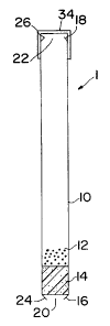
,s The invention will now be described with reference to the
accompanying drawings. FIG. 1 depicts, in a cross-sectional view, one
,a embodiment of the delivery device according to the invention. The device is
,s in prepared form prior to placement in a fluid. Dispensing device 1 is
shown
zo in FIG. 1 to comprise an elongate tubular member 10 with a first end 16 and
a
z, second end 18. Contained within tubular member 10 is a lumen that contains
z2 an active agent formulation 12 and a controller 14. Active agent
formulation
23 12, which can be pan~ticles oil drug, coated drug particles, or "tiny time
pills",
za either alone or with additional carriers, is placed in the tubular member
10.
zs The tubular member 10 comprises a retaining means such as a restriction 24
zs to prevent controller 14 from exiting through the first end 16. The cross-
z~ section of opening 20 is smaller than that of the controller 14. In the
zs embodiment shown in FIG. '1, the retaining means is made by crimping the
zs end 16 of tubular mE~mber 1 ~0. Any convenient means that prohibits
controller
so 14 from exiting through first end 16 while permitting passage of fluid is
s, contemplated by this invention such as, without limitation, a series of
dimples
CA 02289668 1999-11-15
WO 98/51259 PCT/US98/09028
28 or a continuous indentation 30 formed near one or both ends of the tubular
z member 10 as shown in FIGS. 2A and 2B, respectively. In another
s embodiment depicted in FIG. 2C, retaining means 32 is positioned at one or
a both ends of tubular member 10 for preventing controller 14 from exiting
s tubular member 10. The retaining means 32 may be as depicted in FIGS.
s 3A - 3C, however, any element is contemplated that will allow passage of
fluid
without permitting passage of controller 14.
s Second end 18 of tubular member 10 also has a retaining means 26
s for preventing release of controller 14. In the embodiment shown in FIG. 1,
~o the retaining means 26 is prepared by crimping the end 18 of tubular member
10. Preferably, retaining means 26 is configured to facilitate sucking of the
~z active agent formulation 12 into the mouth of the user as shown in FIGS. 4A
,s and 4B. According to another preferred embodiment depicted in FIG. 4C,
,a tubular member 10 gradually tapers to a reduced diameter top portion 36 at
the second end thereof. Side exit openings 38 are provided along tapering
,s region and allow the active agent formulation 12 to be administered to the
patient while preventing controller 14 from exiting tubular member 10. End-
~a cap 34 is placed over the second end 18 of the tubular member 10 prior to
~s use to prevent release of the active agent formulation 12.
zo FIG. 5 shows the delivery device 1 in operation after having been
z~ placed in fluid 30. The first end 16 of the delivery device 1 is placed in
the
zz fluid 30 and the second end 18 of the device is placed in the patient's
mouth
zs after removing cap 34. It is preferable to place the device 1 into the
container
za holding fluid 30 prior to removing cap 34. The patient sips on the second
end
25 18 of the device and an admixture of fluid 30 and active agent formulation
12
Zs is delivered through opening 22 and into the patient's mouth.
z~ FIGS. 6 - 11 depict various embodiments of the improved flow
za controllers 14 of the present invention. Controllers 14 are designed to
allow a
zs predetermined amount of drug to move up through tubular element 10 to the
so point of delivery at the second end 18. The controller 14 is configured to
31 allow liquid to pass either through or around the controller without
allowing
CA 02289668 1999-11-15
WO 98/51259 PCT/US98/09028
11
active agent formulation 12 i:o slip between the sides of controller 14 and
the
z inner wall of tubular member 10 or to leak through the porosity of
controller 14
s towards first end 16. According to another embodiment, it is preferable that
a controller 14 is adapted to accommodate a variation in part sizes such as
the
inner diameter of tubular member 10. This is accomplished through the
s selection of materials for controller and/or by providing controller 14 with
protrusions such as fins, ridges, or rings which act as a seal. The
protrusions
a also create friction or drag between controller 14 and tubular member 10 to
s allow time for the liquid to mix with the active agent formulation 12 after
~o passing though or airound controller 14.
With reference to the drawings, FIG. 6A depicts one embodiment of
~z controller 14 wherein controller 14 is a solid foam plug having an
hourglass
i3 shape. FIG. 2B is also a solid foam plug with a central section 3 having a
,a smaller diameter thin top and bottom sections 5 in order to form a spool
~s design. In each of these embodiments, the upper and lower sections are of a
greater diameter than the middle section and create friction or drag between
w controller 14 and tubular member 10 to allow time for the liquid to mix with
the
~s active agent formulation 12 and act as a seal to prevent any backflow of
~s active agent.
zo FIGS. 7A - 7I7 are cross-views of another embodiment of controller 14
z~ of the present invention. In these embodiments, a spiral ridge 7 runs along
zz the outer surface of cylindrical plug member 9 The spiral ridge 7 may be a
zs continuous spiral or a plurality of parallel ridges and may be fabricated
za separately or together with the cylindrical plug member 9. Spiral ridge 7
may
z5 be of varying thickness and configurations and preferably forms an acute
zs angle with the longivudinal axis of cylindrical plug member 9. For example,
z~ the spiral ridge may be provided a wavy ridge as shown in FIG. 7B in order
to
za provide desired flow characteristics of the liquid as it passes through
zs controller 14 before mixing with the active agent formulation 12.
3o In another embodiment depicted in F1G. 7C, the cylindrical plug
s, member 9 is provided with .a number of horizontal ribs 11 preferably 1 - 4.
CA 02289668 1999-11-15
WO 98/51259 PCT/US98/09028
12
According to this embodiment, cylindrical member 9 may be solid.or hollow as
z seen in FIG. 7D Additionally, the plug member 9 of FIGS. 7A - 7D may be
s provided with flow through channels 13 as depicted in FIG. 7E (top view) so
a that liquid may be drawn up through channels 73 and past controller 14 to
mix
with the active agent formulation 12. The size of the channels 13 is selected
s to allow liquid to be drawn up through controller 14 but not so large as to
allow active agent formulation to pass through controller 14.
s FIGS. 8A and 8B depict another embodiment wherein controller 14
s comprises a number of vertical fins 15, preferably from 2 - 10 rectangular
fins.
~o As seen in FIG. 8B, the fins may be wavy in order to provide for more
turbulent flow of liquid as it passes around the fins 15 before mixing with
the
active agent formulation 12. According to yet another embodiment, controller
13 14 may be a molded finned controller as depicted in FIGS. 8C and 8D formed
from a non-porous, preferably thermoplastic material. As seen in FIG. 8C,
controller 14 comprises circular top 17 from which fins 19 extend downwardly
~s therefrom. Top 17 is a flexible member capable of flexing in a direction
away
1~ from fins 19 so as to allow fluid to pass around top 17 and tubular member
10
~a and may be provided as a separate element. Fins 19 also act as a support
to prevent flexing of top 17 in a direction towards fins 19 so as to prevent
zo active agent formulation from passing around controller 14 and out first
z~ end 16.
zz As seen in FIG. 8C gap d may be provided between some or all of the
zs fins 19 and top 17. Additionally, recesses 21 may be provided along the
edge
za of the fins 19 in order to provide the desired amount of contact between
zs controller 14 and the inner surface of tubular member 10. FIG. 8D depicts
is another embodiment wherein the fins 19 are rounded at the bottom to meet at
z~ a single point. Areas 23 indicate the point of contact between the
controller
za 14 and tubular member 10. FIG. 8E is a top view of the controller of FIG.
8A.
zs FIGS. 9 - 10 depict other embodiments of the controller of the present
so invention which comprise an O - ring 25 or flanged ring of material 27
which
s~ provide controller 14 with a seal against the inner wall of tubular member
10.
CA 02289668 1999-11-15
WO 98/51259 PCT/US98/09028
13
FIG. 9A shows the controller body 31 including annular groove 33 to receive
z O - ring 25 therein. As seen in FIGS. 9B and 9C, O - ring 25 may be a solid
3 or hollow, tubular ring of material. Alternatively, as seen in FIGS. 10A -
10C,
a controller 14 may b~~ formed to include ridges 29 which act to retain
flanged
s ring 27 in position on the controller 14. O - ring 25 and flanged ring 27
s prevent the active agent formulation 12 from passing between controller 14
z and the inner wall of tubular member 10, thus preventing the controller 14
s from getting stuck as it moves within tubular member 10. Further, rings 25
s and 27 allow the outer diameter of controller 14 to vary slightly to
~o accommodate differing dianneters encountered within tubular member 10.
In the embodiment shown in FIGS. 11A - 11 C, controller 14 is provided
~z as a hollow cap. The hollow cap controller 35 may be designed to function
as
~s a controller by itself, or may placed over a hollow or solid cylindrical
plug
member 37 to form the plug cap depicted in FIG. 11 B. Other hollow cap
15 designs are depicted in FIG. 11C wherein cap 35 comprises stepped
~s flange 39 at its open end to provide the desired contact with tubular
member 10.
~a As illustrated in FIG. 12, the controller 14 may be fabricated as a plug
~s of bonded fibers 40. The fibers may be bonded by conventional means such
zo as by intertwining oi~ weaving of the fibers or portions thereof, by the
z~ application of heat, causing at least a portion of the outer surfaces of
the
zz fibers to attach to e;~ch other, and the like. For ease of manufacture, the
zs controller 14 is typically forrned as a cylinder. The plug of bonded fibers
40 is
za compressible and may be manufactured with a diameter slightly greater than
z5 the inner diameter of tubular member 10. When seated within the tubular
zs member 10, the controller 14 will seal to prevent release of discrete units
from
z~ the first end of the tubular member 10, yet permit fluid to enter the lumen
to
zs transport the active agent to the second end and to the patient. The fiber
zs plug is also transportable with the fluid to the second end of the tubular
so member upon application of suction to the second end of the tubular member.
While not shown, the external surfaces of the fiber plug may be modified as
CA 02289668 1999-11-15
WO 98/51259 PCT/US98/09028
14
described herein to provide various configurations for sealing between the
z outer surface of the controller and the inner surface of the tubular member.
s The controller 14 serves as a one-way valve and may be formed from
a porous or non-porous materials. When suction is applied through the tubular
s member 10, the controller 14 is deformed, thereby permitting fluid to flow
s around and/or through the controller 14. When suction is removed, the
controller 14 relaxes and automatically seals the tubular member 10. The
s controller 14 also can move up the elongated tubular member, thereby aiding
s in delivery of the active agent formulation 12. The position of controller
14 in
tubular member 10 serves as an indicator of approximately how much of the
active agent formulation 12 has actually been delivered. The controller
permits the free flow of liquid medium but prohibits passage of the active
~s agent formulation from the device prior to delivery.
~a The controller 14 may be prepared from thermoplastic materials and
15 low or high density foam materials known in the art such as, without
limitation,
ethylene vinyl acetate copolymers and polyolefins such as, for example,
polyethylene, polypropylene and the like, and may be a low density, closed
~s cell foam.
Also, as described above, the controller 14 may be fabricated as a
2o deformable and/or porous plug of bonded fibers, preferably in the shape of
a
2, cylinder, with or without modification of the external surface of the
controller.
2z The controller 14 may be formed as a bonded fiber cylinder of polymeric
2s fibers, such as, polyolefin fibers, with or without a polyester core,
having a
2a fiber diameter of between 0.25 and 0.35 inches and a fiber length of
between
25 0.25 and 0.4 inches, preferably a diameter between 0.280 and 0.310 inches
2s and a length between 0.300 and 0.320 inches. The plug will generally be
fabricated with a diameter that is slightly larger than the inner diameter of
the
is tubular member 10 such that it will be slightly compressed within the
tubular
Zs member 10, but not so tightly compressed that fluid does not flow through
so and/or around the controller upon the application of suction. Examples of
CA 02289668 1999-11-15
WO 98/51259 PCT/US98/09028
useful polyolefins include low density polyethylene (LDPE), high density
z polyethylene (HDPE), ultra high molecular weight polyethylene (UWMW)
s and polypropylene. Presenf:ly preferred fiber materials include
polypropylene
a fibers obtained from American Filtrona Corporation and those having a
s polyester core with a polyolefin sheath obtained from Porex Technologies,
s Fairburn, Georgia. Other materials that may be use to fabricate the fiber
plug controller include polyesters, cellulose acetate, nylon, felt, and
cotton.
s Generally hydrophobic materials are preferred, whether intrinsically
s hydrophobic or modiified to be hydrophobic by the addition of surfactants
and
~o the like. Substantially cylindlrical fiber plugs provide controllers having
the
desirable sealing characteristics set forth herein and permit the flow of
fluid to
~z deliver the active agent formulation as described. Such fiber plugs may be
13 fabricated with or wi~~rhout them surface modifications of the controllers
~a described herein.
~s The active agent itsef~f may be in liquid, solid, or semisolid form. The
~s active agent formulation that contains the active agent may contain
additional
material such as binders, coating materials, or stabilizers such that the
~s formulation is former into one or more discrete units. The units may also
be
~s mixed with sugar granules and flavoring agents to enhance ingestion. The
zo discrete units may be designed in a multitude of ways to provide a specific
z~ drug delivery profile, One embodiment comprises a formulation that is in
zz particulate form. These particulates are generally between about 50 and
z3 2000 p.m in diameter, usually between about 100-500 ~m in diameter. Where
za the particulate has an unpleasant taste, the particulate may be taste
masked
zs by methods that are well known in the art. For example, the particulate may
zs be mixed with effervescent nmaterials (acid and carbonate sources) to form
a
z~ free flowing mixture. The p;~rticulates may be designed to provide
immediate
za delivery of the active: agent, they may be coated to provide for prolonged
is release or delayed pulse reliease of the active agent, or they may be
designed
ao to provide for a combination of immediate, pulsed and/or prolonged delivery
of active agent. Thc~ particulates may be coated with an enteric coating to
CA 02289668 2003-04-14
77223-3
16
1 provide for targeted release of the active agent. !n addition there may be
2 active agent formulations that contain more than one active agent.
s In other embodiments, the active agent may be in the discrete units
a in liquid form contained, for example, within soft gelatin capsules or
s microcapsules, or within a solid oral dosage form. These dosage forms may
s include, matrix or other types of tablets, pellets and elongated tablets
where
the height to diameter ratio exceeds one, capsules, elementary osmotic
a pumps, such as those described in US Patent No. 3,845,770, mini osmotic
s pumps such as those described in US Patent Nos. 3,995,631, 4,034,756,
1o and 4,111,202, and multichamber osmotic systems referred to as push-pull
11 and push-melt osmotic pumps, such as those described in US Patent Nos.
12 4,320,759, 4,327,725, 4,449,983, and 4,765,989.
13
14 It is to be understood that more than one active agent may be
1s incorporated into the active agent formulation in a device of this
invention,
1s and that the use of the term "agent" in no way excludes the use of two or
more such agents.
is The agents can be in various forms, such as soluble and insoluble
1s charged or uncharged molecules, components of molecular complexes or
Zo nonirritating, pharmacologically acceptable salts.
i1 The amount of active agent employed in the delivery device will be that
ii amount necessary to deliver a therapeutically effective amount of the agent
to
is achieve the desired result. In practice, this will vary widely depending
upon
Za the particular agent, the severity of the condition, and the desired
therapeutic
25 effect. However, the device is generally useful for active agents that must
be
is delivered in fairly large doses of from about 100 mg to 5000 mg, usually in
the
range of from about 250 mg to about 2500 mg. However, since the devices
za may also be useful in pediatric patients, doses in the ranges of 25 to 250
mg
is are also contemplated herein.
so Representative materials for forming devices including the elongated
s1 tubular member, the end caps and tabs, include, without limitation, paper,
CA 02289668 1999-11-15
WO 98/51259 PCT/US98/09028
17
plastic such as propylene/styrene copolymers, polypropylene, high density
2 polyethylene, low dE;nsity polyethylene and the like. The devices usually
s have an inner diameter of between about 3 and 8 mm and a wall thickness
a of between about 0.1 and 0.4 mm. The devices are between about 10 and
30 cm in length.
s The fluid that is used for suspending the active agent formulation by
sipping through the active agent formulation chamber is preferably any good-
s tasting liquid including but not limited to water, juice, milk, soda,
coffee, tea
s etc. Care must be t~~ken to ensure compatibility of the fluid with the
active
agent formulation.
11 The above dE~scription has been given for ease of understanding only.
No unnecessary limitations should be understood therefrom, as modifications
js will be obvious to these skilled in the art.