Language selection

Search

Patent 2289859 Summary

Third-party information liability

Some of the information on this Web page has been provided by external sources. The Government of Canada is not responsible for the accuracy, reliability or currency of the information supplied by external sources. Users wishing to rely upon this information should consult directly with the source of the information. Content provided by external sources is not subject to official languages, privacy and accessibility requirements.

Claims and Abstract availability

Any discrepancies in the text and image of the Claims and Abstract are due to differing posting times. Text of the Claims and Abstract are posted:

  • At the time the application is open to public inspection;
  • At the time of issue of the patent (grant).
(12) Patent Application: (11) CA 2289859
(54) English Title: LIQUEFIED PETROLEUM GAS FUEL SYSTEM AND METHOD
(54) French Title: SYSTEME ET PROCEDE D'ALIMENTATION EN GAZ DE PETROLE LIQUEFIE
Status: Deemed Abandoned and Beyond the Period of Reinstatement - Pending Response to Notice of Disregarded Communication
Bibliographic Data
(51) International Patent Classification (IPC):
  • F02M 21/02 (2006.01)
  • B60K 15/03 (2006.01)
  • F02B 43/00 (2006.01)
  • F02D 19/02 (2006.01)
  • F02M 31/20 (2006.01)
(72) Inventors :
  • BENNETT, DAVID E. (United States of America)
(73) Owners :
  • BENNETT TECHNOLOGIES, L.L.C.
(71) Applicants :
  • BENNETT TECHNOLOGIES, L.L.C. (United States of America)
(74) Agent: ROBIC AGENCE PI S.E.C./ROBIC IP AGENCY LP
(74) Associate agent:
(45) Issued:
(86) PCT Filing Date: 1998-05-11
(87) Open to Public Inspection: 1998-11-19
Availability of licence: N/A
Dedicated to the Public: N/A
(25) Language of filing: English

Patent Cooperation Treaty (PCT): Yes
(86) PCT Filing Number: PCT/US1998/009533
(87) International Publication Number: WO 1998051923
(85) National Entry: 1999-11-12

(30) Application Priority Data:
Application No. Country/Territory Date
08/855,217 (United States of America) 1997-05-13

Abstracts

English Abstract


A fuel supply system and method for reducing the pressure in the fuel tank for
a liquefied petroleum gas fuel supply system in which fuel is returned to the
tank. Return fuel is cooled by heat transfer devices in the return line in
line and in the tank.


French Abstract

Système et procédé d'alimentation en carburant permettant d'abaisser la pression à l'intérieur d'un réservoir à carburant. Ce système convient pour une alimentation en gaz de pétrole liquéfié, dans lequel le carburant est renvoyé au réservoir. Le carburant de retour est refroidi par des dispositifs de transfert thermique disposés dans la conduite de retour, dans la conduite d'alimentation et dans le réservoir.

Claims

Note: Claims are shown in the official language in which they were submitted.

5
WHAT IS CLAIMED IS:
1. A fuel supply system for providing liquefied petroleum gas to an
internal combustion engine, comprising:
(a) a plurality of fuel injectors in fluid communication with a fuel supply
line communicating with a fuel tank;
(b) a fuel return line; and
(c) a condenser in fluid communication with said fuel return line,
positioned in said fuel tank, and comprising:
(i) an elongated body having a passage therethrough for returning
return fuel to said fuel tank; and
(ii) a plurality of vent holes spaced along a length of said body
and communicating with said passage;
(iii) said vent holes being sloped relative to horizontal along said
length such that gaseous fuel will tend to first exit vent holes toward a
distal end of said passage.
2. A fuel supply system according to claim 1, wherein said condenser
has external fins for transferring heat from the return fuel.
3. A fuel supply system according to claim 1 wherein said condenser
has internal fins for transferring heat from the return fuel.
4. A fuel supply system according to claim 1, wherein condenser is
mounted proximate a bottom of said fuel tank.,
5. A fuel supply system according to claim 1, wherein said passage is a
straight passage beginning at a proximal end of said body and ending at a
distal end.
6. A fuel supply system according to claim 5, wherein said distal end of
said body is raised relative to said proximal end, thereby sloping said vent
holes.
7. A fuel supply system according to claim 1, wherein said vent holes
are at a constant height relative to said body and passage.
8. A fuel supply system according to claim 1, wherein said vent holes
are about between 0.030 and 0.080 inches in diameter.

6
9. A fuel supply system according to claim 1, wherein the total area of
said vent holes is greater than twice an internal cross-sectional area of said
fuel
return line.
10. A fuel supply system according to claim 1, wherein said vent holes
are arranged on opposite sides of said body proximate a middle height of said
passage.
11. An apparatus for condensing return fuel in a fuel tank, comprising:
(a) an elongated body having a passage therethrough in fluid
communication with a fuel return line; and
(b) a plurality of vent holes spaced along a length of said body and
communicating with said passage;
(c) said passage and said vent holes being constructed and arranged such
that gaseous fuel will tend to first exit vent holes toward a distal end of
said
passage.
12. An apparatus according to claim 11, further including external fins
extending longitudinally along said body, arranged relative to said vent holes
such
that gaseous bubbles exiting said vent holes will travel along said fins prior
to rising
upwardly in the tank.
13. An apparatus according to claim 11, further including internal fins
extending radially into said passage from said body.
14. An apparatus according to claim 11, wherein said passage is a straight
passage beginning at a proximal end of said body and ending at a distal end.
15. An apparatus according to claim 14, wherein said distal end of said
body is raised relative to said proximal end, thereby sloping said vent holes.
16. An apparatus according to claim 11, wherein said vent holes are at a
constant height relative to said body and passage.
17. An apparatus according to claim 11, wherein said vent holes are
about between 0.030 and 0.080 inches in diameter.

7
18. An apparatus according to claim 11, wherein the total area of said
vent holes is greater than twice an internal cross-sectional area of said fuel
return
line.
19. An apparatus according to claim 11, wherein said vent holes are
arranged on opposite sides of said body proximate a middle height of said
passage.

Description

Note: Descriptions are shown in the official language in which they were submitted.


CA 02289859 1999-11-12
1 . . .. ..
CONDENSER FOR FUEL INJECTION SYSTEM
Incorporation by Reference
Applicant's U.S. Patent Nos. 5,291,869; 5,325,838; and 5,423,303 are
incorporated herein by reference.
Field of the Invention
This invention relates to a liquefied petroleum gas fuel injection system, and
more particularly to a system and method for cooling return fuel in such
systems.
Background of the Invention
Liquefied petroleum gas ("LPG") fuel supply systems are known, for
example as shown in Applicant's U.S. Patent Nos. 5,291,869; 5,325,838; and
5,423,303. Such systems typically include a number of specialized fuel
injectors
which receive fuel from a high pressure tank. A fuel rail connected in-line
with a
series of injectors is often employed to deliver supply fuel to the injectors.
In many
systems, uninfected fuel is returned to the fuel tank. This is generally done
to keep
the supply fuel as cool as possible, particularly where it is intended to
inject LPG in
liquid rather than gaseous form.
One approach to injecting LPG without permitting it to vaporize is to pump
high volumes of supply and return fuel. In this way, the supply fuel spends
very
little time near the heated engine compartment where it can vaporize. Another
approach is to employ a refrigeration cycle as described in the Applicant's
patents
identified above. The evaporation of return fu~l is used to cool supply fuel,
thereby
maintaining it in liquid form.
A problem with returning vaporized LPG to the fuel tank is that it can
increase tank pressure substantially above the vapor pressure of the liquid in
the
tank. If the vapor does not condense before the pressure limit of the tank is
exceeded, the pressure relief valve will release LPG vapor to the atmosphere.
This
is both unsafe and environmentally undesirable.
What has been needed is a way to cool return fuel in LPG systems so as to
reduce the high fuel tank pressures which can occur.
Summary of the Invention
According to the present invention, an LPG fuel supply system and method
are provided.
In one aspect of the system, the LPG system includes a plurality of fuel
injectors operably connected to a fuel rail. The fuel rail is in fluid
communication

CA 02289859 1999-11-12
WO 98151923 PCT/US98/09533
2
with fuel supply and return lines. Both the fuel rail and injectors comprise
an
arrangement for cooling supply fuel with return fuel. A condenser in the
return line
cools return fuel.
In another aspect of the invention, the LPG fuel supply system comprises a
plurality of fuel injectors in fluid communication with fuel supply and return
lines.
The fuel return line includes a mechanism for cooling return fuel.
In the method of the present invention, a liquefied petroleum gas fuel supply
system is provided, comprising a plurality of fuel injectors in fluid
communication
with a fuel supply line and fuel return line. Vaporous fuel is produced in the
fuel
I 0 return line by the absorption of heat. The vaporous fuel is then cooled in
the fuel
return line prior to introducing it into the fuel in the fuel tank.
These and other advantages and features of novelty which characterize the
W vention are pointed out with particularity in the claims annexed hereto.
However,
for a better understanding of the invention and its advantages, reference
should be
I S made to the drawings which form a further part hereof, and to the
accompanying
descriptive matter in which there is illustrated and described a preferred
embodiment
of the invention.
Brief Description of the Figures
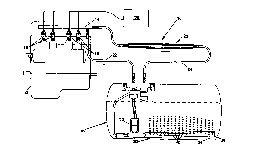
20 Fig. 1 is a schematic diagram of a system according to the present
invention;
and
Fig. 2 is a cross-sectional view of condensers according to the present
invention.
25 Detailed Description of Preferred Embodiment
Referring now to the drawings, wherein like numerals designate like parts
throughout the figures, a fuel supply system 10 for providing LPG to an
internal
combustion engine 12 is shown. Applicant's U.S. Patent Nos. 5,291,869 ("'869
patent"), "LIQUEFIED PETROLEUM GAS FUEL SUPPLY SYSTEM," 5,325,838
30 ("'838 patent"), "LIQUEFIED PETROLEUM GAS FUEL INJECTOR," and
5,423,303 ("'303 patent"), "FUEL RAIL FOR INTERNAL COMBUSTION
ENGINE" are also incorporated by reference and will be referred to herein as
appropriate.
System 10 includes a fuel rail 14 which delivers fuel to a plurality of fuel
35 injectors 16. Although a fuel rail is shown in the preferred embodiment,
one is not
necessary within the principles of the invention. For example, separate supply
lines
branching from a main supply line could deliver fuel to each injector in
parallel. -
_._. , _.... .. ..~.~ ...... r

CA 02289859 1999-11-12
.. ..
3 . .. .. ..
In the preferred embodiment, both fuel rail 14 and injector 16 include
arrangements for cooling supply fuel with return fuel, such as those described
in the
'869 patent generally, and more specifically in the '303 patent for the fuel
rail and
the '838 patent for the fuel injector. These arrangements involve evaporating
return
fuel in close proximity to supply fuel so as to extract heat from the supply
fuel. In
this way, supply LPG is maintained in liquid form when injected. It is not
necessary, however, for the fuel rail or injectors to have such a
refrigeration cycle, as
there are other ways in which liquid LPG at injection can be achieved.
The main problem the present invention addresses is the high tank pressures
which can result when heated LPG is returned to the fuel tank 18. Under the
present
regulations in the United States, the maximum allowable tank pressure is 312
psi. A
pressure relief valve (not shown) would be opened if this maximum pressure is
reached.
Return fuel is heated in its passage through the engine compartment by the
engine itself. It can also be heated if a refrigeration cycle such as those in
the
preferred embodiment is employed. If the return line is routed under the
chassis,
engine, transmission, exhaust and radiator heat will also tend to be absorbed
there.
The problem is most pronounced at high engine and ambient temperatures and at
low fuel levels.
Referring to Figs. l and 2, a system and method for addressing this problem
will be described. In addition to the fuel injectors 16 and fuel rail 14
described
above, system 10 includes fuel pump 20, supply line 22 and return line 24. As
is
generally the case, an engine control unit 26 controls injectors 16.
Return fuel is cooled in the preferred embodiment by in-line 28 and in-tank
30 condensers in return line 24. As shown in Fig. 2, condensers 28, 30 have
external
32 and internal 34 fins to aid heat transfer. They are made of extruded
aluminum.
In-line condenser 28, and as much of return line 24 as possible, are
preferably located away from the hot underchassis. Cooler air can then assist
in
extracting heat from return fuel in condenser 28. If necessary, through
ducting or
otherwise, air can be forced across external fins 32 to further increase
cooling. It
rnay also be necessary to thermally insulate return line 24, as for example by
surrounding with foam rubber.
In-tank condenser 30 is immersed in fuel tank 18 at a terminal end of return
line 24. Condenser 30 is placed below the fuel level in the tank so heat can
be
transferred to the liquid fuel. It is preferably mounted at the bottom of tank
18 to
maximize exposure. Condenser 30 is elevated by legs 36 at its distal end 38
and has
a plurality of vent holes 40 from which return fuel enters the fuel in tank
18. By this
arrangement, gaseous fuel tends to be cooled along the entire length of
condenser 30

CA 02289859 1999-11-12
WO 98/51923 PCT/US98/09533
4 _
before exiting near distal end 38. Spreading vent holes across tank 18 reduces
the
localized heat which would otherwise occur. Vent holes 40 are also preferably
small, on the order of .03-.08 inches diameter, preferably .06 inches, to
create
smaller bubbles which will condense faster. The total flow area through vent
holes
40 is preferably twice the cross-sectional area of return line 24 to minimize
back
pressure. While vent holes 40 are shown at approximately the horizontal
quadrant of
condenser 30, it may be preferable to position them lower to improve cooling.
The principle of cooling with a liquid could also be applied, for example, by
cooling in-line with water or another liquid other than fuel.
Where both of the in-line 28 and in-tank 30 condenser are employed as
described herein, cooling on the order of 200-500 watts or higher can be
obtained.
Whether one or both will be needed depends on the cooling needs of the
particular
system. The type and number of heat transfer devices and their size, shape and
arrangement can also be varied within the principles of the invention.

Representative Drawing
A single figure which represents the drawing illustrating the invention.
Administrative Status

2024-08-01:As part of the Next Generation Patents (NGP) transition, the Canadian Patents Database (CPD) now contains a more detailed Event History, which replicates the Event Log of our new back-office solution.

Please note that "Inactive:" events refers to events no longer in use in our new back-office solution.

For a clearer understanding of the status of the application/patent presented on this page, the site Disclaimer , as well as the definitions for Patent , Event History , Maintenance Fee  and Payment History  should be consulted.

Event History

Description Date
Inactive: IPC from MCD 2006-03-12
Application Not Reinstated by Deadline 2004-05-11
Inactive: Dead - RFE never made 2004-05-11
Deemed Abandoned - Failure to Respond to Maintenance Fee Notice 2004-05-11
Inactive: Abandon-RFE+Late fee unpaid-Correspondence sent 2003-05-12
Letter Sent 2000-11-23
Reinstatement Requirements Deemed Compliant for All Abandonment Reasons 2000-11-10
Deemed Abandoned - Failure to Respond to Maintenance Fee Notice 2000-05-11
Letter Sent 2000-05-05
Inactive: Single transfer 2000-03-28
Inactive: Cover page published 2000-01-12
Inactive: IPC assigned 2000-01-10
Inactive: First IPC assigned 2000-01-10
Inactive: Courtesy letter - Evidence 1999-12-21
Inactive: Notice - National entry - No RFE 1999-12-14
Application Received - PCT 1999-12-13
Application Published (Open to Public Inspection) 1998-11-19

Abandonment History

Abandonment Date Reason Reinstatement Date
2004-05-11
2000-05-11

Maintenance Fee

The last payment was received on 2003-04-03

Note : If the full payment has not been received on or before the date indicated, a further fee may be required which may be one of the following

  • the reinstatement fee;
  • the late payment fee; or
  • additional fee to reverse deemed expiry.

Please refer to the CIPO Patent Fees web page to see all current fee amounts.

Fee History

Fee Type Anniversary Year Due Date Paid Date
Basic national fee - standard 1999-11-12
Registration of a document 2000-03-28
MF (application, 2nd anniv.) - standard 02 2000-05-11 2000-11-10
Reinstatement 2000-11-10
MF (application, 3rd anniv.) - standard 03 2001-05-11 2001-04-04
MF (application, 4th anniv.) - standard 04 2002-05-13 2002-04-02
MF (application, 5th anniv.) - standard 05 2003-05-12 2003-04-03
Owners on Record

Note: Records showing the ownership history in alphabetical order.

Current Owners on Record
BENNETT TECHNOLOGIES, L.L.C.
Past Owners on Record
DAVID E. BENNETT
Past Owners that do not appear in the "Owners on Record" listing will appear in other documentation within the application.
Documents

To view selected files, please enter reCAPTCHA code :


To view images, click a link in the Document Description column. To download the documents, select one or more checkboxes in the first column and then click the "Download Selected in PDF format (Zip Archive)" or the "Download Selected as Single PDF" button.

List of published and non-published patent-specific documents on the CPD .

If you have any difficulty accessing content, you can call the Client Service Centre at 1-866-997-1936 or send them an e-mail at CIPO Client Service Centre.


Document
Description 
Date
(yyyy-mm-dd) 
Number of pages   Size of Image (KB) 
Representative drawing 2000-01-12 1 13
Claims 1999-11-12 3 90
Drawings 1999-11-12 2 46
Abstract 1999-11-12 1 51
Description 1999-11-12 4 200
Cover Page 2000-01-12 1 39
Notice of National Entry 1999-12-14 1 193
Reminder of maintenance fee due 2000-01-12 1 113
Courtesy - Certificate of registration (related document(s)) 2000-05-05 1 113
Courtesy - Abandonment Letter (Maintenance Fee) 2000-06-08 1 184
Notice of Reinstatement 2000-11-23 1 171
Reminder - Request for Examination 2003-01-14 1 112
Courtesy - Abandonment Letter (Request for Examination) 2003-07-21 1 165
Courtesy - Abandonment Letter (Maintenance Fee) 2004-07-06 1 175
Correspondence 1999-12-14 1 14
PCT 1999-11-12 14 520