Sélection de la langue

Search

Sommaire du brevet 2289859 

Énoncé de désistement de responsabilité concernant l'information provenant de tiers

Une partie des informations de ce site Web a été fournie par des sources externes. Le gouvernement du Canada n'assume aucune responsabilité concernant la précision, l'actualité ou la fiabilité des informations fournies par les sources externes. Les utilisateurs qui désirent employer cette information devraient consulter directement la source des informations. Le contenu fourni par les sources externes n'est pas assujetti aux exigences sur les langues officielles, la protection des renseignements personnels et l'accessibilité.

Disponibilité de l'Abrégé et des Revendications

L'apparition de différences dans le texte et l'image des Revendications et de l'Abrégé dépend du moment auquel le document est publié. Les textes des Revendications et de l'Abrégé sont affichés :

  • lorsque la demande peut être examinée par le public;
  • lorsque le brevet est émis (délivrance).
(12) Demande de brevet: (11) CA 2289859
(54) Titre français: SYSTEME ET PROCEDE D'ALIMENTATION EN GAZ DE PETROLE LIQUEFIE
(54) Titre anglais: LIQUEFIED PETROLEUM GAS FUEL SYSTEM AND METHOD
Statut: Réputée abandonnée et au-delà du délai pour le rétablissement - en attente de la réponse à l’avis de communication rejetée
Données bibliographiques
(51) Classification internationale des brevets (CIB):
  • F02M 21/02 (2006.01)
  • B60K 15/03 (2006.01)
  • F02B 43/00 (2006.01)
  • F02D 19/02 (2006.01)
  • F02M 31/20 (2006.01)
(72) Inventeurs :
  • BENNETT, DAVID E. (Etats-Unis d'Amérique)
(73) Titulaires :
  • BENNETT TECHNOLOGIES, L.L.C.
(71) Demandeurs :
  • BENNETT TECHNOLOGIES, L.L.C. (Etats-Unis d'Amérique)
(74) Agent: ROBIC AGENCE PI S.E.C./ROBIC IP AGENCY LP
(74) Co-agent:
(45) Délivré:
(86) Date de dépôt PCT: 1998-05-11
(87) Mise à la disponibilité du public: 1998-11-19
Licence disponible: S.O.
Cédé au domaine public: S.O.
(25) Langue des documents déposés: Anglais

Traité de coopération en matière de brevets (PCT): Oui
(86) Numéro de la demande PCT: PCT/US1998/009533
(87) Numéro de publication internationale PCT: WO 1998051923
(85) Entrée nationale: 1999-11-12

(30) Données de priorité de la demande:
Numéro de la demande Pays / territoire Date
08/855,217 (Etats-Unis d'Amérique) 1997-05-13

Abrégés

Abrégé français

Système et procédé d'alimentation en carburant permettant d'abaisser la pression à l'intérieur d'un réservoir à carburant. Ce système convient pour une alimentation en gaz de pétrole liquéfié, dans lequel le carburant est renvoyé au réservoir. Le carburant de retour est refroidi par des dispositifs de transfert thermique disposés dans la conduite de retour, dans la conduite d'alimentation et dans le réservoir.


Abrégé anglais


A fuel supply system and method for reducing the pressure in the fuel tank for
a liquefied petroleum gas fuel supply system in which fuel is returned to the
tank. Return fuel is cooled by heat transfer devices in the return line in
line and in the tank.

Revendications

Note : Les revendications sont présentées dans la langue officielle dans laquelle elles ont été soumises.


5
WHAT IS CLAIMED IS:
1. A fuel supply system for providing liquefied petroleum gas to an
internal combustion engine, comprising:
(a) a plurality of fuel injectors in fluid communication with a fuel supply
line communicating with a fuel tank;
(b) a fuel return line; and
(c) a condenser in fluid communication with said fuel return line,
positioned in said fuel tank, and comprising:
(i) an elongated body having a passage therethrough for returning
return fuel to said fuel tank; and
(ii) a plurality of vent holes spaced along a length of said body
and communicating with said passage;
(iii) said vent holes being sloped relative to horizontal along said
length such that gaseous fuel will tend to first exit vent holes toward a
distal end of said passage.
2. A fuel supply system according to claim 1, wherein said condenser
has external fins for transferring heat from the return fuel.
3. A fuel supply system according to claim 1 wherein said condenser
has internal fins for transferring heat from the return fuel.
4. A fuel supply system according to claim 1, wherein condenser is
mounted proximate a bottom of said fuel tank.,
5. A fuel supply system according to claim 1, wherein said passage is a
straight passage beginning at a proximal end of said body and ending at a
distal end.
6. A fuel supply system according to claim 5, wherein said distal end of
said body is raised relative to said proximal end, thereby sloping said vent
holes.
7. A fuel supply system according to claim 1, wherein said vent holes
are at a constant height relative to said body and passage.
8. A fuel supply system according to claim 1, wherein said vent holes
are about between 0.030 and 0.080 inches in diameter.

6
9. A fuel supply system according to claim 1, wherein the total area of
said vent holes is greater than twice an internal cross-sectional area of said
fuel
return line.
10. A fuel supply system according to claim 1, wherein said vent holes
are arranged on opposite sides of said body proximate a middle height of said
passage.
11. An apparatus for condensing return fuel in a fuel tank, comprising:
(a) an elongated body having a passage therethrough in fluid
communication with a fuel return line; and
(b) a plurality of vent holes spaced along a length of said body and
communicating with said passage;
(c) said passage and said vent holes being constructed and arranged such
that gaseous fuel will tend to first exit vent holes toward a distal end of
said
passage.
12. An apparatus according to claim 11, further including external fins
extending longitudinally along said body, arranged relative to said vent holes
such
that gaseous bubbles exiting said vent holes will travel along said fins prior
to rising
upwardly in the tank.
13. An apparatus according to claim 11, further including internal fins
extending radially into said passage from said body.
14. An apparatus according to claim 11, wherein said passage is a straight
passage beginning at a proximal end of said body and ending at a distal end.
15. An apparatus according to claim 14, wherein said distal end of said
body is raised relative to said proximal end, thereby sloping said vent holes.
16. An apparatus according to claim 11, wherein said vent holes are at a
constant height relative to said body and passage.
17. An apparatus according to claim 11, wherein said vent holes are
about between 0.030 and 0.080 inches in diameter.

7
18. An apparatus according to claim 11, wherein the total area of said
vent holes is greater than twice an internal cross-sectional area of said fuel
return
line.
19. An apparatus according to claim 11, wherein said vent holes are
arranged on opposite sides of said body proximate a middle height of said
passage.

Description

Note : Les descriptions sont présentées dans la langue officielle dans laquelle elles ont été soumises.

CA 02289859 1999-11-12
1 . . .. ..
CONDENSER FOR FUEL INJECTION SYSTEM
Incorporation by Reference
Applicant's U.S. Patent Nos. 5,291,869; 5,325,838; and 5,423,303 are
incorporated herein by reference.
Field of the Invention
This invention relates to a liquefied petroleum gas fuel injection system, and
more particularly to a system and method for cooling return fuel in such
systems.
Background of the Invention
Liquefied petroleum gas ("LPG") fuel supply systems are known, for
example as shown in Applicant's U.S. Patent Nos. 5,291,869; 5,325,838; and
5,423,303. Such systems typically include a number of specialized fuel
injectors
which receive fuel from a high pressure tank. A fuel rail connected in-line
with a
series of injectors is often employed to deliver supply fuel to the injectors.
In many
systems, uninfected fuel is returned to the fuel tank. This is generally done
to keep
the supply fuel as cool as possible, particularly where it is intended to
inject LPG in
liquid rather than gaseous form.
One approach to injecting LPG without permitting it to vaporize is to pump
high volumes of supply and return fuel. In this way, the supply fuel spends
very
little time near the heated engine compartment where it can vaporize. Another
approach is to employ a refrigeration cycle as described in the Applicant's
patents
identified above. The evaporation of return fu~l is used to cool supply fuel,
thereby
maintaining it in liquid form.
A problem with returning vaporized LPG to the fuel tank is that it can
increase tank pressure substantially above the vapor pressure of the liquid in
the
tank. If the vapor does not condense before the pressure limit of the tank is
exceeded, the pressure relief valve will release LPG vapor to the atmosphere.
This
is both unsafe and environmentally undesirable.
What has been needed is a way to cool return fuel in LPG systems so as to
reduce the high fuel tank pressures which can occur.
Summary of the Invention
According to the present invention, an LPG fuel supply system and method
are provided.
In one aspect of the system, the LPG system includes a plurality of fuel
injectors operably connected to a fuel rail. The fuel rail is in fluid
communication

CA 02289859 1999-11-12
WO 98151923 PCT/US98/09533
2
with fuel supply and return lines. Both the fuel rail and injectors comprise
an
arrangement for cooling supply fuel with return fuel. A condenser in the
return line
cools return fuel.
In another aspect of the invention, the LPG fuel supply system comprises a
plurality of fuel injectors in fluid communication with fuel supply and return
lines.
The fuel return line includes a mechanism for cooling return fuel.
In the method of the present invention, a liquefied petroleum gas fuel supply
system is provided, comprising a plurality of fuel injectors in fluid
communication
with a fuel supply line and fuel return line. Vaporous fuel is produced in the
fuel
I 0 return line by the absorption of heat. The vaporous fuel is then cooled in
the fuel
return line prior to introducing it into the fuel in the fuel tank.
These and other advantages and features of novelty which characterize the
W vention are pointed out with particularity in the claims annexed hereto.
However,
for a better understanding of the invention and its advantages, reference
should be
I S made to the drawings which form a further part hereof, and to the
accompanying
descriptive matter in which there is illustrated and described a preferred
embodiment
of the invention.
Brief Description of the Figures
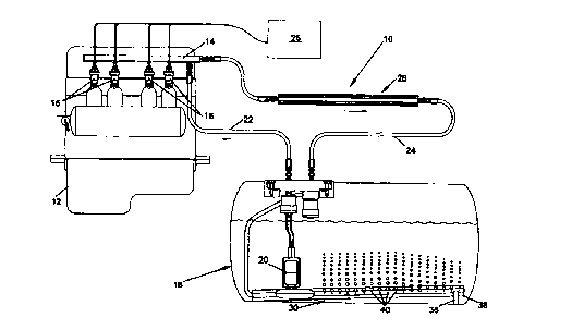
20 Fig. 1 is a schematic diagram of a system according to the present
invention;
and
Fig. 2 is a cross-sectional view of condensers according to the present
invention.
25 Detailed Description of Preferred Embodiment
Referring now to the drawings, wherein like numerals designate like parts
throughout the figures, a fuel supply system 10 for providing LPG to an
internal
combustion engine 12 is shown. Applicant's U.S. Patent Nos. 5,291,869 ("'869
patent"), "LIQUEFIED PETROLEUM GAS FUEL SUPPLY SYSTEM," 5,325,838
30 ("'838 patent"), "LIQUEFIED PETROLEUM GAS FUEL INJECTOR," and
5,423,303 ("'303 patent"), "FUEL RAIL FOR INTERNAL COMBUSTION
ENGINE" are also incorporated by reference and will be referred to herein as
appropriate.
System 10 includes a fuel rail 14 which delivers fuel to a plurality of fuel
35 injectors 16. Although a fuel rail is shown in the preferred embodiment,
one is not
necessary within the principles of the invention. For example, separate supply
lines
branching from a main supply line could deliver fuel to each injector in
parallel. -
_._. , _.... .. ..~.~ ...... r

CA 02289859 1999-11-12
.. ..
3 . .. .. ..
In the preferred embodiment, both fuel rail 14 and injector 16 include
arrangements for cooling supply fuel with return fuel, such as those described
in the
'869 patent generally, and more specifically in the '303 patent for the fuel
rail and
the '838 patent for the fuel injector. These arrangements involve evaporating
return
fuel in close proximity to supply fuel so as to extract heat from the supply
fuel. In
this way, supply LPG is maintained in liquid form when injected. It is not
necessary, however, for the fuel rail or injectors to have such a
refrigeration cycle, as
there are other ways in which liquid LPG at injection can be achieved.
The main problem the present invention addresses is the high tank pressures
which can result when heated LPG is returned to the fuel tank 18. Under the
present
regulations in the United States, the maximum allowable tank pressure is 312
psi. A
pressure relief valve (not shown) would be opened if this maximum pressure is
reached.
Return fuel is heated in its passage through the engine compartment by the
engine itself. It can also be heated if a refrigeration cycle such as those in
the
preferred embodiment is employed. If the return line is routed under the
chassis,
engine, transmission, exhaust and radiator heat will also tend to be absorbed
there.
The problem is most pronounced at high engine and ambient temperatures and at
low fuel levels.
Referring to Figs. l and 2, a system and method for addressing this problem
will be described. In addition to the fuel injectors 16 and fuel rail 14
described
above, system 10 includes fuel pump 20, supply line 22 and return line 24. As
is
generally the case, an engine control unit 26 controls injectors 16.
Return fuel is cooled in the preferred embodiment by in-line 28 and in-tank
30 condensers in return line 24. As shown in Fig. 2, condensers 28, 30 have
external
32 and internal 34 fins to aid heat transfer. They are made of extruded
aluminum.
In-line condenser 28, and as much of return line 24 as possible, are
preferably located away from the hot underchassis. Cooler air can then assist
in
extracting heat from return fuel in condenser 28. If necessary, through
ducting or
otherwise, air can be forced across external fins 32 to further increase
cooling. It
rnay also be necessary to thermally insulate return line 24, as for example by
surrounding with foam rubber.
In-tank condenser 30 is immersed in fuel tank 18 at a terminal end of return
line 24. Condenser 30 is placed below the fuel level in the tank so heat can
be
transferred to the liquid fuel. It is preferably mounted at the bottom of tank
18 to
maximize exposure. Condenser 30 is elevated by legs 36 at its distal end 38
and has
a plurality of vent holes 40 from which return fuel enters the fuel in tank
18. By this
arrangement, gaseous fuel tends to be cooled along the entire length of
condenser 30

CA 02289859 1999-11-12
WO 98/51923 PCT/US98/09533
4 _
before exiting near distal end 38. Spreading vent holes across tank 18 reduces
the
localized heat which would otherwise occur. Vent holes 40 are also preferably
small, on the order of .03-.08 inches diameter, preferably .06 inches, to
create
smaller bubbles which will condense faster. The total flow area through vent
holes
40 is preferably twice the cross-sectional area of return line 24 to minimize
back
pressure. While vent holes 40 are shown at approximately the horizontal
quadrant of
condenser 30, it may be preferable to position them lower to improve cooling.
The principle of cooling with a liquid could also be applied, for example, by
cooling in-line with water or another liquid other than fuel.
Where both of the in-line 28 and in-tank 30 condenser are employed as
described herein, cooling on the order of 200-500 watts or higher can be
obtained.
Whether one or both will be needed depends on the cooling needs of the
particular
system. The type and number of heat transfer devices and their size, shape and
arrangement can also be varied within the principles of the invention.

Dessin représentatif
Une figure unique qui représente un dessin illustrant l'invention.
États administratifs

2024-08-01 : Dans le cadre de la transition vers les Brevets de nouvelle génération (BNG), la base de données sur les brevets canadiens (BDBC) contient désormais un Historique d'événement plus détaillé, qui reproduit le Journal des événements de notre nouvelle solution interne.

Veuillez noter que les événements débutant par « Inactive : » se réfèrent à des événements qui ne sont plus utilisés dans notre nouvelle solution interne.

Pour une meilleure compréhension de l'état de la demande ou brevet qui figure sur cette page, la rubrique Mise en garde , et les descriptions de Brevet , Historique d'événement , Taxes périodiques et Historique des paiements devraient être consultées.

Historique d'événement

Description Date
Inactive : CIB de MCD 2006-03-12
Demande non rétablie avant l'échéance 2004-05-11
Inactive : Morte - RE jamais faite 2004-05-11
Réputée abandonnée - omission de répondre à un avis sur les taxes pour le maintien en état 2004-05-11
Inactive : Abandon.-RE+surtaxe impayées-Corr envoyée 2003-05-12
Lettre envoyée 2000-11-23
Exigences de rétablissement - réputé conforme pour tous les motifs d'abandon 2000-11-10
Réputée abandonnée - omission de répondre à un avis sur les taxes pour le maintien en état 2000-05-11
Lettre envoyée 2000-05-05
Inactive : Transfert individuel 2000-03-28
Inactive : Page couverture publiée 2000-01-12
Inactive : CIB attribuée 2000-01-10
Inactive : CIB en 1re position 2000-01-10
Inactive : Lettre de courtoisie - Preuve 1999-12-21
Inactive : Notice - Entrée phase nat. - Pas de RE 1999-12-14
Demande reçue - PCT 1999-12-13
Demande publiée (accessible au public) 1998-11-19

Historique d'abandonnement

Date d'abandonnement Raison Date de rétablissement
2004-05-11
2000-05-11

Taxes périodiques

Le dernier paiement a été reçu le 2003-04-03

Avis : Si le paiement en totalité n'a pas été reçu au plus tard à la date indiquée, une taxe supplémentaire peut être imposée, soit une des taxes suivantes :

  • taxe de rétablissement ;
  • taxe pour paiement en souffrance ; ou
  • taxe additionnelle pour le renversement d'une péremption réputée.

Veuillez vous référer à la page web des taxes sur les brevets de l'OPIC pour voir tous les montants actuels des taxes.

Historique des taxes

Type de taxes Anniversaire Échéance Date payée
Taxe nationale de base - générale 1999-11-12
Enregistrement d'un document 2000-03-28
TM (demande, 2e anniv.) - générale 02 2000-05-11 2000-11-10
Rétablissement 2000-11-10
TM (demande, 3e anniv.) - générale 03 2001-05-11 2001-04-04
TM (demande, 4e anniv.) - générale 04 2002-05-13 2002-04-02
TM (demande, 5e anniv.) - générale 05 2003-05-12 2003-04-03
Titulaires au dossier

Les titulaires actuels et antérieures au dossier sont affichés en ordre alphabétique.

Titulaires actuels au dossier
BENNETT TECHNOLOGIES, L.L.C.
Titulaires antérieures au dossier
DAVID E. BENNETT
Les propriétaires antérieurs qui ne figurent pas dans la liste des « Propriétaires au dossier » apparaîtront dans d'autres documents au dossier.
Documents

Pour visionner les fichiers sélectionnés, entrer le code reCAPTCHA :


Pour visualiser une image, cliquer sur un lien dans la colonne description du document. Pour télécharger l'image (les images), cliquer l'une ou plusieurs cases à cocher dans la première colonne et ensuite cliquer sur le bouton "Télécharger sélection en format PDF (archive Zip)" ou le bouton "Télécharger sélection (en un fichier PDF fusionné)".

Liste des documents de brevet publiés et non publiés sur la BDBC .

Si vous avez des difficultés à accéder au contenu, veuillez communiquer avec le Centre de services à la clientèle au 1-866-997-1936, ou envoyer un courriel au Centre de service à la clientèle de l'OPIC.


Description du
Document 
Date
(aaaa-mm-jj) 
Nombre de pages   Taille de l'image (Ko) 
Dessin représentatif 2000-01-12 1 13
Revendications 1999-11-12 3 90
Dessins 1999-11-12 2 46
Abrégé 1999-11-12 1 51
Description 1999-11-12 4 200
Page couverture 2000-01-12 1 39
Avis d'entree dans la phase nationale 1999-12-14 1 193
Rappel de taxe de maintien due 2000-01-12 1 113
Courtoisie - Certificat d'enregistrement (document(s) connexe(s)) 2000-05-05 1 113
Courtoisie - Lettre d'abandon (taxe de maintien en état) 2000-06-08 1 184
Avis de retablissement 2000-11-23 1 171
Rappel - requête d'examen 2003-01-14 1 112
Courtoisie - Lettre d'abandon (requête d'examen) 2003-07-21 1 165
Courtoisie - Lettre d'abandon (taxe de maintien en état) 2004-07-06 1 175
Correspondance 1999-12-14 1 14
PCT 1999-11-12 14 520