Language selection

Search

Patent 2290295 Summary

Third-party information liability

Some of the information on this Web page has been provided by external sources. The Government of Canada is not responsible for the accuracy, reliability or currency of the information supplied by external sources. Users wishing to rely upon this information should consult directly with the source of the information. Content provided by external sources is not subject to official languages, privacy and accessibility requirements.

Claims and Abstract availability

Any discrepancies in the text and image of the Claims and Abstract are due to differing posting times. Text of the Claims and Abstract are posted:

  • At the time the application is open to public inspection;
  • At the time of issue of the patent (grant).
(12) Patent Application: (11) CA 2290295
(54) English Title: SPORT PROTECTION EYEWEAR
(54) French Title: LUNETTES PROTECTRICES POUR LE SPORT
Status: Deemed Abandoned and Beyond the Period of Reinstatement - Pending Response to Notice of Disregarded Communication
Bibliographic Data
Abstracts

English Abstract


Eyewear comprising a frame having top, bottom and opposite
sides defining a lens opening, each opposite side having lens engaging
means, and a lens adapted to be removably attached to the frame to
substantially cover the lens opening. The lens posseses translucent front
and rear faces, opposite first and second side ends, and a first and second
lens locking portions. The first lens locking portion is located at the first
side
end for cooperatingly engaging one of the lens engaging means at a first
opposite side of the frame. The second lens locking portion is located at the
second side end for cooperatingly engaging the lens engaging means at a
second opposite side of the frame for locking the lens to the frame. The lens
is flexible in a direction enabling distance variation between the first and
second lens locking portions. Manual pressure exerted on the lens to flex it
engages and disengages the locking portions with and from the lens
engaging means. The invention is useful in many sports, where there is a
need for wearing protective eyewear in order to avoid eye injuries. It is
especially advantageous in sports where it is desirable to have the capability
to replace eyewear lenses quickly. This may be necessary because of
changing light conditions or simply because a lens may be damaged or dirty
thereby impeding the wearer's vision.


Claims

Note: Claims are shown in the official language in which they were submitted.

7
CLAIMS:
1. Eyewear comprising:
a) a frame having top, bottom and opposite sides defining a
lens opening, each opposite side having lens engaging means; and
b) a lens adapted to be removably attached to said frame to
substantially cover said lens opening, said lens having:
i) translucent front and rear faces and opposite first and
second side ends; and
ii) a first lens locking portion located at said first side end
for cooperatingly engaging one of said lens engaging means
at a first of said opposite sides of said frame, and a second
lens locking portion located at said second side end for
cooperatingly engaging said lens engaging means at a second
of said opposite sides of said frame for locking said lens to said
frame;
wherein said lens is flexible in a direction enabling distance
variation between said first and second lens locking portions;

8
whereby manual pressure may be exerted on said lens to flex said lens
to thereby engage and disengage of said locking portions of said lens
with and from said lens engaging means.
2. Eyewear as defined in claim 1, wherein said first and second lens
engaging means each comprise a slot formed in said frame and wherein
said first and second lens locking portions each comprise a lip projecting
from said side ends of said lens.
3. Eyewear as defined in claim 2, wherein said lips project frontwardly
from said front face.
4. Eyewear as defined in claim 2, wherein said lips project rearwardly
from said rear face.
5. Eyewear as defined in claim 1, wherein said first and second lens
engaging means each comprise a lip projecting from said frame and
wherein said first and second lens locking portions each comprise a slot
formed in said side ends of said lens.

9
6. Eyewear as defined in any one of claims 1 to 5, further comprising
means engaging a wearer's head for holding said eyewear thereagainst.
7. Eyewear as defined in any one of claims 1 to 6, wherein said lens
opening comprises at least one groove located substantially around the
periphery of said lens opening, and wherein said lens further comprises
at least one projection portion located substantially around the periphery
of said lens and corresponding in position and size to said at least one
groove, said at least one groove and said at least one projection portion
engaging each other.

Description

Note: Descriptions are shown in the official language in which they were submitted.


CA 02290295 1999-11-23
1
SPORT PROTECTION EYEWEAR
BACKGROUND OF THE INVENTION
1. Field of the invention:
The invention relates to sport protection eyewear and more
specifically to interchangeable lens sport goggles.
2. Brief description of the prior art:
In many sports, there is a need for wearing protective eyewear in
order to avoid eye injuries. In some sports, it is even necessary or desirable
to have the capability to replace eyewear lenses. This may be necessary
because of changing light conditions or simply because a lens may be
darnaged or dirty thereby impeding the wearer's vision.
Many models of interchangeable lens protection eyewear exist.
Among them, U.S. Patent No. 3,896,496 awarded to t_eblanc et al. describes
an interchangeable lens ski goggle. This ski goggle comprises a translucent
lens, a flexible frame and an intermediate rigid frame on which the
translucent lens is installed and which is itself installed on the flexible
frame.
One of the disadvantages of this particular goggle is the need for a rigid
intermediate frame.
In U.S. Patent No. 5,455,639 issued to Magdelaine et al.,
protective eyewear with a replaceable lens is described. In this particular
invention, the lens is attached to a brow member in a channel specially

CA 02290295 1999-11-23
2
formed therein. Unfortunately, this particular protective eyewear is illsuited
for sport applications.
U.S. Patent No. 3,945,044 issued to McGee et ai. deals with a pair
of sport goggles on which is mounted one main lens and one or more
auxilliary lenses. The lenses are mounted in a peripheral groove around the
frame. Each auxilliary lens has an offset tab to allow a wearer to detach the
auxilliary lens while the goggle is being worn. While this particular
invention
provides a quick means for removing auxilliary lenses, it does not permit
quick installation or replacement of lenses.
There is therefore a need for sport protection eyewear having a
feature to quickly remove and install different lenses.
OBJECTS OF THE INVENTION
An object of the present invention is therefore to overcome the
above described drawbacks of the prior art.
Another object of the present invention is to provide sport
protective eyewear with interchangeable lens capability.
SUMMARY OF THE INVENTION
More specifically, in a preferred embodiment of the invention,
there is provided eyewear comprising:
a) a frame having top, bottom and opposite sides defining a
lens opening, each opposite side having lens engaging
means; and

CA 02290295 1999-11-23
3
b) a lens adapted to be removably attached to the frame to
substantially cover the lens opening, the lens having:
i) translucent front and rear faces and opposite first and
second side ends; and
ii) a first lens locking portion located at the first side end
for cooperatingly engaging one of the lens engaging
means at a first of the opposite sides of the frame,
and a second lens locking portion located at the
second side end for cooperatingly engaging the lens
engaging means at a second of the opposite sides of
the frame for locking the lens to the frame;
wherein the lens is flexible in a direction enabling distance variation
between
the first and second lens locking portions;
whereby manual pressure may be exerted on the lens to flex the lens to
thereby engage and disengage of the locking portions of the lens with and
from the lens engaging means.
In a preferred embodiment of the invention, the first and
second lens engaging means comprise two slots wherein each slot is
located on a respective side of the frame; the first and second lens
locking portions comprise two lips, each lip projecting frontwardly from the
front face of each side end of the lens.
An important advantage of the sport protective eyewear of
this invention is to permit rapid replacement of the lens while ensuring
that it is safely secured on the frame while in use.

CA 02290295 1999-11-23
4
Further objects, advantages and features of the present
invention will become more apparent upon reading of the following non
restrictive description of a preferred embodiment thereof, given by way of
example only, with reference to the accompanying drawings.
BRIEF DESCRIPTION OF THE DRAWINGS
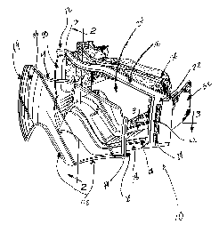
Figure 1 is a perspective view showing an eyewear made
in accordance with the present invention;
Figure 2 is an enlarged partial cross-sectional view of the
eyewear taken along the line 2-2 of Figure 1; and
Figure 3 is an enlarged partial cross-sectional view of the
eyewear, taken along line 3-3 of Figure 1.
DETAILED DESCRIPTION OF PREFERRED EMBODIMENTS
Referring to Figure 1, the eyewear of the invention is
shown and it is generally referred to as item 10. The eyewear comprises
a frame 12 and a translucent lens 14. For illustrative purposes, the lens
14 is shown detached from frame 12.
The frame 12 has a top side 16, a bottom side 18, a first
opposite side 20 and a second opposite side 22, all defining a lens
opening 24. A first groove 26 is located in the interior portion of the top
side 16 while a second groove 28 is located in the interior portion of the
bottom side 18.

CA 02290295 1999-11-23
Foam padding 30 may be provided to engage the wearer's
head and an elastic band 32 may also be provided for holding the
eyewear against the wearer's head.
In this embodiment of the invention, slots are situated in
5 each of the opposite sides 20 and 22. Slot 34 is shown on side 22 while
the slot on side 20 is not shown. These slots will effectively interact with
the lips at each side ends 36, 38 of lens 14. One lip 40 is shown in side
end 38 while the lip on side end 36 is not shown. Lens 14 also includes
portions 42 and 44 projecting rearwardly and located along the bottom
and top portions of lens 14, respectively. The rearward projecting lips 42
and 44 interact with the grooves 28 and 26, respectively, for insuring a
snug fit of lens 14 with frame 12.
Figure 2 shows in greater detail the interaction of
projection portion 42 with groove 28 as well as projection portion 44 with
groove 26. The lens 14 is therefore shown installed on frame 12.
Figure 3 gives a detailed view of opposite side 22. The
interaction of lip 40 and slot 34 is shown in greater detail. When installed,
lens 14 is retained in place on frame 12 by the interaction of, at one of the
ends (ie. 22), lip 40, post 46 and portion 48 of frame 12. Post 46 ensures
that lens 14 is retained on frame portion 48 all the while preventing lens
14 from moving sideways.
In order to remove the lens from frame 12, lens 14 is made
to flex by manual pressure applied thereon in a direction enabling
distance variation between the lips at each side end 36, 38. For manual

CA 02290295 1999-11-23
6
pressure exerted on lens 14 to enable a reduction in distance between
the lips at each of the lens side ends 36 and 38, lip 40 has to be moved
rearwardly (still by manual pressure) and displaced behind post 46. Once
lip 40 is passed post 46, lens 40 is free to be removed from frame 12.
The installation of lens 14 on frame 12 is achieved by
reversing the removal procedure. That is, one lens side end (eg. end 36)
is installed in one of the frame opposite sides (eg. end 20) by placing the
lip (not shown) on lens side end 36 in the slot (not shown) in opposite
side 20. The opposite lens side end 38 is then installed in the opposite
frame side 22 by displacing lip 40 behind post 46 until it snaps in place in
slot 34. Lens 14 is now locked in place on frame 12 and ready for use.
Although the present invention has been described herein
above with reference to preferred embodiments thereof, these
embodiments can be modified at will, within the scope of the appended
claims, without departing from the spirit and nature of the subject
invention.

Representative Drawing
A single figure which represents the drawing illustrating the invention.
Administrative Status

2024-08-01:As part of the Next Generation Patents (NGP) transition, the Canadian Patents Database (CPD) now contains a more detailed Event History, which replicates the Event Log of our new back-office solution.

Please note that "Inactive:" events refers to events no longer in use in our new back-office solution.

For a clearer understanding of the status of the application/patent presented on this page, the site Disclaimer , as well as the definitions for Patent , Event History , Maintenance Fee  and Payment History  should be consulted.

Event History

Description Date
Revocation of Agent Requirements Determined Compliant 2020-09-01
Application Not Reinstated by Deadline 2004-11-23
Time Limit for Reversal Expired 2004-11-23
Deemed Abandoned - Failure to Respond to Maintenance Fee Notice 2003-11-24
Letter Sent 2002-10-16
Reinstatement Requirements Deemed Compliant for All Abandonment Reasons 2002-10-04
Letter Sent 2002-08-21
Inactive: Office letter 2002-08-21
Revocation of Agent Requirements Determined Compliant 2002-08-15
Inactive: Office letter 2002-08-08
Revocation of Agent Request 2002-07-15
Revocation of Agent Request 2002-07-11
Deemed Abandoned - Failure to Respond to Maintenance Fee Notice 2001-11-23
Application Published (Open to Public Inspection) 2001-05-23
Inactive: Cover page published 2001-05-23
Letter Sent 2001-03-19
Inactive: Single transfer 2001-02-20
Inactive: First IPC assigned 2000-01-26
Inactive: Courtesy letter - Evidence 1999-12-29
Inactive: Filing certificate - No RFE (English) 1999-12-22
Application Received - Regular National 1999-12-16

Abandonment History

Abandonment Date Reason Reinstatement Date
2003-11-24
2001-11-23

Maintenance Fee

The last payment was received on 2002-10-04

Note : If the full payment has not been received on or before the date indicated, a further fee may be required which may be one of the following

  • the reinstatement fee;
  • the late payment fee; or
  • additional fee to reverse deemed expiry.

Patent fees are adjusted on the 1st of January every year. The amounts above are the current amounts if received by December 31 of the current year.
Please refer to the CIPO Patent Fees web page to see all current fee amounts.

Fee History

Fee Type Anniversary Year Due Date Paid Date
Application fee - standard 1999-11-23
Registration of a document 2001-02-20
Registration of a document 2002-07-11
Reinstatement 2002-10-04
MF (application, 3rd anniv.) - standard 03 2002-11-25 2002-10-04
MF (application, 2nd anniv.) - standard 02 2001-11-23 2002-10-04
Owners on Record

Note: Records showing the ownership history in alphabetical order.

Current Owners on Record
LEADER INDUSTRIES (2001) INC.
Past Owners on Record
RAYMOND CYR
Past Owners that do not appear in the "Owners on Record" listing will appear in other documentation within the application.
Documents

To view selected files, please enter reCAPTCHA code :


To view images, click a link in the Document Description column (Temporarily unavailable). To download the documents, select one or more checkboxes in the first column and then click the "Download Selected in PDF format (Zip Archive)" or the "Download Selected as Single PDF" button.

List of published and non-published patent-specific documents on the CPD .

If you have any difficulty accessing content, you can call the Client Service Centre at 1-866-997-1936 or send them an e-mail at CIPO Client Service Centre.

({010=All Documents, 020=As Filed, 030=As Open to Public Inspection, 040=At Issuance, 050=Examination, 060=Incoming Correspondence, 070=Miscellaneous, 080=Outgoing Correspondence, 090=Payment})


Document
Description 
Date
(yyyy-mm-dd) 
Number of pages   Size of Image (KB) 
Representative drawing 2001-05-22 1 18
Drawings 1999-11-22 2 90
Claims 1999-11-22 3 61
Abstract 1999-11-22 1 34
Description 1999-11-22 6 187
Filing Certificate (English) 1999-12-21 1 164
Request for evidence or missing transfer 2000-11-26 1 109
Courtesy - Certificate of registration (related document(s)) 2001-03-18 1 113
Reminder of maintenance fee due 2001-07-23 1 112
Courtesy - Abandonment Letter (Maintenance Fee) 2001-12-23 1 182
Notice of Reinstatement 2002-10-15 1 168
Courtesy - Abandonment Letter (Maintenance Fee) 2004-01-18 1 176
Reminder - Request for Examination 2004-07-25 1 117
Correspondence 1999-12-21 1 15
Correspondence 2002-08-07 1 11
Correspondence 2002-07-14 3 107
Correspondence 2002-07-10 3 96
Correspondence 2002-08-20 1 19
Correspondence 2002-08-07 1 24
Fees 2002-10-03 1 32