Language selection

Search

Patent 2290310 Summary

Third-party information liability

Some of the information on this Web page has been provided by external sources. The Government of Canada is not responsible for the accuracy, reliability or currency of the information supplied by external sources. Users wishing to rely upon this information should consult directly with the source of the information. Content provided by external sources is not subject to official languages, privacy and accessibility requirements.

Claims and Abstract availability

Any discrepancies in the text and image of the Claims and Abstract are due to differing posting times. Text of the Claims and Abstract are posted:

  • At the time the application is open to public inspection;
  • At the time of issue of the patent (grant).
(12) Patent: (11) CA 2290310
(54) English Title: ARRAY ANTENNA AND METHOD FOR OPERATING AN ARRAY ANTENNA
(54) French Title: ANTENNE RESEAU ET METHODE D'EXPLOITATION D'ANTENNE RESEAU
Status: Expired and beyond the Period of Reversal
Bibliographic Data
(51) International Patent Classification (IPC):
  • H01Q 21/20 (2006.01)
  • H01Q 03/26 (2006.01)
  • H01Q 21/06 (2006.01)
  • H01Q 21/29 (2006.01)
  • H01Q 25/00 (2006.01)
  • H01Q 25/02 (2006.01)
(72) Inventors :
  • REITS, BERNARD JOZEF
(73) Owners :
  • THALES NEDERLAND B.V.
(71) Applicants :
  • THALES NEDERLAND B.V.
(74) Agent: SMART & BIGGAR LP
(74) Associate agent:
(45) Issued: 2008-07-29
(22) Filed Date: 1999-11-24
(41) Open to Public Inspection: 2000-05-26
Examination requested: 2004-09-28
Availability of licence: N/A
Dedicated to the Public: N/A
(25) Language of filing: English

Patent Cooperation Treaty (PCT): No

(30) Application Priority Data:
Application No. Country/Territory Date
1010657 (Netherlands (Kingdom of the)) 1998-11-26

Abstracts

English Abstract

Array antenna of the monopulse type for realizing, on the basis of at least two groups of radiators, of at least two receiving beams for obtaining a difference signal. According to the invention, the at least two groups are homogeneously distributed within the antenna volume. In a transmit mode, the radiators are steered collectively, in a receive mode, the radiators are combined per group.


French Abstract

Une antenne réseau monopulsée servant à la réalisation, au moyen d'au moins deux groupes d'éléments rayonnants, d'au moins deux faisceaux de réception en vue de l'obtention d'un signal de différence. Selon l'invention, les deux groupes sont distribués de façon homogène à l'intérieur de l'antenne. En mode émission, les éléments rayonnants sont regroupés collectivement; en mode émissions, les éléments rayonnants sont combinés par groupe.

Claims

Note: Claims are shown in the official language in which they were submitted.

THE EMBODIMENTS OF THE INVENTION IN WHICH AN EXCLUSIVE
PROPERTY OR PRIVILEGE IS CLAIMED ARE DEFINED AS FOLLOWS:
1. Array antenna, comprising a set of radiators for the
transmission and reception of microwave radiation, which
radiators are distributed at least substantially
homogeneously within the volume of an imaginary three-
dimensional body, preferably spherical in shape, where each
individual radiator is via an adjustable phase shifter
connected to a transmitting network to choose a direction
in which microwave radiation can be transmitted,
characterized in that to enable reception, the set of
radiators is divided into two, three or four subsets, that
for each subset the radiators are distributed at least
substantially homogeneously within the body and that there
are provided two, three or four receiving networks
connected to the subsets for simultaneously choosing two,
three or four directions from which microwave radiation can
be received.
2. Method for operating an array antenna, comprising a
set of radiators for the transmission or reception of
microwave radiation, which radiators are distributed at
least substantially homogeneously within the volume of an
imaginary three-dimensional body, preferably spherical in
shape, whereby in a transmit mode, a transmitter signal is
applied, via adjustable phase shifters and a transmitting
network, to at least substantially all radiators for
generating a microwave beam in a predetermined direction,
characterized in that in a receive mode, two, three or four
subsets of at least substantially equal numbers of
radiators are combined via adjustable phase shifters and
two, three or four receiving networks for choosing two,
three or four directions from which microwave radiation can
be received.

6
3. Method as claimed in claim 2, characterized in that in
the transmit mode, the microwave beam is directed at a
target and that in the receive mode, the two, three or four
directions are chosen such that the output signals of the
two, three or four receiving networks can be combined to
yield a sum signal and at least one difference signal.

Description

Note: Descriptions are shown in the official language in which they were submitted.


CA 02290310 1999-11-24
1
Array antenna and method for operating an array antenna
The invention relates to an array antenna, comprising a set
of radiators for the transmission or reception of microwave
radiation, which radiators are distributed at least
substantially homogeneously within the volume of an
imaginary three-dimensional body, preferably spherical in
shape, where each individual radiator is via an adjustable
phase shifter connected to a transmitting network to choose
a direction in which microwave radiation can be
transmitted.
An array antenna of this type is known from DE-A 28.22.845.
For fire-control applications, however, this known array
antenna is unsuitable for determining the position of a
target with sufficient accuracy. For an accurate
determination, it is required to generate for a target the
error voltages known in the art, for instance in azimuth
and elevation, for instance under the application of a
monopulse antenna.
An array antenna of the monopulse type is known from patent
specification EP-B 0.207.511. The spherical antenna
disclosed in this specification is divided into eight
octants by means of which the error voltages are determined
by combining the output signals of the eight octants. The
known array antenna is most satisfactory if a target is
situated on an intersecting line of two dividing planes
between the octants, because this would imply symmetry
between the various antenna parts. For targets that do not
fulfil this condition, the array antenna performance is
suboptimal.
The array antenna according to the invention obviates this
drawback and is characterized in that to enable reception,
the set of radiators is divided into two, three or four

CA 02290310 2008-05-08
'24005-224
2
subsets, that for each subset the radiators are distributed
at least substantially homogeneously within the body and
that there are provided two, three or four receiving
networks connected to the subsets for simultaneously
choosing two, three or four directions from which microwave
radiation can be received.
The invention additionally relates to a method for
operating an array antenna, comprising a set of radiators
for the transmission or reception of microwave radiation,
which radiators are distributed at least substantially
homogeneously within the volume of an imaginary three-
dimensional body, preferably spherical in shape, whereby in
a transmit mode, a transmitter signal is applied, via
adjustable phase shifters and a transmitting network, to at
least substantially all radiators for generating a microwave
beam in a predetermined direction.
The inventive method is characterized in that in a
receive mode, two, three or four subsets of at least
substantially equal numbers of radiators are combined via
adjustable phase shifters and two, three or four receiving
networks for choosing two, three or four directions from
which microwave radiation can be received.
A favourable realization of the method is
characterized in that in the transmit mode, the microwave
beam is directed at a target and that in the receive mode,
the two, three or four directions are chosen such that the
output signals of the two, three or four receiving networks
can be combined to yield a sum signal and at least one
difference signal.
According to one aspect of the present invention,
there is provided an array antenna, comprising a set of

CA 02290310 2008-05-08
24005-224
2a
radiators for the transmission and reception of microwave
radiation, which radiators are distributed at least
substantially homogeneously within the volume of an
imaginary three-dimensional body, preferably spherical in
shape, where each individual radiator is via an adjustable
phase shifter connected to a transmitting network to choose
a direction in which microwave radiation can be transmitted,
characterized in that to enable reception, the set of
radiators is divided into two, three or four subsets, that
for each subset the radiators are distributed at least
substantially homogeneously within the body and that there
are provided two, three or four receiving networks connected
to the subsets for simultaneously choosing two, three or
four directions from which microwave radiation can be
received.
According to another aspect of the present
invention, there is provided a method for operating an array
antenna, comprising a set of radiators for the transmission
or reception of microwave radiation, which radiators are
distributed at least substantially homogeneously within the
volume of an imaginary three-dimensional body, preferably
spherical in shape, whereby in a transmit mode, a
transmitter signal is applied, via adjustable phase shifters
and a transmitting network, to at least substantially all
radiators for generating a microwave beam in a predetermined
direction, characterized in that in a receive mode, two,
three or four subsets of at least substantially equal
numbers of radiators are combined via adjustable phase
shifters and two, three or four receiving networks for
choosing two, three or four directions from which microwave
radiation can be received.
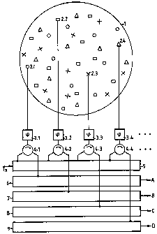
The invention will now be explained in further
detail with reference to the figure, which schematically

CA 02290310 2008-05-08
24005-224
2b
represents how a set of radiators 2,i is homogeneously
distributed within a sphere 1, at least such that, after
steering the

CA 02290310 1999-11-24
3
radiators in phase in a known manner, a beam with a
favourable main lobe/side lobe ratio is obtained. According
to the invention, the set of radiators is divided into four
subsets, each of which is likewise homogeneously
distributed within sphere 1. By way of illustration, the
radiators of the different subsets are marked with
circlets, squares, crosses and triangles. Via a
bidirectional phase shifter 3,i and a circulator 4,i, each
radiator 2,i is connected to a transmitting network 5 which
distributes microwave energy supplied by a transmitter (not
shown) over all radiators 2,i. The radiators 2,i of the
four different subsets are via the corresponding
circulators 4,i connected to four receiving networks
6,7,8,9, such that received microwave radiation can be
transmitted combined as four signals A,B,C,D.
In a first operational mode, the phase shifters 3,i are in
a known manner adjusted such that microwave energy supplied
via transmitting network 5 is unidirectionally transmitted
as a beam. Via phase shifters 3,i, received echo signals
are coherently combined in a known manner to yield four
mutually coherent echo signals at the outputs A,B,C,D which
can subsequently be summed in order to obtain one echo
signal.
In a second operational mode, the phase shifters 3,i can in
a known manner be adjusted such that microwave energy
supplied via transmitting network 5 is unidirectionally
transmitted as a beam. After transmission, the phase
shifters 3.i are readjusted such that the four subsets
generate four different receiving beams, each of which
makes a small angle with the transmitted beam. It would
then make sense to position the beams such that a
conventional monopulse measurement is performed so that the
received echo signals can via the phase shifters 3.i be
coherently combined to yield four monopulse output signals

CA 02290310 1999-11-24
4
A,B,C,D which can subsequently be converted into sum and
difference signals.
Another possibility is to realize the invention with merely
two subsets of radiators 2,i, in which case an error
voltage in azimuth or in elevation can fully analogously be
determined from the signals A and B in a radar
transmission. The even radar transmissions can then for
instance be used to determine an error voltage in azimuth,
the odd transmissions serving to determine an error voltage
in elevation.
Yet another possibility is to realize the invention with
three subsets of radiators 2,i; in this case three
receiving beams are realized, one of which is for instance
positioned above the transmission beam and two below the
transmission beam, one to the left and one to the right,
after which the error voltages in azimuth and elevation can
in an obvious manner be determined from the signals A, B
and C.

Representative Drawing
A single figure which represents the drawing illustrating the invention.
Administrative Status

2024-08-01:As part of the Next Generation Patents (NGP) transition, the Canadian Patents Database (CPD) now contains a more detailed Event History, which replicates the Event Log of our new back-office solution.

Please note that "Inactive:" events refers to events no longer in use in our new back-office solution.

For a clearer understanding of the status of the application/patent presented on this page, the site Disclaimer , as well as the definitions for Patent , Event History , Maintenance Fee  and Payment History  should be consulted.

Event History

Description Date
Time Limit for Reversal Expired 2016-11-24
Letter Sent 2015-11-24
Grant by Issuance 2008-07-29
Inactive: Cover page published 2008-07-28
Letter Sent 2008-05-23
Amendment After Allowance Requirements Determined Compliant 2008-05-23
Inactive: Amendment after Allowance Fee Processed 2008-05-08
Inactive: Final fee received 2008-05-08
Amendment After Allowance (AAA) Received 2008-05-08
Pre-grant 2008-05-08
Notice of Allowance is Issued 2007-11-13
Letter Sent 2007-11-13
Notice of Allowance is Issued 2007-11-13
Inactive: Approved for allowance (AFA) 2007-10-22
Inactive: IPC from MCD 2006-03-12
Amendment Received - Voluntary Amendment 2004-11-30
Letter Sent 2004-10-08
Request for Examination Requirements Determined Compliant 2004-09-28
All Requirements for Examination Determined Compliant 2004-09-28
Request for Examination Received 2004-09-28
Letter Sent 2001-08-03
Application Published (Open to Public Inspection) 2000-05-26
Inactive: Cover page published 2000-05-25
Inactive: First IPC assigned 2000-02-11
Inactive: IPC assigned 2000-02-11
Letter Sent 1999-12-21
Inactive: Filing certificate - No RFE (English) 1999-12-17
Application Received - Regular National 1999-12-16

Abandonment History

There is no abandonment history.

Maintenance Fee

The last payment was received on 2007-11-08

Note : If the full payment has not been received on or before the date indicated, a further fee may be required which may be one of the following

  • the reinstatement fee;
  • the late payment fee; or
  • additional fee to reverse deemed expiry.

Patent fees are adjusted on the 1st of January every year. The amounts above are the current amounts if received by December 31 of the current year.
Please refer to the CIPO Patent Fees web page to see all current fee amounts.

Owners on Record

Note: Records showing the ownership history in alphabetical order.

Current Owners on Record
THALES NEDERLAND B.V.
Past Owners on Record
BERNARD JOZEF REITS
Past Owners that do not appear in the "Owners on Record" listing will appear in other documentation within the application.
Documents

To view selected files, please enter reCAPTCHA code :


To view images, click a link in the Document Description column (Temporarily unavailable). To download the documents, select one or more checkboxes in the first column and then click the "Download Selected in PDF format (Zip Archive)" or the "Download Selected as Single PDF" button.

List of published and non-published patent-specific documents on the CPD .

If you have any difficulty accessing content, you can call the Client Service Centre at 1-866-997-1936 or send them an e-mail at CIPO Client Service Centre.

({010=All Documents, 020=As Filed, 030=As Open to Public Inspection, 040=At Issuance, 050=Examination, 060=Incoming Correspondence, 070=Miscellaneous, 080=Outgoing Correspondence, 090=Payment})


Document
Description 
Date
(yyyy-mm-dd) 
Number of pages   Size of Image (KB) 
Representative drawing 2000-05-22 1 5
Description 1999-11-23 4 173
Abstract 1999-11-23 1 13
Claims 1999-11-23 2 61
Drawings 1999-11-23 1 16
Description 2008-05-07 6 218
Representative drawing 2008-07-09 1 7
Courtesy - Certificate of registration (related document(s)) 1999-12-20 1 115
Filing Certificate (English) 1999-12-16 1 164
Reminder of maintenance fee due 2001-07-24 1 112
Reminder - Request for Examination 2004-07-26 1 117
Acknowledgement of Request for Examination 2004-10-07 1 185
Commissioner's Notice - Application Found Allowable 2007-11-12 1 164
Maintenance Fee Notice 2016-01-04 1 171
Correspondence 2008-05-07 2 55