Sélection de la langue

Search

Sommaire du brevet 2290310 

Énoncé de désistement de responsabilité concernant l'information provenant de tiers

Une partie des informations de ce site Web a été fournie par des sources externes. Le gouvernement du Canada n'assume aucune responsabilité concernant la précision, l'actualité ou la fiabilité des informations fournies par les sources externes. Les utilisateurs qui désirent employer cette information devraient consulter directement la source des informations. Le contenu fourni par les sources externes n'est pas assujetti aux exigences sur les langues officielles, la protection des renseignements personnels et l'accessibilité.

Disponibilité de l'Abrégé et des Revendications

L'apparition de différences dans le texte et l'image des Revendications et de l'Abrégé dépend du moment auquel le document est publié. Les textes des Revendications et de l'Abrégé sont affichés :

  • lorsque la demande peut être examinée par le public;
  • lorsque le brevet est émis (délivrance).
(12) Brevet: (11) CA 2290310
(54) Titre français: ANTENNE RESEAU ET METHODE D'EXPLOITATION D'ANTENNE RESEAU
(54) Titre anglais: ARRAY ANTENNA AND METHOD FOR OPERATING AN ARRAY ANTENNA
Statut: Périmé et au-delà du délai pour l’annulation
Données bibliographiques
(51) Classification internationale des brevets (CIB):
  • H01Q 21/20 (2006.01)
  • H01Q 03/26 (2006.01)
  • H01Q 21/06 (2006.01)
  • H01Q 21/29 (2006.01)
  • H01Q 25/00 (2006.01)
  • H01Q 25/02 (2006.01)
(72) Inventeurs :
  • REITS, BERNARD JOZEF
(73) Titulaires :
  • THALES NEDERLAND B.V.
(71) Demandeurs :
  • THALES NEDERLAND B.V.
(74) Agent: SMART & BIGGAR LP
(74) Co-agent:
(45) Délivré: 2008-07-29
(22) Date de dépôt: 1999-11-24
(41) Mise à la disponibilité du public: 2000-05-26
Requête d'examen: 2004-09-28
Licence disponible: S.O.
Cédé au domaine public: S.O.
(25) Langue des documents déposés: Anglais

Traité de coopération en matière de brevets (PCT): Non

(30) Données de priorité de la demande:
Numéro de la demande Pays / territoire Date
1010657 (Pays-Bas (Royaume des)) 1998-11-26

Abrégés

Abrégé français

Une antenne réseau monopulsée servant à la réalisation, au moyen d'au moins deux groupes d'éléments rayonnants, d'au moins deux faisceaux de réception en vue de l'obtention d'un signal de différence. Selon l'invention, les deux groupes sont distribués de façon homogène à l'intérieur de l'antenne. En mode émission, les éléments rayonnants sont regroupés collectivement; en mode émissions, les éléments rayonnants sont combinés par groupe.


Abrégé anglais

Array antenna of the monopulse type for realizing, on the basis of at least two groups of radiators, of at least two receiving beams for obtaining a difference signal. According to the invention, the at least two groups are homogeneously distributed within the antenna volume. In a transmit mode, the radiators are steered collectively, in a receive mode, the radiators are combined per group.

Revendications

Note : Les revendications sont présentées dans la langue officielle dans laquelle elles ont été soumises.


THE EMBODIMENTS OF THE INVENTION IN WHICH AN EXCLUSIVE
PROPERTY OR PRIVILEGE IS CLAIMED ARE DEFINED AS FOLLOWS:
1. Array antenna, comprising a set of radiators for the
transmission and reception of microwave radiation, which
radiators are distributed at least substantially
homogeneously within the volume of an imaginary three-
dimensional body, preferably spherical in shape, where each
individual radiator is via an adjustable phase shifter
connected to a transmitting network to choose a direction
in which microwave radiation can be transmitted,
characterized in that to enable reception, the set of
radiators is divided into two, three or four subsets, that
for each subset the radiators are distributed at least
substantially homogeneously within the body and that there
are provided two, three or four receiving networks
connected to the subsets for simultaneously choosing two,
three or four directions from which microwave radiation can
be received.
2. Method for operating an array antenna, comprising a
set of radiators for the transmission or reception of
microwave radiation, which radiators are distributed at
least substantially homogeneously within the volume of an
imaginary three-dimensional body, preferably spherical in
shape, whereby in a transmit mode, a transmitter signal is
applied, via adjustable phase shifters and a transmitting
network, to at least substantially all radiators for
generating a microwave beam in a predetermined direction,
characterized in that in a receive mode, two, three or four
subsets of at least substantially equal numbers of
radiators are combined via adjustable phase shifters and
two, three or four receiving networks for choosing two,
three or four directions from which microwave radiation can
be received.

6
3. Method as claimed in claim 2, characterized in that in
the transmit mode, the microwave beam is directed at a
target and that in the receive mode, the two, three or four
directions are chosen such that the output signals of the
two, three or four receiving networks can be combined to
yield a sum signal and at least one difference signal.

Description

Note : Les descriptions sont présentées dans la langue officielle dans laquelle elles ont été soumises.

CA 02290310 1999-11-24
1
Array antenna and method for operating an array antenna
The invention relates to an array antenna, comprising a set
of radiators for the transmission or reception of microwave
radiation, which radiators are distributed at least
substantially homogeneously within the volume of an
imaginary three-dimensional body, preferably spherical in
shape, where each individual radiator is via an adjustable
phase shifter connected to a transmitting network to choose
a direction in which microwave radiation can be
transmitted.
An array antenna of this type is known from DE-A 28.22.845.
For fire-control applications, however, this known array
antenna is unsuitable for determining the position of a
target with sufficient accuracy. For an accurate
determination, it is required to generate for a target the
error voltages known in the art, for instance in azimuth
and elevation, for instance under the application of a
monopulse antenna.
An array antenna of the monopulse type is known from patent
specification EP-B 0.207.511. The spherical antenna
disclosed in this specification is divided into eight
octants by means of which the error voltages are determined
by combining the output signals of the eight octants. The
known array antenna is most satisfactory if a target is
situated on an intersecting line of two dividing planes
between the octants, because this would imply symmetry
between the various antenna parts. For targets that do not
fulfil this condition, the array antenna performance is
suboptimal.
The array antenna according to the invention obviates this
drawback and is characterized in that to enable reception,
the set of radiators is divided into two, three or four

CA 02290310 2008-05-08
'24005-224
2
subsets, that for each subset the radiators are distributed
at least substantially homogeneously within the body and
that there are provided two, three or four receiving
networks connected to the subsets for simultaneously
choosing two, three or four directions from which microwave
radiation can be received.
The invention additionally relates to a method for
operating an array antenna, comprising a set of radiators
for the transmission or reception of microwave radiation,
which radiators are distributed at least substantially
homogeneously within the volume of an imaginary three-
dimensional body, preferably spherical in shape, whereby in
a transmit mode, a transmitter signal is applied, via
adjustable phase shifters and a transmitting network, to at
least substantially all radiators for generating a microwave
beam in a predetermined direction.
The inventive method is characterized in that in a
receive mode, two, three or four subsets of at least
substantially equal numbers of radiators are combined via
adjustable phase shifters and two, three or four receiving
networks for choosing two, three or four directions from
which microwave radiation can be received.
A favourable realization of the method is
characterized in that in the transmit mode, the microwave
beam is directed at a target and that in the receive mode,
the two, three or four directions are chosen such that the
output signals of the two, three or four receiving networks
can be combined to yield a sum signal and at least one
difference signal.
According to one aspect of the present invention,
there is provided an array antenna, comprising a set of

CA 02290310 2008-05-08
24005-224
2a
radiators for the transmission and reception of microwave
radiation, which radiators are distributed at least
substantially homogeneously within the volume of an
imaginary three-dimensional body, preferably spherical in
shape, where each individual radiator is via an adjustable
phase shifter connected to a transmitting network to choose
a direction in which microwave radiation can be transmitted,
characterized in that to enable reception, the set of
radiators is divided into two, three or four subsets, that
for each subset the radiators are distributed at least
substantially homogeneously within the body and that there
are provided two, three or four receiving networks connected
to the subsets for simultaneously choosing two, three or
four directions from which microwave radiation can be
received.
According to another aspect of the present
invention, there is provided a method for operating an array
antenna, comprising a set of radiators for the transmission
or reception of microwave radiation, which radiators are
distributed at least substantially homogeneously within the
volume of an imaginary three-dimensional body, preferably
spherical in shape, whereby in a transmit mode, a
transmitter signal is applied, via adjustable phase shifters
and a transmitting network, to at least substantially all
radiators for generating a microwave beam in a predetermined
direction, characterized in that in a receive mode, two,
three or four subsets of at least substantially equal
numbers of radiators are combined via adjustable phase
shifters and two, three or four receiving networks for
choosing two, three or four directions from which microwave
radiation can be received.
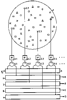
The invention will now be explained in further
detail with reference to the figure, which schematically

CA 02290310 2008-05-08
24005-224
2b
represents how a set of radiators 2,i is homogeneously
distributed within a sphere 1, at least such that, after
steering the

CA 02290310 1999-11-24
3
radiators in phase in a known manner, a beam with a
favourable main lobe/side lobe ratio is obtained. According
to the invention, the set of radiators is divided into four
subsets, each of which is likewise homogeneously
distributed within sphere 1. By way of illustration, the
radiators of the different subsets are marked with
circlets, squares, crosses and triangles. Via a
bidirectional phase shifter 3,i and a circulator 4,i, each
radiator 2,i is connected to a transmitting network 5 which
distributes microwave energy supplied by a transmitter (not
shown) over all radiators 2,i. The radiators 2,i of the
four different subsets are via the corresponding
circulators 4,i connected to four receiving networks
6,7,8,9, such that received microwave radiation can be
transmitted combined as four signals A,B,C,D.
In a first operational mode, the phase shifters 3,i are in
a known manner adjusted such that microwave energy supplied
via transmitting network 5 is unidirectionally transmitted
as a beam. Via phase shifters 3,i, received echo signals
are coherently combined in a known manner to yield four
mutually coherent echo signals at the outputs A,B,C,D which
can subsequently be summed in order to obtain one echo
signal.
In a second operational mode, the phase shifters 3,i can in
a known manner be adjusted such that microwave energy
supplied via transmitting network 5 is unidirectionally
transmitted as a beam. After transmission, the phase
shifters 3.i are readjusted such that the four subsets
generate four different receiving beams, each of which
makes a small angle with the transmitted beam. It would
then make sense to position the beams such that a
conventional monopulse measurement is performed so that the
received echo signals can via the phase shifters 3.i be
coherently combined to yield four monopulse output signals

CA 02290310 1999-11-24
4
A,B,C,D which can subsequently be converted into sum and
difference signals.
Another possibility is to realize the invention with merely
two subsets of radiators 2,i, in which case an error
voltage in azimuth or in elevation can fully analogously be
determined from the signals A and B in a radar
transmission. The even radar transmissions can then for
instance be used to determine an error voltage in azimuth,
the odd transmissions serving to determine an error voltage
in elevation.
Yet another possibility is to realize the invention with
three subsets of radiators 2,i; in this case three
receiving beams are realized, one of which is for instance
positioned above the transmission beam and two below the
transmission beam, one to the left and one to the right,
after which the error voltages in azimuth and elevation can
in an obvious manner be determined from the signals A, B
and C.

Dessin représentatif
Une figure unique qui représente un dessin illustrant l'invention.
États administratifs

2024-08-01 : Dans le cadre de la transition vers les Brevets de nouvelle génération (BNG), la base de données sur les brevets canadiens (BDBC) contient désormais un Historique d'événement plus détaillé, qui reproduit le Journal des événements de notre nouvelle solution interne.

Veuillez noter que les événements débutant par « Inactive : » se réfèrent à des événements qui ne sont plus utilisés dans notre nouvelle solution interne.

Pour une meilleure compréhension de l'état de la demande ou brevet qui figure sur cette page, la rubrique Mise en garde , et les descriptions de Brevet , Historique d'événement , Taxes périodiques et Historique des paiements devraient être consultées.

Historique d'événement

Description Date
Le délai pour l'annulation est expiré 2016-11-24
Lettre envoyée 2015-11-24
Accordé par délivrance 2008-07-29
Inactive : Page couverture publiée 2008-07-28
Lettre envoyée 2008-05-23
Exigences de modification après acceptation - jugée conforme 2008-05-23
Inactive : Taxe de modif. après accept. traitée 2008-05-08
Inactive : Taxe finale reçue 2008-05-08
Modification après acceptation reçue 2008-05-08
Préoctroi 2008-05-08
Un avis d'acceptation est envoyé 2007-11-13
Lettre envoyée 2007-11-13
Un avis d'acceptation est envoyé 2007-11-13
Inactive : Approuvée aux fins d'acceptation (AFA) 2007-10-22
Inactive : CIB de MCD 2006-03-12
Modification reçue - modification volontaire 2004-11-30
Lettre envoyée 2004-10-08
Exigences pour une requête d'examen - jugée conforme 2004-09-28
Toutes les exigences pour l'examen - jugée conforme 2004-09-28
Requête d'examen reçue 2004-09-28
Lettre envoyée 2001-08-03
Demande publiée (accessible au public) 2000-05-26
Inactive : Page couverture publiée 2000-05-25
Inactive : CIB en 1re position 2000-02-11
Inactive : CIB attribuée 2000-02-11
Lettre envoyée 1999-12-21
Inactive : Certificat de dépôt - Sans RE (Anglais) 1999-12-17
Demande reçue - nationale ordinaire 1999-12-16

Historique d'abandonnement

Il n'y a pas d'historique d'abandonnement

Taxes périodiques

Le dernier paiement a été reçu le 2007-11-08

Avis : Si le paiement en totalité n'a pas été reçu au plus tard à la date indiquée, une taxe supplémentaire peut être imposée, soit une des taxes suivantes :

  • taxe de rétablissement ;
  • taxe pour paiement en souffrance ; ou
  • taxe additionnelle pour le renversement d'une péremption réputée.

Les taxes sur les brevets sont ajustées au 1er janvier de chaque année. Les montants ci-dessus sont les montants actuels s'ils sont reçus au plus tard le 31 décembre de l'année en cours.
Veuillez vous référer à la page web des taxes sur les brevets de l'OPIC pour voir tous les montants actuels des taxes.

Historique des taxes

Type de taxes Anniversaire Échéance Date payée
Enregistrement d'un document 1999-11-24
Taxe pour le dépôt - générale 1999-11-24
TM (demande, 2e anniv.) - générale 02 2001-11-26 2001-10-23
TM (demande, 3e anniv.) - générale 03 2002-11-25 2002-11-06
TM (demande, 4e anniv.) - générale 04 2003-11-24 2003-11-07
Requête d'examen - générale 2004-09-28
TM (demande, 5e anniv.) - générale 05 2004-11-24 2004-11-04
TM (demande, 6e anniv.) - générale 06 2005-11-24 2005-11-07
TM (demande, 7e anniv.) - générale 07 2006-11-24 2006-11-07
TM (demande, 8e anniv.) - générale 08 2007-11-26 2007-11-08
Taxe finale - générale 2008-05-08
2008-05-08
TM (brevet, 9e anniv.) - générale 2008-11-24 2008-10-29
TM (brevet, 10e anniv.) - générale 2009-11-24 2009-10-26
TM (brevet, 11e anniv.) - générale 2010-11-24 2010-10-28
TM (brevet, 12e anniv.) - générale 2011-11-24 2011-10-20
TM (brevet, 13e anniv.) - générale 2012-11-26 2012-10-16
TM (brevet, 14e anniv.) - générale 2013-11-25 2013-10-22
TM (brevet, 15e anniv.) - générale 2014-11-24 2014-10-29
Titulaires au dossier

Les titulaires actuels et antérieures au dossier sont affichés en ordre alphabétique.

Titulaires actuels au dossier
THALES NEDERLAND B.V.
Titulaires antérieures au dossier
BERNARD JOZEF REITS
Les propriétaires antérieurs qui ne figurent pas dans la liste des « Propriétaires au dossier » apparaîtront dans d'autres documents au dossier.
Documents

Pour visionner les fichiers sélectionnés, entrer le code reCAPTCHA :


Pour visualiser une image, cliquer sur un lien dans la colonne description du document (Temporairement non-disponible). Pour télécharger l'image (les images), cliquer l'une ou plusieurs cases à cocher dans la première colonne et ensuite cliquer sur le bouton "Télécharger sélection en format PDF (archive Zip)" ou le bouton "Télécharger sélection (en un fichier PDF fusionné)".

Liste des documents de brevet publiés et non publiés sur la BDBC .

Si vous avez des difficultés à accéder au contenu, veuillez communiquer avec le Centre de services à la clientèle au 1-866-997-1936, ou envoyer un courriel au Centre de service à la clientèle de l'OPIC.

({010=Tous les documents, 020=Au moment du dépôt, 030=Au moment de la mise à la disponibilité du public, 040=À la délivrance, 050=Examen, 060=Correspondance reçue, 070=Divers, 080=Correspondance envoyée, 090=Paiement})


Description du
Document 
Date
(aaaa-mm-jj) 
Nombre de pages   Taille de l'image (Ko) 
Dessin représentatif 2000-05-22 1 5
Description 1999-11-23 4 173
Abrégé 1999-11-23 1 13
Revendications 1999-11-23 2 61
Dessins 1999-11-23 1 16
Description 2008-05-07 6 218
Dessin représentatif 2008-07-09 1 7
Courtoisie - Certificat d'enregistrement (document(s) connexe(s)) 1999-12-20 1 115
Certificat de dépôt (anglais) 1999-12-16 1 164
Rappel de taxe de maintien due 2001-07-24 1 112
Rappel - requête d'examen 2004-07-26 1 117
Accusé de réception de la requête d'examen 2004-10-07 1 185
Avis du commissaire - Demande jugée acceptable 2007-11-12 1 164
Avis concernant la taxe de maintien 2016-01-04 1 171
Correspondance 2008-05-07 2 55