Note: Descriptions are shown in the official language in which they were submitted.
CA 02290633 1999-11-12
WO 98/55852 PCT/US98/11667
1
MICROFABRICATED STRUCTURES FOR FACILITATING FLUID
s INTRODUCTION INTO MICROFLUIDIC DEVICES
BACKGROUND OF THE INVENTION
The present invention relates generally to
microfluidic systems and devices and methods for their use.
More particularly, the present invention provides structures
and methods which facilitate the introduction of fluids into
devices hav_ng microfluidic channels.
Considerable wor'. is now underway to develop
"microfluidic" systems, particularly for performing chemical,
clinical, and environmental analysis of chemical and
biological specimens. The term microfluidic refers to a
system or device having a network of chambers connected by
channels, in which the channels have mesoscale dimensions,
e.g., having at least one cross-sectional dimension in the
range from about 0.1 ~m to about 500um. Microfluidic
substrates are often fabricated using photolithography, wet
chemical etching, and other techniques similar to those
employed in the semiconductor industry. The resulting devices
can be used to perform a variety of sophisticated chemical and
biological analytical techniques.
Microfluidic analytical systems have a number of
advantages over conventional chemical or physical laboratory
techniques. For example, microfluidic systems are
particularly well adapted for analyzing small sample sizes,
typically making use of samples on the order of nanoliters and
even picoliters. The substrates may be produced at relatively
low cost, and the channels can be arranged to perform numerous
specific analytical operations, including mixing, dispensing,
valuing, reactions, detections, electrophoresis, and the like.
The analytical capabilities of microfluidic systems are
generally enhanced by increasing the number and complexity of
network channels, reaction chambers, and the like.
CA 02290633 1999-11-12
WO 98/55852 PCT/US98/11667
2
Substantial advances have recently been made in the
general areas of flow control and physical interactions
between the samples and the supporting analytical structures.
Flow control management may make use of a variety of
mechanisms, including the patterned application of voltage,
current, or electrical power to the substrate (for example, to
induce and/or control electrokinetic flow or electrophoretic
separations). Alternatively, fluid flows may be induced
mechanically through the application of differential pressure,
acoustic energy, or the like. Selective heating, cooling,
exposure to light or other radiation, or other inputs may be
provided at selected locations distributed about the substrate
to promote the desired chemical and/or biological
interactions. Similarly, measurements of light or other
emissions, electrical/electrochemical signals, and pH may be
taken from the substrate to provide analytical results. As
work has progressed in each of these areas, the channel size
has gradually decreased while the channel network has
increased in complexity, significantly enhancing the overall
capabilities of microfluidic systems.
Unfortunately, work in connection with the present
invention has found that the structures and methods used to
introduce samples and other fluids into microfluidic
substrates can limit the capabilities of known microfluidic
systems. Fluid introduction ports provide an interface
between the surrounding world and the microfluidic channel
network. The total number of samples and other fluids which
can be processed on a microfluidic substrate is now limited by
the size and/or the number of ports through which these fluids
are introduced to the microfluidic system. Known structures
and methods for introduction of fluids into microfluidic
systems also generally result in the transfer of a much
greater volume of fluid than is needed for microfluidic
analysis.
Work in connection with the present invention has
also identified unexpected failure modes associated with known
methods for introducing fluids to microfluidic channels.
These failure modes may result in less than desirable overall
CA 02290633 1999-11-12
WO 98/55852 PCT/US98111667
3
reliability for microfluidic systems. Finally, a need has
been identified for some mechanism to accurately pre-position
different fluids within a contiguous microfluidic network, so
as to facilitate a variety of microfluidic analyses.
It would therefore be desirable to provide improved
structures, systems, and methods which overcome or
substantially mitigate at least some of the problems set forth
above. In particular, it would be desirable to provide
microfluidic systems which facilitated the transfer of small
volumes of fluids to an introduction port of a microfluidic
substrate, and to increase the number of fluids which can be
manipulated within the substrate without increasing the
overall size of the substrate itself. It would be
particularly desirable to provide microfluidic introduction
ports which could accept multiple fluid samples, and which
were less prone to failure than known introduction port
structures. Finally, it would be advantageous to provide
microfluidic channel networks which are adapted to
controllably pre-position differing liquids within adjoining
channels for analysis of samples using differing fluid media.
SUNIHIARY OF THE INVENTION
The present invention overcomes at least some of the
deficiencies of known structures and methods for introducing
fluids into microfluidic substrates. In some embodiments,
fluid introduction can be facilitated through the use of a
port which extends entirely through the substrate structure.
Capillary forces can be used to retain the fluid within such a
through-hole port, rather than relying on gravity to hold the
fluid within a cup-like blind hole. A series of samples or
other fluids may be introduced through a single through-hole
port by sequentially blowing the fluid out of the port, and
replacing the removed fluid with different fluid.
Advantageously, an array of such through-hole ports can wick
fluids from the surfaces of a corresponding array of pins,
thereby avoiding the need for complex pipette systems. In
another aspect, the present invention provides microfluidic
CA 02290633 1999-11-12
WO 98/55852 PCT/US98/11667
4
substrates having channels which vary in cross-sectional
dimension so that capillary action spreads a fluid only within
a limited portion of the channel network. In yet another
aspect, the introduction ports of the present invention may
include a multiplicity of very small channels leading from the
port to a larger microfluidic fluid channel. These small
channels filter out particles or other contaminants which
might otherwise block the microfluidic channel.
In a first aspect, the present invention provides a
microfluidic system comprising a substrate having an upper
surface, a lower surface, and a microfluidic channel disposed
between these surfaces. A wall of the substrate borders a
port for receiving fluid. The port is in fluid communication
with the channel, and the port is open at both the upper
surface of the substrate, and at the lower surface of the
substrate.
Generally, the port has a cross-sectional dimension
which is sufficiently small so that capillary forces restrain
the fluid within the port. The specific size of the port will
depend in part on the properties of the material along its
border. The capillary forces between the port and the fluid
can also be used to transfer the fluid from the outer surface
of a pin, rather than relying on a complex pipette system.
The use of a through-hole port also facilitates the removal of
the fluid from the port, as the fluid can be blown through the
substrate with differential pressure, or simply displaced from
the port with an alternate fluid. Optionally, the lower
surface of the substrate may have a hydrophobic material to
prevent the sample from spreading along the lower surface,
while a hydrophilic rod or capillary tube may facilitate
decanting of the fluid from the port.
In another aspect, the present invention provides a
method for introducing a fluid into a microfluidic channel of
a substrate. The method comprises transporting the fluid from
outside the substrate to a port of the substrate through a
first surface. The port extends through the substrate, and
opens on a second surface of the substrate. The microfluidic
channel of the substrate is in fluid communication with the
CA 02290633 1999-11-12
WO 98/55852 PCT/US98I11667
port between the first and second surfaces. The fluid is
restrained within the port at least in part by a capillary
force between the port and the fluid.
In yet another aspect, the present invention
5 provides a method for introducing a plurality of samples into
a microfluidic substrate. The method comprises forming a
volume of each sample on an associated pin. The pins are
arranged in an array, and the array of pins is aligned with an
array of ports on the substrate. The aligned pins and ports
are brought together so that the volumes transfer from the
pins to associated ports of the substrate.
In yet another aspect, the present invention
provides a method for introducing a plurality of fluids into a
microfluidic substrate. The method comprises inserting a
first fluid into a port of the substrate. A portion of the
first fluid is transferred from the port into a microfluidic
channel of the substrate. An unused portion of the first
fluid is removed from the port, and a second fluid is inserted
into the port.
The present invention also provides a microfluidic
system comprising a body having a first channel and a
capillary limit region. A second channel is in fluid
communication with the first channel through the limit region.
The second channel has a cross-sectional dimension adjacent
the limit region which is larger than a cross-sectional
dimension of the limit region. This difference in cross-
sectional dimensions inhibits wicking from the limit region
into the second channel.
Generally, a minimum cross-sectional dimension of
the limit region is sufficiently smaller than a minimum cross-
sectional dimension of the second channel so that differential
capillary forces prevent wicking of fluid from the first
channel, through the limit region, and into the second channel
when there is no fluid in the second channel. Typically, the
first channel and limit region end at the intersection with
the second channel, while the second channel continues on past
the intersection (like the top bar in a "T"). This structure
is particularly advantageous to establish predetermined
CA 02290633 1999-11-12
WO 98/55852 PCT/US98/11667
6
boundaries between two different fluids within a microfluidic
channel network, as a fluid which is introduced into the first
channel will wick through the channel to the limit region, but
will not wick beyond the limit region into the second channel.
A second different fluid can then wick through the second
channel, beyond the intersection with the first limit region,
thereby defining a boundary between the first and second
fluids at the channel intersection.
In another aspect, the present invention provides a
method for controllably distributing fluids within
microfluidic substrates. The method comprises wicking a first
fluid along a first channel and into a capillary limit region.
The first fluid is prevented from wicking beyond the limit
region and into a second channel by differential capillary
force .
The present invention also provides a filtered
microfluidic system comprising a substrate having a reservoir
and a channel having a fluid microfluidic cross-section. A
plurality of filter channels extend in parallel between the
reservoir and the channel. Each filter channel has a cross-
sectional dimension which is smaller than a fluid channel
cross-sectional dimension of the microfluidic channel.
In yet another aspect, the present invention
provides a method for filtering a fluid sample entering a
microfluidic channel network. The method comprises
introducing the fluid sample into a port, and passing the
fluid sample through a plurality of filter channels which are
arranged in parallel. The filter channels block particles
having cross-sections which are larger than a maximum filter
particle size. The filtered fluid sample is collected and
transported through a microfluidic channel having a cross-
section which is larger than the maximum filter size.
BRIEF DESCRIPTION OF THE DRAWINGS
Fig. 1 is a cross-sectional view of a typical
microfluidic fluid introduction system, in which a pipette
deposits fluid in a blind hole, and in which the fluid must
CA 02290633 1999-11-12
WO 98/55852 PCT/US98/11667
7
pass through a single microfluidic channel to enter the
channel network.
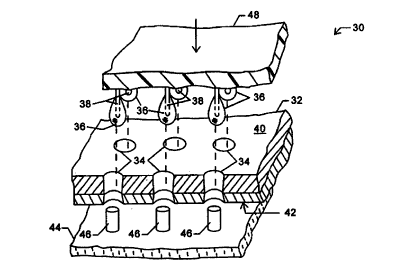
Fig. 2 is a perspective view in partial cross-
section showing a system for introducing an array of fluid
samples to a corresponding array of through-hole ports, and
also shows the use of hydrophilic rods to facilitate decanting
the fluid samples from the through-hole ports, according to
the principles of the present invention.
Fig. 3 is a cross-sectional view illustrating the
use of capillary forces to retain a fluid sample within a
through-hole port, and also illustrates the use of
electrokinetic forces to transport the fluid within the
microfluidic substrate.
Fig. 4 is a cross-sectional view showing the use of
differential pressure and a hydrophilic rod to decant a sample
from a through-hole port.
Fig. 5 is a plan view of an integrated reservoir and
filter to prevent particles from blocking the microfluidic
channels of the substrate.
Fig. 6 is a cross-sectional view showing the
integrated port and filter of Fig. 5.
Fig. 7 schematically illustrates a microfluidic
substrate having fluid stops which allow two different fluids
to be positioned within the network, with the boundaries
between the fluids being located at predetermined limit
regions.
Figs. 8 and 9 are cross-sectional views showing the
structure and operation of the fluid stop limit regions of
Fig. 7.
DETAILED DESCRIPTION OF THE SPECIFIC EMBODIMENTS
A typical microfluidic introduction system and
method is schematically illustrated in Fig. 1. A substrate 10
generally comprises an upper portion 12 through which a port
14 has been drilled. A lower portion 16 is bonded to upper
portion 12, the lower portion having a microfluidic channel 18
which is in fluid communication with port 14. A pipette 20
CA 02290633 1999-11-12
WO 98/55852 PCT/US98/11667
8
delivers fluid 22 to port 14, typically relying on pneumatic
and/or hydraulic pressure to deposit the fluid in the port.
Work in connection with the present invention has
identified failure modes which could prevent fluid 22 from
reaching channel 18, thereby interfering with the intended
operation of microfluidic substrate 10. In the first failure
mode, any particles in the fluid, in the pipette, or in the
port may flow with the fluid from the port toward channel 18.
Particles which are not large enough to enter microfluidic
channel 18 will be deposited at channel entrance 24, thereby
blocking flow from the port to the channel. As microfluidic
channels get smaller and smaller, there is a corresponding
increase in sensitivity to even minute particles of
contamination blocking the entrance 24 to port 18.
In another failure mode for typical microfluidic
structures, the drops deposited by pipette 20 into port 14 may
include bubbles, or air (or other gases) may be trapped within
the port below the drop of fluid. Where an air bubble covers
entrance 24 to port 18, the fluid will not enter the channel
through capillary wicking.
As the advantages of microfluidic structures are
generally enhanced by decreasing the size of the system
components, it is generally desirable to decrease the size of
port 14. For example, this allows the fabrication of
microfluidic systems having larger numbers of fluid ports on a
substrate of a given size. This would allow each substrate to
simultaneously analyze larger numbers of samples, or may
alternatively allow more complex chemical or biochemical
analyses to be performed. Regardless, as the size of port 14
decreases, the likelihood that a bubble will be trapped under
the fluid increases. In fact, port 14 may eventually be made
small enough that fluid remains over the upper surface of the
substrate without substantially entering port 14.
To overcome these failure modes and disadvantages,
microfluidic fluid introduction system 30 includes a
microfluidic substrate 32 having an array of through-hole
ports 34, as illustrated in Fig. 2. Samples and other fluids
are transferred into through-hole ports 34 as drops 36 on the
CA 02290633 1999-11-12
WO 98!55852 PCT/US98/11667
9
outer surfaces of a corresponding array of pins 38.
Surprisingly, through-hole ports 34 extend entirely through
substrate 32 from an upper surface 40 to a lower surface 42.
Drops 36 will wick into through-hole ports 34, and will be
restrained within the through-hole ports by capillary forces
between the fluid and the surrounding ports. A fluid removal
system 44 includes rods 46 which facilitate decanting the
fluid from the through-hole ports, as will be described in
more detail hereinbelow.
Pins 38 are mounted on a pin support structure 48.
As pins 38 are aligned with through-hole ports 34, a large
number of individual drops 36 may be transferred
simultaneously from the pins to the through-hole ports by
moving pin support structure 48 into close proximity with
substrate 32. Drops 36 may be formed on pins 38 by dipping
the pins in an associated array of fluid receptacles, by
distributing the fluid through channels within fluid support
structure 48, or the like. As only very small amounts of
fluid are needed for the microfluidic analysis, the size of
drops 36 can be quite small. By relying on pins to transfer
drops on their outer surfaces (rather than individual pipettes
with complex hydraulic or pneumatic systems), the cost and
complexity of a system for transporting a large number of
discrete drops of fluid into associated microfluidic ports can
be substantially reduced. The pins may optionally be aligned
in an array corresponding to at least a portion of a standard
microtiter plate, e.g,. 12 rows of 8 pins on 9 mm spacings, to
facilitate preparing samples and other fluids with
conventional chemical and biological techniques.
As drops 36 enter through-hole ports 34, they are
drawn into the ports by both gravity and capillary forces. As
through-hole ports 34 extend entirely through substrate 40, no
air can be trapped between the drops and the bottom of the
port. As the through-hole ports rely on capillary forces to
retain the fluid, it should be noted that the orientation of
the port can be changed from vertical to horizontal, angled,
etc., so that the terms "upper surface" and "lower surface"
are relative to an arbitrary orientation of the substrate.
CA 02290633 1999-11-12
WO 98!55852 PCT1US98/11667
Nonetheless, an at least partially vertical orientation may be
preferred to facilitate transferring drops 36 on pins 38 to
through-hole ports 34.
Generally, capillary forces draw fluids from larger
5 channels to smaller channels. More specifically, capillary
forces are largely controlled by the minimum cross-sectional
dimension of a channel. For example, capillary forces will
wick a fluid from a channel having a width of 100 micrometers
and a depth of 20 micrometers into a contiguous channel having
10 a width of 100 micrometers and a depth of 10 micrometers.
Hence, simple capillary forces may optionally be relied on to
draw fluid from through-hole port 34 into microfluidic
channels within substrate 32 (not shown in Fig. 2), so long as
the microfluidic channels have a smaller cross-sectional
dimension than the smallest cross-sectional dimension of the
through-hole ports. Additional or alternative mechanisms are
also available for injecting fluid from the through-hole ports
into the microfluidic channels of the substrate, including
electrokinetics, differential pneumatic pressure, and the
like.
As can be understood with reference to Fig. 3,
application of an electrical current, potential, or charge
between microfluidic channel 48 and a fluid 50 within through-
hole port 34 can help inject the fluid into the channel.
Typically, an electrical power source 52 will be coupled to a
waste fluid reservior electrode 54, and to a port electrode 56
(and/or pin 38). Port electrode 56 is coupled to fluid 50
through an electrical access port 57. The port access
electrode and waste port electrode may be formed as conductors
which extend downward into their associated ports from pin
support structure 48, or from a separate electrical connector
assembly, so that no electrodes need be incorporated into
substrate 32. As used therein, the term port encompasses the
structure of a microfluid substrate which allows access to the
microfluidic channels for introducing fluids and other
materials, and/or for electrically coupling electrodes to the
fluid within the channels. The term reservior encompasses
ports and other structures of the substrate which accommodate
CA 02290633 1999-11-12
WO 98/55852 PCT/US98/11667
11
a significantly greater volume of fluid than the microfluidic
channels. The use of electrokinetics as a transportation
mechanism within microfluidic channels is more fully described
in co-pending U.S. Patent Application Serial No. 08/760,446,
filed December 6, 1996 (Attorney Docket No. 17646-000510), and
in Published PCT Application No. WO 96/04547, the full
disclosures of which are incorporated herein by reference.
Similar transportation mechanisms may facilitate transfer of
the fluid from the outer surface of pin 38 to through-hole
port 34 by the application of an electrical field through the
pin and port electrode 56. Alternatively, the through-hole
ports of the present invention are also well suited for use
with standard pipette systems.
Useful substrate materials include glass, quartz and
silicon, as well as polymeric substrates, e.g., plastics. In
the case of polymeric substrates, the substrate materials may
be rigid, semi-rigid, or non-rigid, opaque, semi-opaque or
transparent, depending upon the use for which they are
intended. For example, devices which include an optical or
visual detection element, will generally be fabricated, at
least in part, from transparent materials to allow, or at
least facilitate that detection. Alternatively, transparent
windows of, e.g., glass or quartz, may be incorporated into
the device for these types of detection elements.
Additionally, the polymeric materials may have linear or
branched backbones, and may be crosslinked or non-crosslinked.
Examples of particularly preferred polymeric materials
include, e.g., polymethylmethacrylate (PMMA)
polydimethylsiloxanes (PDMS), polyurethane, polyvinylchloride
(PVC), polystyrene, polysulfone, polycarbonate, and the like.
The cross-sectional dimensions of through-hole port
34 will typically be selected to provide sufficient capillary
force between fluid 50 and the port to at least help restrain
the fluid within the port. Preferably, the cross-section will
have a minimum diameter which is sufficient to induce a
capillary force which will overcome the force of gravity
(which pulls fluid 50 through the open bottom of the through-
hole port). The specific minimum cross-sectional dimensions
CA 02290633 1999-11-12
WO 98/55852 PCT/US98/11667
12
of through-hole port 34 which will provide this capillary
force will depend on the wettability of the material bordering
the port, the fluid to be retained therein, the distance
between the channel and the bottom of the substrate if the
through-hole port has a verticle orientation, and the like.
For example, through-hole ports in many plastic materials will
be smaller than similar through-hole port structures in glass
substrates, due to the higher wettability of glass.
Through-hole ports 34 will typically be drilled
through substrate 32 with a circular cross-section, the cross-
section of the through-hole port typically having a diameter
of between about 0.1 mm and 5 mm, and ideally having a
diameter within the range of from about 0.5 mm to 2 mm. Such
holes may be drilled using "air abrasion", an erosion process
which is similar to a precisely directed sandblast of the
substrate material. Air abrasion services are commercially
available from NYS Enterprises of Palo Alto, California.
Alternatively, ultrasonic drilling or laser photoablation may
be used to provide quite small ports through the substrate.
In other embodiments, small carbide drill bits may
mechanically drill thorough the substrate to provide through-
hole ports having small enough cross-sectional dimensions to
induce the desired capillary forces. Through-hole ports may
also be formed during the substrate molding or embossing
processes, particularly when the substrates comprise polymeric
materials.
While the structures are here illustrated as having
slightly tapering cross-sections, they may alternatively have
constant diameters, or may decrease near one or both surfaces.
The holes may be drilled through the entire substrate in one
operation, or may alternatively be drilled independently
through separate upper and lower portions of the substrate
prior to bonding these portions together. The cross-section
of the through-hole ports need not be the same through the
upper and lower portions, and should be tolerant of some
mismatch between the location and size of the openings formed
in the upper and lower portions of the substrate. A wide
variety of alternative port cross-sectional shapes may also be
CA 02290633 1999-11-12
WO 98/55852 PCT/US98/11667
13
used, with the diameter ranges given above generally defining
the minimum cross-sectional dimension. For example
rectangular (or any other arbitrary shape) ports may be formed
in at least one portion of the substrate structure while the
channels are formed by etching a fenestration through the
substrate portion.
Regardless of the specific cross-section, the
through-hole ports will preferably have a total volume between
the upper and lower surfaces of the substrate of less than
about 20 ~1, ideally having a volume of between about 0.5 ~l
and 10 ~.1. As the through-hole ports of the present invention
generally facilitate the use of smaller sample volumes, they
are particularly advantageous for use in drug discovery
applications, such as those described in co-pending U.S.
Patent Application Serial No. 08/761,575, filed December 6,
1996 (Attorney Docket No. 17646-000410), the full disclosure
of which is incorporated herein by reference.
Referring now to Fig. 4, a particular advantage of
through-hole ports 34 is that they facilitate the introduction
of multiple fluids into a microfluidic network using a single
port structure. Fluid 50 may be removed from through-hole
port 34 by applying a differential gas pressure P over the top
of substrate 32 (relative to the pressure below the
substrate), effectively blowing the fluid out through the
through-hole port. Optionally, rods 46 decant fluid 50 from
the through-hole port when the pressure extends the fluid more
than a distance D beyond lower surface 42. A hydrophobic
coating 58 (e. g., a polytetrafluoroethylene such as Teflon'''"'
helps prevent smearing of fluid 50 over lower surface 42 of
substrate 32, thereby avoiding cross-contamination of fluid
samples. Decanting may be enhanced by a hydrophilic coating
60 on the surface of rod 46, or alternatively by using
decanting structures which have a capillary channel. Fluid
removed from through-hole port 34 is collected in well 62, and
the wells may optionally be connected by drains to a fluid
disposal system.
While differential pressure is a particularly
advantageous mechanism for simultaneously removing fluids from
CA 02290633 1999-11-12
WO 98/55852 PCT/US98/11667
14
multiple through-hole ports in a substrate, the present
invention also encompasses other mechanisms for simultaneously
or individually removing the samples, including
electrokinetically distending the sample from lower surface 42
(as can be understood with reference to Fig. 3), displacing
fluid 50 with an alternate fluid introduced into ports 34
through upper surface 40 (using a pipette, pins 38, or the
like), inserting decanting structures into ports 34, and the
like. In general, fluid 50 may be directly replaced by an
alternate fluid for use in the fluidic network, or a cleaning
or neutral solution may first be entered into through-hole
port 34 to minimize cross-contamination of the sequentially
introduced fluids. Regardless, the ability to sequentially
introduce multiple fluids into a microfluidic network through
a single port substantially enhances the effectiveness of that
port as an interface between the microfluidic network and the
surrounding world.
Referring now to Figs. 5 and 6, a filtered port 64
in substrate 32 is illustrated with a blind reservoir 66, but
may alternatively be used with the through-hole port structure
described hereinabove. Reservoir 66 is defined by a hole 68
drilled through upper portion 12 of substrate 32, while a
microfluidic channel 18 has been imposed on lower portion 16.
To prevent particles from blocking the entry to channel 18, a
multiplicity of radial filter channels 70 lead from reservoir
66. Filter channels 70 transmit fluid from reservoir 66 to a
header channel 72, which in turn opens to channel 18.
However, particles larger than some maximum filter particle
size (which will vary with the cross-section of the filter
channel) will be left in the port. This prevents large
particles from blocking channel 18.
Filter channel 70 has at least one smaller cross-
sectional dimension than channel 18, the filter channel often
being smaller in cross-sectional area than channel 18.
Preferably, the filter channels 70 are individually
sufficiently small to block entry of particulates which might
impede flow through channel 18. However, there are a
sufficient number of functionally parallel filter channels so
CA 02290633 1999-11-12
WO 98155852 PCT/US98/11667
that the sum of the cross-sectional areas of all the filter
channels together is at least as large as channel 18, ideally
being substantially larger than channel 18 to minimize head
loss through the filter structure. In fact, as filter
5 channels 70 may individually be blocked by particulates, the
sum of the cross-sectional areas of the filter channels will
determine the filter capacity. In other words, the more total
cross-sectional area of filter channels, the more particulate
matter the filter can remove from the flow before the filter
10 becomes blocked. Hence, the total cross-sectional area of all
the filter channels together will preferably be in the range
from about 2 to about 100 times larger than the cross-section
of channel 18. Header channel 72 will typically be about the
same size as channel 18.
15 Channel 18 will typically have a minimum cross-
sectional dimension of between about 0.5 and 100 ~.m. Filter
channels 70 will generally be smaller than fluid channel 18,
ideally having a minimum cross-sectional dimension of between
about 10 and 50% of the minimum cross-sectional dimension of
channel 18. There will generally be between about 10 and 100
functionally parallel filter channels. Typical channel
dimensions are about 10 micrometers deep and 70 micrometers
wide for channel 18 and header channel 72, while the
corresponding filter channels will typically be about 2
micrometers deep and 10 micrometers wide.
A wide variety of reservoir, filter channel, and
header channel geometries might be used to prevent blockage of
fluids as they enter fluid channel 18. For example, filter
channels 70 may extend geometrically parallel to each other
from one side of reservoir 68 to a straight header channel
normal to fluid channel 18. However, the radial filter
geometry illustrated in Fig. 5 is preferred, as it minimizes
the substrate surface area consumed by the filter.
Referring now to Figs. 7-9, it will be useful in
many microfluidic networks to pre-position different fluids
within a microfluidic network at predetermined locations. For'
example, a microfluidic channel network 74 includes an
electroosmotic channel 76 from which three electrophoretic
CA 02290633 1999-11-12
WO 98/55852 PCT/US98/11667
16
separation channels 78 extend. Electrophoretic channels 78
will preferably contain a separation solution including a
polymer, while electroosmotic channel 76 will preferably be
filled with a buffer solution to facilitate transportation of
a fluid sample from filtered reservoir 64. Unfortunately, if
all of the channels have uniform cross-sections, any fluid
introduced into any of the reservoirs 64, 80, 82, or 84, will
wick throughout channel network 74.
To limit the capillary wicking of a first solution
86 to electrophoretic channels 78, the first solution is
introduced into one of the adjoining reservoirs 82, 84. First
solution 78, which will be an electrophoretic polymer
containing solution in our example, will wick along a cross-
channel 88 and into each of electrophoretic channels 78.
1S Furthermore, the first solution will wick along each of the
electrophoretic channels toward electroosmotic channel 76.
The air displaced from within the electrophoretic channels can
escape through electroosmotic channel, and out through the
adjoining ports.
To prevent the first fluid from filling the
electroosmotic channel 76, a limit region 90 is disposed
adjacent the junction of the two types of channels. Limit
region 90 will have at least one cross-sectional dimension
which is smaller than a cross-sectional dimension of the
adjacent electroosmotic channel 76, the limit region ideally
having a narrowest cross-sectional dimension which is smaller
than the narrowest cross-sectional dimension of the
electroosmotic channel. As a result, the first fluid will
wick in to the limit region from electrophoretic channel 78,
but differential capillary forces will prevent first fluid 86
from passing through limit region 90 and wicking into
electroosmotic channel 76. The ratio of the minimum cross-
sectional dimensions may again vary with the properties of the
materials bordering the limit region and channels, with the
limit region generally having a minimum dimension of less than
90% that of the channel. Typical electroosmotic and
electrophoretic channel dimensions will be about 70 ~m wide by
CA 02290633 1999-11-12
WO 98/55852 PCT/US98/11667
17
~,m deep, while the corresponding limit regions may be about
70 ~.m wide by about 2 ~.m deep.
A second fluid 92 introduced at reservoir 80 will
wick through electroosmotic channel 76 past limit regions 90,
5 thereby defining an interfluid boundary 94 substantially
disposed at the interface between limit region 90 and
electroosmotic channel 76. It should be noted that
electroosmotic channel extends across limit regions 90 (rather
than having a dead end at the limit region) to avoid trapping
10 air between first fluid 86 and second fluid 92. As a result,
the air within electroosmotic channel 76 is free to leave the
opening provided at filtered reservoir 64, so that all of the
channels of channel network 74 are substantially filled with
fluid. Although this example has been described in terms of
"electrophoretic" and "electroosmotic" channels, it will be
appreciated that the present invention can be used in any
application where it may be desirable to place different
fluids within intersecting channel structures.
It should also be noted that second fluid 92, will
wick into header channel 72 so long as the header channel is
not significantly larger in its narrowest cross-sectional
dimension than electroosmotic channel 76. Additionally, the
buffer solution will proceed into the small filter channels 70
from header channel 72. However, the buffer solution will
generally not advance beyond filter channels 70 into reservoir
66, as the filter channels effectively provide limit regions
between the reservoir and the header channel. To prevent this
"limit region" effect of the filter channels from inhibiting
flow from the reservoir into the adjacent channel system, it
will generally be preferable to introduce some fluid into the
header and filter channels prior to introducing a fluid
directly into reservoir 66. Similarly, fluid channel networks
having a plurality of fluid introduction ports will generally
include at least one unfiltered port structure. Otherwise, it
might be difficult to advance any fluid into the network
beyond the small filter channels surrounding each port.
While the exemplary embodiments of the present
invention have been described in some detail, by way of
CA 02290633 1999-11-12
WO 98/55852 PCTNS98/11667
18
illustration and for clarity of understanding, a number of
modifications, adaptations, and alternative embodiments will
be obvious to those of skill in the art. For example, the
present invention may be used with microfluidic structures
that rely on pneumatic pressure or a vacuum to move materials
within microfluidic channels. Therefore, the scope of the
present invention is limited solely by the appended claims.