Note: Descriptions are shown in the official language in which they were submitted.
CA 02290892 1999-11-25
WELL LOGGING METHOD & APPARATUS
The present invention relates to a well logging metliod and apparatus and
more particularly to a method and apparatus which cnables efficient and
rapid logging of a well.
In oil and gas exploration it is extremely important to produce logs of each
well iu order that the oil/gas producer can assess the potential output of
the well and know where to perforate.
Whilst such well logging is beneficial, it can be extremely expensive due
to several factors, one of which is the time taken to produce the log.
When logging a well the drilling rig is required to stand idle from its
drilling operation. The liirc cost of such offshore rigs is very expensive
and time taken to acquire data frorn coiaventional well logging of
horizontal holcs can be several days.
It is an object of the present invention to provide a well logging method
and apparatus which enables a well to be logged in a much shorter time
period than is possible witli conventional methods.
It is a further object of the present invention to provide a well logging
method and apparatus which is applicable to smal.l diameter short length
logging tools.
The present invention provides a naethod of well logging comprising the
steps of:
a) inserting a battery powered memory logging device into a well
borehole at a head end of said well, said well borellole containing a drill
1
CA 02290892 1999-11-25
ptpe,
b) forcing said logging device to a position adjacent to the far
end of said dri.ll pipe, opposite to said head end, by mean,s of pump
pressure applied to said logging device, said pump pressure being applied
along said drill pipe from said head end,
c) maintaining pump pressure on said logging device,
d) pulling back on said drill pipe over a defined length whilst
maintain~ng said pump pressure to force at least a portion of the loggioag
tool containing logging sensors into the open borehole at the end of the
io drill pipe,
e) pulling said drill pipe through said borehole towards said head
end,
f) maintaining the pump pressure to maintain the position of the
logging portion of the logging device protruding from the end of the drill
pipe,
g) logging the characteristics of the well with said logging device
as said drill pipe is pulled through said well borehole.
Preferably the method further comprises the step of h) on.ce logging
of the borehole over a required distance has been completed, .reve.rsing the
pump pressure in said drill pipe such that pump pressure is applied to the
end of said logging device furthest from said well head,
i) forcing said logging tool along said borehole towards said well
head and,
j) catching said logging tool at a position adjacent said well head.
Preferably said method further comprises k) removing said logging
device from said well head and down-loading said recorded logging data.
The invention also provides a well logging tool for use with the above
inethod, said well logging tool comprising a first portion comprising well
logging sensors and a second portion comprising a retention portion, said
2
CA 02290892 2006-03-28
retention portion being provided with collar means for retaining said logging
device within said drill pipe.
Preferably said retention portion of said well logging tool includes means for
passage of fluid through said tool.
Embodiments of the present invention will now be described, by way of
example with reference to the accompanying drawings, in which:-
Figure 1 shows diagrammatically a typical gas or oil well,
Figure 2 shows diagrammatically a drill pipe end,
Figure 3 diagrammatically shows the head end of the well figure (in
greater detail),
Figure 4 shows the logging tool at a first initial position at the bottom of
the drill pipe of the well of figure 1,
Figure 5 shows the logging tool at a second position at the bottom of the
drill pipe of the well of figure 1,
Figure 6 shows the logging tool at a third position at the bottom of the
drill pipe with the drill pipe moved away from the well end,
Figure 7 shows the logging tool in a fourth position with the drill pipe
moved further away from the well end,
Figure 8 shows the logging tool in a fifth position with the logging tool
in the fifth position being returned to the well head end by reverse fluid
pressure.
With reference now to the drawings, Figure 1 shows diagrammatically a well
10. The well will be typically an oil or gas well and may comprise a vertical
portion 12 and possibly a horizontal portion 14. The well may extend for
several thousand feet.
3
CA 02290892 1999-11-25
The well comprises a head end 16 and a "bottom" end 18. The term
bottom end is used, but as can be seen from Figure 1, the well can
extend horizontally or even turn slightly upwards. Thus, the term bottom
is used to mean the oppositc end of the well to the head end.
Figure 2 shows diagrammatically the bottom end of the well in greater
detail. A drill pipe 20 is shown which reaches to the bottom end 18 of the
well. Tlae sides of the well are indicated at 22. The drill pipe will
nornially havc a shoulder portion 24. As indicated by arrows 26, fluid,
usually a carefully cont.rolled mud mixture, is circulated down the central
bore of the drill pipe 20 and back up the outside volume between the drill
pipe and the side 22 of the borehole. The fluid by be supplied by fluid
pump and reservoir means 17 (figure 1). The supply of fluid is well
known in the control/drilling of borcholes and thus the supply system will
not be described further.
Figure 3 shows diagrammatically the well head in greater detail. This
coinprises a catch portion 30 which is shown to be of undetermined
length.
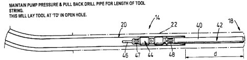
With reference now to Figure 4, a typical logging tool 40 is shown
positioned at the bottom end 18 of the well.
The logging tool 40 has been previously positioned at the head end of the
well and then by usizig the pump fluid pressure in the direction of arrow
26 the logging tool is forced down the drill pipe 20 until the end of the
logging tool reaches the bottom end 18 of the well where its progress is
halted as down in figure 4.
In a preferred example, the logging tool coinprises a first portion 42
4
CA 02290892 1999-11-25
comprising well logging sensors and calliper/drive systems, and a second
portion 44 including a catch portion 46 which acts as a fishing neck.
The second portioaa 44 preferably includes means for allowing controlled
fluid flow 26 thzough said portion fluid passing into openings 47 and out
of openings 48 or vice versa. A full description of the fluid control
section of tool 40 is provided in a co pending application filed on the same
day as the present application and thus this description is hereby
incorporated by way of reference.
t0
The method of operation is as follows and is illustrated by figures 4 to S.
In Figure 4 the logging tool has been forced by fluid flow 26 to the bottom
end 18.
A.
ls Once the logging tool 40 has reached the bottom of the well the tool will
be retained at the end of the drill pipe. The fluid pressure will then begin
to build up on the end of the logging tool. The system is designed to
allow pumping pressure to build to a predetermined limit which in a
preferred embodinient is 100 p.s.i. At this pressure a differential valve
20 (not shown) will open in section 44 of logging tool 40 allowing the
continuation of the flow 26 but now via the tool (see Figure 6).
The fluid flow pressure 26 is maintaiued and the drill pipe 20 is then
inoved back (Figure 5) towards the well head by a distance 'd' (or greater)
25 which causes the logging section 42 of logging tool 40 to pr.otrude from
the bottom end of the drill pipe 20.
The movement of the drill pipe is by conventional means and will not be
described in detail.
5
CA 02290892 1999-11-25
As shown in Figure 6 calliper 45 will open when the logging section 42
of tool 40 ente.rs the borehole 22 and then logging will commence with
drill pipe 20 being pulled at a known rate towards the well head 16.
Caliper control will be by using the Induction measurement and Casing
Col.lar Locator.
Logging of the open borehole 22 will then conti.nue as the drill pipe is
withdrawp, until the casing shoe 23 is reached, at which stage the calliper
arm 45 will close (Figure 7). Again by use of Induction measurement and
io Casing Collar Locator.
The logging operation is then completed with the data being recorded
inside the logging tool 40.
A.
A repeat section can be made once the caliper has closed.
The mud flow '26' is then reversed as indicated by arrows 260 and this
reverse mud flow will lift the tool string incorporating the logging device
40 and the device will be received and captured in holding device 30,23.
?o
With appropriate reverse flow pressures, the tool string 40 may be
received at the well head from a depth of 10,000 ft in approximately 50
minutes data can be downloaded in approximately 10 to 20 minutes.
The method according to the present invention has several advantages over
known systems.
Firstly, by forcing the logging tool to the bottom of the well inside the
drill pipe the tool is protected from any wash-out regions as it passes down
the pipe.
6
CA 02290892 1999-11-25
When the logging tool reaches the end of the drill pipe it is still fully
within the drill pipe. The drill pipe is withdrawn from the logging tool,
the logging tool thereby remaining stationary relative to the well. The
s calliper and the sensoring end of the logging tool will therefore not have
to
be forced into an open bore and therefore will be protected at all times.
By use qf the differential valve means the fluid flow can be maintained
during logging.
7