Language selection

Search

Patent 2290894 Summary

Third-party information liability

Some of the information on this Web page has been provided by external sources. The Government of Canada is not responsible for the accuracy, reliability or currency of the information supplied by external sources. Users wishing to rely upon this information should consult directly with the source of the information. Content provided by external sources is not subject to official languages, privacy and accessibility requirements.

Claims and Abstract availability

Any discrepancies in the text and image of the Claims and Abstract are due to differing posting times. Text of the Claims and Abstract are posted:

  • At the time the application is open to public inspection;
  • At the time of issue of the patent (grant).
(12) Patent: (11) CA 2290894
(54) English Title: WELL LOGGING TOOL
(54) French Title: OUTIL DE DIAGRAPHIE DES SONDAGES
Status: Expired
Bibliographic Data
(51) International Patent Classification (IPC):
  • E21B 47/00 (2012.01)
  • E21B 23/10 (2006.01)
  • E21B 23/14 (2006.01)
  • E21B 34/06 (2006.01)
  • E21B 47/00 (2006.01)
(72) Inventors :
  • MILNE, ALEX WATSON (United Kingdom)
  • SPENCER, MICHAEL CHARLES (United Kingdom)
(73) Owners :
  • REEVES WIRELINE TECHNOLOGIES LTD. (United Kingdom)
(71) Applicants :
  • REEVES WIRELINE TECHNOLOGIES LTD. (United Kingdom)
(74) Agent: BORDEN LADNER GERVAIS LLP
(74) Associate agent:
(45) Issued: 2008-04-29
(22) Filed Date: 1999-11-25
(41) Open to Public Inspection: 2000-05-28
Examination requested: 2003-10-10
Availability of licence: N/A
(25) Language of filing: English

Patent Cooperation Treaty (PCT): No

(30) Application Priority Data:
Application No. Country/Territory Date
9826022.7 United Kingdom 1998-11-28

Abstracts

English Abstract

The well logging tool comprises differential valve means allowing passage of fluid through said tool during logging operations on when the tool becomes jammed inside a drillpipe.


French Abstract

L'outil de diagraphie des sondages comprend des moyens de soupape différentielle permettant le passage du fluide à travers ledit outil lors des opérations d'exploitation forestière ou lorsque l'outil est coincé dans une tige de forage.

Claims

Note: Claims are shown in the official language in which they were submitted.


THE EMBODIMENTS OF THE INVENTION IN WHICH AN EXCLUSIVE
PROPERTY OR PRIVILEGE IS CLAIMED ARE DEFINED AS FOLLOWS:

1. A well logging tool including a fluid flow unit, said fluid flow unit
including differential pressure valve means, said differential pressure valve
means comprising means for allowing passage of fluid from a first inlet grille

means to a second outlet grille means, the differential pressure valve means
being bi-directional to allow passage of fluid through the fluid flow unit in
two directions.

2. A well logging tool as claimed in claim 1 in which the well logging
tool comprises an in use first upper section comprising said fluid flow unit
and an in use second lower section comprising a logging data section
securely attached in longitudinal alignment to said first section.

3. A well logging tool as claimed in claim 2 in which said first and said
second sections of the tool comprise generally elongate cylindrical sections.
4. A well logging tool as claimed in claim 3 in which said first section
comprises at least one enlarged portion, having a diameter larger than the
diameter of the second section.

5. A well logging tool as claimed in claim 4 in which the first section,
includes two enlarged portions, spaced apart on the length of the first
section.
6. A well logging tool as claimed in claim 5 in which said grilles are
situated on a smaller diameter portion of said first section to thereby allow
free passage of said fluid past the logging tool.


6


7. A well logging tool as claimed in claim 6 in which said differential
pressure means comprises a piston slideably mounted in a cylinder, said
piston being spring biased towards a normally closed valve position to
prevent passage of fluid through said cylinder

8. A well logging tool as claimed in claim 7 in which said piston is
movable within the cylinder in two directions to enable fluid paths to be
opened allowing passage of fluid in a first and a second direction.


7

Description

Note: Descriptions are shown in the official language in which they were submitted.


CA 02290894 1999-11-25

WELL LOGGING TOOL

The present invention relates to well logging tools and more particularly to
well logging tools which can be battery operated allowing free rnnvement
s of the tool. The tool could, however, be more conventionally employed
with connecting cable.

It is an object of the present invention to provide a well loggin.g tool which
includes ineans for allowing passage of fluid through the tool.

The prescnt invention provides a well loggiug tool, including a fluid flow
unit, said fluid llow unit including differential pressure valve means, said
differential pressure valve means colnprisiug means for allowing passage
of fluid from a first inlet grille means to a second outlet grille means.
is

In a preferred embodiment the differential pressure valvc means is bi
dircctional allowing passage of fluid through said fluid flow unit in two
directions.

20 Preferably the well logging tool cortiprises a first, in use, upper section
comprising said fluid flow unit and a second in use lower section
conlprising a logging data section securely attached in longitudinal
aligimZcnt to said first section. Preferably said tool and second scctions
comprise generally elongate cylindrical sections.

Preferably said first section comprises at least one enlarged portion,
liaving a diameter larger lhan the diaineter of the second section. In a
preferred embodinient the first section, including two enlarged portions,
spaced apart on the length of the first section.

1


CA 02290894 1999-11-25

Preferably said grilles are situated on a smaller diameter portion of said
first section to thereby allow free passage of said fluid past the logging
tool.


Preferably said differential pressure means comprises a piston slideably
mounted in a cylinder, said piston being spring biased towards a normally
closed valve position to pr.event passage of fluid through said cylinder

Preferably said piston is movable within the cylinder in two directions to
enable fluid parts to be opened allowing passage of fluid in a first and a
sccond direction.

Tn use said first and second directions respectively comprise passage of
i 5 fluid down a drillpipe and upwardly within said drillpipe-

Enlbodiments of the present invention will now be discusscd, by way of
example with reference to the accompanying drawings in which:-

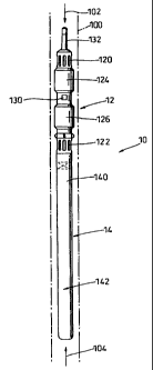
Figure 1 shows diagrammatically a well logging tool in accordaiace
with the preseiit invention,

Figurc 2 shows the fluid flow unit of the well logging tool of figure
1 iu greater detail and,

Figure 3 shows the fluid flow unit of figure 2 in cross sectional
elevation_

Wit1i reference now to figure 1 the well logging tool 10 comprises a
generally elongate cylindrical coaastruction including a first upper section
12 and a second lower section 14. The phrases upper and lower sections
2


CA 02290894 1999-11-25

are used to indicate the normal directional of insertion of the tool 10 into a
borehole (now shown).

The first section 12 comprises a fluid flow unit, the operation of which
will be explained in greater detail with reference to figures 2 and 3.

The second lower section 14 comprises a well data logging section which
may inclu'de a battery and niemory pack section 140 and a calliper/sensor
section 142.
The battery/menaory section 140 enables the logging tool to be free from
any control cables. The logging tool could, however, be connected by a
conventional cable arrangement should this be preferred. Normally,
however, the logging tool will be battery powered.


The data logging sensors and calliper unit may be of conventional designs
which are well known in this art and therefore they will not be described
further.

With reference not to figure 2, the fluid flow unit comprises a first upper
fluid entry/exit port 120 and a second lower fluid entry/exit port 122.
Ad,jacent to the upper fluid entry port 120 is a larger diameter section 124
and adjacent to the lower entry port 122 is a further larger section 126. A
segmenred landing collar 128 is preferably situated between the lower
fluid entry part 122 and the larger diameter section 126.

A differential pressure release valve 130 i:s situated between enlarged
diameter sections 124, 126. A fishing neck 132 is provided at the upper
3


CA 02290894 1999-11-25
end of section 12.

In operation the well logging tool will normally not allow fluid flow
therethrough. Thus when fluid pressure is applied within a drill pipe 100
(shown dotted in flgurc 1) in the direction of arrow 102 the logging tool
will be propclled in that direction and indirection 104 when fluid pressure
is applied in that direction.

01
The ope.ration of the valve means is explaaned with reference to figure 3,
io which shows in cross section the operative part of the first section 12.

The valve means coinprises two cylitlders 142, 144 and a piston 146.
Piston 146 is free to move within the cylinders, but is normally maintained
in a central position as indicated by reference mineral 146 by two coil
springs 148, 150.

Normally piston 146 closes the central portion 152 between cylinders 142,
144 and thus prevents any passage of fluid from griile 120 to grille 122.
Passage of fluid via internal passages 154, 156 is prevented by suitable
seal means 158. Tlius, in normal use fluid pressure in the direction of
arrow 102 will push on the end of 12 of logging tool 10 and cause it,
unless it is obstructed, co move in the direction of arrow 102.

If the logging tool becomes stationary then the fluid flow 102 will be
halted.

In a preferred enibodiment of the fluid pressure in drill pipe 100 reynains
the same as in the loggi g tool transportation made, then piston 146 will
not move substantially.

4


CA 02290894 2006-03-28

However, if pressure is allowed to build up on the side of inlet grille 120
then the differential pressure across piston 146 will increase and this will
then force piston 146 downwardly until it is in position 146.

The fluid flow will then follow arrows 160, 162, 164, 166 allowing fluid to
pass through grilles 120, 121, through cylinders 142, 144 and through grille
123 and outlet grille 122 to pass on down the drill pipe 100.

In like manner, if the fluid flow is reversed, piston 146 will move to the
upper cylinder 142 and the fluid flow through the valve unit will occur in a
reverse direction.

The valve unit therefore allows passage of fluid through the drill pipe at all
times even when logging is occurring as described in GB Patent No. 2 345
502.

5

Representative Drawing
A single figure which represents the drawing illustrating the invention.
Administrative Status

For a clearer understanding of the status of the application/patent presented on this page, the site Disclaimer , as well as the definitions for Patent , Administrative Status , Maintenance Fee  and Payment History  should be consulted.

Administrative Status

Title Date
Forecasted Issue Date 2008-04-29
(22) Filed 1999-11-25
(41) Open to Public Inspection 2000-05-28
Examination Requested 2003-10-10
(45) Issued 2008-04-29
Expired 2019-11-25

Abandonment History

There is no abandonment history.

Payment History

Fee Type Anniversary Year Due Date Amount Paid Paid Date
Registration of a document - section 124 $100.00 1999-11-25
Application Fee $300.00 1999-11-25
Maintenance Fee - Application - New Act 2 2001-11-26 $100.00 2001-10-22
Maintenance Fee - Application - New Act 3 2002-11-25 $100.00 2002-10-21
Request for Examination $400.00 2003-10-10
Maintenance Fee - Application - New Act 4 2003-11-25 $100.00 2003-10-15
Maintenance Fee - Application - New Act 5 2004-11-25 $200.00 2004-10-26
Maintenance Fee - Application - New Act 6 2005-11-25 $200.00 2005-10-26
Maintenance Fee - Application - New Act 7 2006-11-27 $200.00 2006-10-17
Maintenance Fee - Application - New Act 8 2007-11-26 $200.00 2007-10-22
Final Fee $300.00 2008-02-12
Maintenance Fee - Patent - New Act 9 2008-11-25 $200.00 2008-11-05
Maintenance Fee - Patent - New Act 10 2009-11-25 $250.00 2009-10-14
Maintenance Fee - Patent - New Act 11 2010-11-25 $250.00 2010-10-25
Maintenance Fee - Patent - New Act 12 2011-11-25 $250.00 2011-10-13
Maintenance Fee - Patent - New Act 13 2012-11-26 $250.00 2012-10-10
Maintenance Fee - Patent - New Act 14 2013-11-25 $250.00 2013-10-09
Maintenance Fee - Patent - New Act 15 2014-11-25 $450.00 2014-11-05
Maintenance Fee - Patent - New Act 16 2015-11-25 $450.00 2015-11-04
Maintenance Fee - Patent - New Act 17 2016-11-25 $450.00 2016-11-02
Maintenance Fee - Patent - New Act 18 2017-11-27 $450.00 2017-11-01
Maintenance Fee - Patent - New Act 19 2018-11-26 $450.00 2018-09-26
Owners on Record

Note: Records showing the ownership history in alphabetical order.

Current Owners on Record
REEVES WIRELINE TECHNOLOGIES LTD.
Past Owners on Record
MILNE, ALEX WATSON
SPENCER, MICHAEL CHARLES
Past Owners that do not appear in the "Owners on Record" listing will appear in other documentation within the application.
Documents

To view selected files, please enter reCAPTCHA code :


To view images, click a link in the Document Description column. To download the documents, select one or more checkboxes in the first column and then click the "Download Selected in PDF format (Zip Archive)" or the "Download Selected as Single PDF" button.

List of published and non-published patent-specific documents on the CPD .

If you have any difficulty accessing content, you can call the Client Service Centre at 1-866-997-1936 or send them an e-mail at CIPO Client Service Centre.


Document
Description 
Date
(yyyy-mm-dd) 
Number of pages   Size of Image (KB) 
Representative Drawing 2000-05-26 1 4
Drawings 2000-02-28 3 48
Abstract 1999-11-25 1 8
Description 1999-11-25 5 154
Claims 1999-11-25 2 50
Drawings 1999-11-25 3 54
Cover Page 2000-05-26 1 21
Claims 2007-03-22 2 49
Description 2006-03-28 5 150
Claims 2006-03-28 2 49
Representative Drawing 2008-04-08 1 5
Cover Page 2008-04-08 1 27
Prosecution-Amendment 2007-03-22 3 74
Correspondence 1999-12-22 1 2
Assignment 1999-11-25 3 94
Prosecution-Amendment 2000-02-28 4 78
Assignment 2000-03-20 3 88
Prosecution-Amendment 2003-10-10 1 32
Fees 2003-10-15 1 35
Fees 2001-10-22 1 35
Fees 2002-10-21 1 35
Prosecution-Amendment 2004-03-05 2 31
Fees 2004-10-26 1 34
Prosecution-Amendment 2005-09-29 3 84
Fees 2005-10-26 1 37
Prosecution-Amendment 2006-03-28 5 124
Fees 2006-10-17 1 34
Prosecution-Amendment 2007-02-26 1 31
Correspondence 2008-02-12 1 35