Note: Descriptions are shown in the official language in which they were submitted.
CA 02291039 1999-11-23
WO 98/53879 PCT/US98/10741
SYSTEM AND METHOD FOR VENTRICULAR DEFIBRILLATION
Technical Field
The present invention relates generally to implantable medical devices
and in particular to the use of an implantable cardioverter defibrillator for
treating arrhythmias of a patient's heart.
Background of the Invention
Cardiac arrest occurs in more than 500,000 people annually in the United
States, and more than 70% of the out-of hospitals occurrences are due to
cardiac
arrhythmias that are treatable with def brillators. The most serious
arrhythmia
treated by a defibrillator is ventricular fibrillation. Without rapid
treatment using
a defibrillator, ventricular fibrillation causes complete loss of cardiac
function
and death within minutes.
The general mechanism of ventricular fibrillation is chaotic electrical
excitation of the myocardium that results in a loss of coordinated mechanical
contraction characteristic of normal heart beats. These rhythm disorders are
commonly held to be a result of reentrant excitation pathways within the
heart.
The underlying abnormalities that lead to the mechanism are the combination of
conduction block, or resistance, of cardiac excitation waves plus rapidly
recurring depolarization of the membranes of the cardiac cells. This leads to
rapid repetitive propagation of a single excitation wave or of multiple
excitatory
waves throughout the heart. If there are multiple waves, the rhythm may
degrade
into total loss of synchronization of cardiac fiber contraction. Without
synchronized contraction, the chamber affected will not contract, and this is
fatal
when it occurs in the ventricles of the heart. The most common cause of these
conditions, and therefore of these rhythm disorders, is cardiac ischemia or
infarction as a complication of atherosclerosis. The corrective measure is to
stop
the rapidly occurring waves of excitation by simultaneously depolarizing most
of
the cardiac cells with a strong electrical shock. The cells then can
simultaneously repolarizing themselves, and thus they will be back in phase
with
each other.
. ,. .,
CA 02291039 1999-11-23
2
The implantable cardioverter defibrillator (ICD) is a therapeutic device
that can detect ventricular tachycardia or fibrillation and automatically
deliver
strong electrical shocks to restore normal sinus rhythm. The ICD consists of a
primary battery, a high-voltage capacitor, and sensing and control circuitry
housed within a hermetically sealed titanium case. The ICD includes a
transvenous lead system which is implanted into the heart of a patient.
Recognizing that there is variation in the ability of any ICD system to
defibrillate at a particular instant in time is important. The spectrum of
factors
which may contribute to this variability are not fully understood. For
example,
the same setting on an ICD can fail on one attempt but be successful a few
seconds later, with no obvious change in any measured variable. Examples of
attempts include Mower (tJ.S. Pat. No. 4,559,946) which relates to a method
and
apparatus for delivering two or more individual how-level pulses to correct
certain cardiac arrhythmias, and Pless et al. (EP 0674916) which relates to an
1 S apparatus and method for cardiac defibrillation which utilizes a lower
voltage
defibrillation output to depolarize the myocardial cells by providing a rapid
sequence of defibrillation shocks synchronized with sensed sequential cardiac
or
electrogram events or features during an arrhythmia. A need, therefore, exists
to
increase the probability and the efficacy of converting a ventricular
fibrillation
on each ICD defibrillation attempt.
The present invention includes a defibrillator system and a method for
detecting and treating ventricular arrhythmias, including ventricular
fibrillation,
that provides a series of high energy pacing pulses to the cardiac tissue
surrounding a defibrillation electrode prior to delivering a defibrillation
level
shock to the heart. This series of pre-defibrillation electrical pacing pulses
helps
to increase the probability and the efficacy of converting a ventricular
fibrillation
on each defibrillation attempt by preparing the cardiac tissue for
defibrillation in
at least one of two ways. First, the pre-defibrillation electrical pacing
pulses
help to prevent aberrant ventricular contractions from occurring in the region
of
AIVtENDED 5'HEET
CA 02291039 1999-11-23
2/1
a defibrillation electrode shortly after a defibrillation shock has been
delivered.
This results in a reduced likelihood of perpetuating or reinitiate ventricular
fibrillation after a defibrillation pulse has been delivered to the heart.
Second,
the pre-defibrillation electrical pacing pulses can affect coarse ventricular
fibrillation complex signals or coarse ventricular fibrillation electrogram
structures detected by an implantable cardioverter defibrillator. The coarse
ventricular fibrillation complex signals are then used to coordinate the
delivery
of a defibrillation pulse to a heart experiencing a ventricular arrhythmia. As
such, the system and method of the present invention increases the probability
AMFNO~o s~
CA 02291039 1999-11-23
WO 98153879 PCT/US98/10741
3
and the efficacy of converting a ventricular fibrillation with a single
defibrillation shock, resulting in ICDs with longer life, smaller sizes and
less
weight due to a more efficient use of the battery system.
The present invention includes a ventricular catheter releasably attached
to an implantable housing and electronic control circuitry within the
implantable
housing of the defibrillator system for receiving cardiac signals through
ventricular electrodes on the ventricular catheter. The ventricular catheter
has a
ventricular pacing electrode and a first and a second defibrillation electrode
on
its peripheral surface which are electrically connected to the electronic
control
circuitry within the implantable housing. The ventricular catheter is
positioned
within the heart with the ventricular pacing electrode and the first
defibrillation
electrode in the right ventricle chamber of the heart and the second
defibrillation
electrode in a right atrium chamber or a major vein leading to the right
atrium
chamber of the heart.
Upon detecting a ventricular arrhythmia, plurality of electrical pacing
pulses are delivered to the heart. The electrical pulses are high energy
pacing
pulses delivered between the ventricle pacing electrode and the first
defibrillation electrode. Alternatively, the electrical pulses are high energy
pacing pulses delivered between the first and the second defibrillation
electrodes.
These electrical pacing pulses serve to precondition the cardiac tissue
surrounding the first defibrillation electrode so that a subsequent
defibrillation
pulse delivered between the first and second defibrillation electrodes at a
predetermined time after a final electrical pulse will have a higher
probability of
converting a ventricular arrhythmia.
In one embodiment of the present invention there is provided a system
and a method of treating a heart experiencing a ventricular arrhythmia, where
a
region of cardiac tissue surrounding a f rst defibrillation electrode is
preconditioned using plurality of high energy electrical pulses, including a
final
electrical pulse, prior to delivering a defibrillation shock. The
preconditioning of
the region of cardiac tissue reduces the potential of aberrant ventricular
contractions from occurring in the region of cardiac tissue surrounding the
first
defibrillation electrode for a quiescent interval after a defibrillation shock
has
CA 02291039 1999-11-23
WO 98/53879 PCT/US98/10741
4
been delivered. This results in a greater probability of converting a
ventricular
fibrillation on the first attempt.
In an alternative embodiment, the region of cardiac tissue surrounding the
first defibrillation electrode is postconditioned using a plurality of
electrical
pacing pulses after the system has delivered a defibrillation shock to the
heart.
Upon detecting a ventricular fibrillation the system delivers a defibrillation
pulse
to the heart. At a predetermined time after delivering the defibrillation
pulse, the
system delivers the plurality of electrical pacing pulses to the heart. The
electrical pulses are high energy pacing pulses delivered between the
ventricle
I 0 pacing electrode and the first defibrillation electrode. Alternatively,
the
electrical pulses are high energy pacing pulses delivered between the first
and the
second defibrillation electrodes. The postconditioning of the region of
cardiac
tissue reduces the potential of aberrant ventricular contractions from
occurring in
the region of cardiac tissue surrounding the first defibrillation electrode
for a
quiescent interval after the high energy pacing pulses have been delivered.
This
results in a greater probability of converting a ventricular fibrillation on
the first
attempt.
In another embodiment, the system and method of the present invention
treats a heart experiencing a ventricular arrhythmia by applying a plurality
of
electrical pacing pulses to affect the state of coarse ventricular
fibrillation
complex signals. In one aspect of this present embodiment, the plurality of
electrical pacing pulses are delivered to the heart to create a coarse
ventricular
fibrillation complex signals. Alternatively, in another aspect of this present
embodiment, the plurality of electrical pacing pulses are delivered
synchronously
with a detected coarse ventricular fibrillation complex signal to maintain or
increase the coarseness of the coarse ventricular fibrillation complex
signals.
The coarse ventricular fibrillation complex signals are then used to
coordinate the delivery of the defibrillation level shock, where the delivery
of the
defibrillation shock is coordinated to an upslope portion of a coarse
ventricular
fibrillation complex signals. In an alternative embodiment, the occurrence of
coarse ventricular fibrillation complex signals are counted, and the delivery
of
the defibrillation shock is coordinated with a predetermined portion of the
CA 02291039 1999-11-23
upslope of a predetermined numbered occurrence of coarse ventricular
fibrillation
complex signals, where the predetermined numbered occurrence of coarse
ventricular
fibrillation complex signals is greater than or equal to 2 and less than or
equal to about
9.
According to an aspect of the invention, a method, comprising the acts of
sensing signals representative of ventricular electrical activity, wherein the
Improvement comprises:
controlling the state of coarse ventricular fibrillation complexes by
delivering
a plurality of pacing pulses.
According to another aspect of the invention, a method, comprising the acts of
sensing signals representative of ventricular electrical activity;
delivering a plurality of pacing pulses during an occurrence of ventricular
fibrillation, the plurality of pacing pulses being delivered sequentially at a
programmed voltage; and
delivering a defibrillation shock at a predetermined time after the plurality
of
pacing pulses.
According to a further aspect of the invention, a system, comprising:
a ventricular catheter including a first ventricular pacing electrode and a
first
defibrillation electrode; and
electronic control circuitry connected to the first ventricular pacing
electrode
and the first defibrillation electrode, where the electronic control circuitry
senses
signals representative of ventricular electrical activity through the first
ventricular
pacing electrode and the first defibrillation electrode, and delivers a
plurality of
pacing pulses through the ventricular catheter to control the state of coarse
ventricular
fibrillation complexes.
Brief Description of the Drawings
Figure 1 is a schematic diagram of one embodiment of a defibrillator system,
including an implantable cardioverter defibrillator with a ventricular lead,
implanted
in a human heart from which segments have been removed to show details;
Figure 2 is a block diagram of one embodiment of the implantable
cardioverter defibrillator with which the present invention may be
implemented,
including a diagrammatic representation of a ventricular lead placed in the
heart;
Figure 3 is a waveform of a morphology signal from a heart in ventricular
fibrillation (VF);
CA 02291039 1999-11-23
Sa
Figure 4 is a flow chart illustrating one embodiment of a mode of operation of
the defibrillator system of Figure 1 in detecting and treating a ventricular
arrhythmia;
Figure 5 is a waveform of a morphology signal from a heart in VF being
treated by one embodiment of a method of the present invention;
Figure 6 is a flow chart illustrating one embodiment of a mode of operation of
the defibrillator system of Figure 1 in detecting and treating a ventricular
arrhythmia;
Figure 7 is a waveform of a morphology signal from a heart in VF being
treated by one embodiment of a method of the present invention;
Figure 8 is a flow chart illustrating one embodiment of a mode of operation of
the defibrillator system of Figure 1 in detecting and treating a ventricular
arrhythmia;
Figure 9 is a waveform of a morphology signal from a heart in VF;
Figure 10 is a waveform of a morphology signal from a heart in VF being
treated by one embodiment of a method of the present invention;
Figure 11 is a waveform of a morphology signal from a heart in VF being
treated by one embodiment of a method of the present invention;
CA 02291039 1999-11-23
6
Figure 12 is a flow chart illustrating one embodiment of a mode of
operation of the defibrillator system of Figure 1 in detecting and treating a
ventricular arrhythmia; and
Figure 13 is a flow chart illustrating one embodiment of a mode of
operation of the defibrillator system of Figure 1 in detecting and treating a
ventricular arrhythmia.
In the following detailed description, reference is made to the
accompanying drawings which form a part hereof and in which is shown by way
of illustration specific embodiments'in which the invention may be practiced.
The following detailed description is, therefore, not to be taken in a
limiting
sense and the scope of the present invention is defined by the appended claims
and their equivalents.
The embodiments of the present invention illustrated herein are described
as being included in an implantable cardioverter defibrillator, which may
include
numerous pacing modes as are known in the art. The system and method of the
present invention could also be implemented in an external
defibrillator/monitor.
Referring now to Figures 1 and 2 of the drawings, there is shown a
defibrillator system 10 including an iinplantable cardioverter defibrillator
12
k,
physically and electrically coupled to a ventricular catheter 14, which the
defibrillator system 10 may use in practicing the method according to the
present
invention. The defibrillator system 10 is implanted in a human body 16 with
portions of the ventricular catheter 14 inserted into a heart 18 to detect and
analyze electric cardiac signals produced by the ventricles 20 of the heart 18
and
to provide electrical energy to the heart 18 under certain predetermined
conditions to treat ventricular arrhythmias, including ventricular
fibrillation, of
the heart 18.
AM~ND~D SHEET
CA 02291039 1999-11-23
WO 98153879 1'CT/US98/10741
7
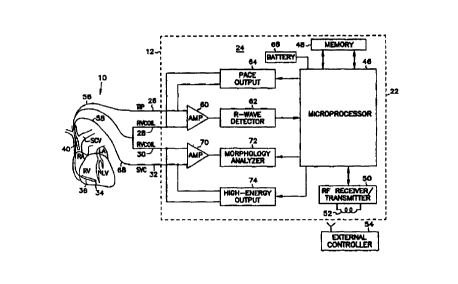
A schematic of the defibrillator 12 electronics is shown in Figure 2. The
system for defibrillating a heart 18 has an implantable cardioverter
defibrillator
12 comprising an implantable housing 22 which contains electronic control
circuitry 24. The electronic control circuitry 24 includes terminals, labeled
with
reference numbers 26, 28, 30 and 32, for connection to the ventricular
catheter
14.
The ventricular catheter 14 is an endocardial lead, although other types
could also be used within the scope of the invention. The ventricular catheter
14
is adapted to be releasably attached to the implantable housing 22 of the
defibrillator system 10. The ventricular catheter 14 is shown as having a
first
ventricular pacing electrode 34 located at, or adjacent, the distal end of the
ventricular catheter 14, which is connected electrically through a conductor
provided in the ventricular catheter 14, for connection to terminal 26 and to
the
electronic control circuitry 24. The ventricular catheter 14 also includes a
first
i 5 defibrillation electrode 36 and a second defibrillation electrode 40 both
connected to the electronic control circuitry 24. In one embodiment, the first
defibrillation electrode 36 and the second defibrillation electrode 40 are
defibrillation coil electrodes as are known in the art.
The first defibrillation electrode 36 is positioned on the ventricular
catheter 14 and a distance back from the first ventricular pacing electrode 34
such that when the ventricular catheter 14 is positioned within the heart 18
the
first ventricular pacing electrode 34 and the first defibrillation electrode
36 are
positioned in the right ventricle 38 of the heart I 8 , with the first
ventricular
pacing electrode 34 in an apex location within the right ventricle 38. The
first
defibrillation electrode 36 connects through internal conductors in the lead
and is
connected both to terminals 28 and 30 and to the electronic control circuitry
24.
The second defibrillation electrode 40 is positioned a distance back from the
first
defibrillation electrode 36 such that the second defibrillation electrode 40
is in a
right atrium chamber 42 or a major vein 44 leading to the right atrium chamber
42 of the heart 18 . The second defibrillation electrode 40 connects through
internal conductors in the ventricular catheter 14 and is connected to
terminal 32.
CA 02291039 1999-11-23
WO 98/53879 PCT/US98/10741
8
The def brillator 12 is a programmable microprocessor-based system,
with a microprocessor indicated by reference number 46. Microprocessor 46
operates in conjunction with a memory 48, which contains parameters for
various pacing and sensing modes. Microprocessor 46 includes means for
communicating with an internal controller, in the form of an RF
receiver/transmitter 50. This includes a wire loop antenna 52, whereby it may
receive and transmit signals to and from an external controller 54. In this
manner, programming inputs can be applied to the microprocessor 46 of the
defibrillator 12 after implant, and stored data on the operation of the system
in
response to patient needs can be read out for medical analysis.
In the defibrillator 12 of Figure l, the first ventricle pacing electrode 34
and the first defibrillation electrode 36, connected through leads 56 and 58,
are
applied to a sense amplifier 60, whose output is shown connected to an R-wave
detector 62. These components serve to sense and amplify the QRS wave of the
heart, and apply signals indicative thereof to the microprocessor 46. Among
other things, microprocessor 46 responds to the R-wave detector 62, and
provides pacing signals to a pace output circuit 64, as needed according to
the
programmed pacing mode. Pace output circuit 64 provides output pacing signals
to terminals 26 and 28, which connect as previously indicated to the first
ventricular pacing electrode 34 and the first defibrillation electrode 36, for
normal pacing and pacing according to the present invention. In an alternative
embodiment, the pace output circuit 64 can provide output pacing signals to
terminals 30 and 32 (not shown), which connects as previously indicated to the
first defibrillation electrode 36 and the second defibrillation electrode 40
for
delivering normal pacing and pacing according to the present invention.
The first and the second defibrillation electrodes 36 and 40, connected
through leads 58 and 68, are applied to a sense amplifier 70, whose output is
shown connected to a morphology analyzer 72 and the microprocessor 46. These
components serve to sense, amplify and analyze the morphology of the QRS
wave of the heart. Among other things, microprocessor 46 responds to the
morphology analyzer 72, and provides signals to a high-energy output circuit
74
and the pace output circuit 64 to provide pacing and defibrillation level
electrical
CA 02291039 1999-11-23
WO 98153879 PCT/US98110741
9
energy to the heart as needed according to the method and system of the
present
invention. Power to the implantable cardioverter defibrillator 12 is supplied
by
an electrochemical battery 66 that is housed within the implantable
cardioverter
defibrillator 12.
The electronic control circuitry 24 receives cardiac signals through the
ventricle electrodes 34, 36 and 40, and delivers, upon detecting a ventricular
arrhythmia, plurality of electrical pacing pulses to the heart and a
defibrillation
pulse at a predetermined time after a final electrical pulse. In the
embodiment
shown in Figure 1, the ventricular catheter 14 and the electronic control
circuitry
24 are utilized for sensing the rate and morphology signals from the
ventricular
activity. Unipolar and/or bipolar pacing and ventricular rate sensing can be
used in conjunction with the first ventricular pacing electrode 34 and the
first
defibrillation electrode 36 of the ventricular catheter 14. Ventricular
activity is
determined by sensing for the occurrence of ventricular R-waves. The first
15 ventricular pacing electrode 34 can be used for either unipolar rate
sensing
between the first ventricular pacing electrode 34 and the implantable housing
22,
or bipolar rate sensing between the first ventricular pacing electrode 34 and
the
first defbrillation electrode 36. Ventricular morphology signals can be sensed
between the first and the second defibrillation electrodes 36 and 40, where
the
20 electrodes are coupled through the sense amplifier 70 to the morphology
analyzer
72 and the microprocessor 46 to assess and analyze the morphology of the
sensed
ventricular signals. In an alternative embodiment, it is also possible to
detect
unipolar cardiac morphology signals between the first defibrillation electrode
36
and the implantable housing 22. Pacing therapies (bipolar or unipolar) are
delivered to the ventricles 20 of the heart 18 using these same electrodes.
The defibrillator 12 further includes a high-energy output circuit 74,
which operates under the control of the microprocessor 46, as indicated. The
high-energy output circuit 74 is connected to the first and second
defibrillation
electrode terminals 30 and 32, which connects to the first and second
defibrillation electrodes 36 and 40 as previously mentioned. In this manner,
defibrillation pulses can be delivered between the first defibrillation
electrode 36
CA 02291039 1999-11-23
WO 98/53879 PCT/US98/10741
and the second defibrillation electrode 40 when called for by the
microprocessor,
and specifically the software implementation of control algorithms.
In an alternative embodiment, the implantable housing 22 of the
defibrillator system 10 can be a defibrillation electrode, where the
implantable
5 housing 22 of the implantable cardioverter defibrillator 12 has an exposed
electrically conductive surface that is electrically connected to the high-
energy
output circuit 74, such that the plurality of electrical pulses to the heart
18 are
high energy pacing pulses delivered between the first ventricle pacing
electrode
34 and the first defibrillation electrode 36, and the defibrillation pulse is
10 delivered between the first defibrillation electrode 36 and the exposed
electrically conductive surface of the implantable housing 22. Alternatively,
defibrillation pulses can be delivered between either of the defibrillation
electrodes 36 or 40 and the implantable housing 22 of the implantable
defibrillator system 10, or between any combination of the two def brillation
electrodes 36 and/or 40 and the implantable housing 22 of the implantable
defibrillator system 10.
Besides the lead configuration shown in Figure 1, the defibrillator system
I 0 supports several other lead configurations and types. For example it is
possible to use ventricular epicardial rate sensing, atrial endocardial
bipolar
pace/sensing, ventricular endocardial bipolar pace/sensing, epicardial
patches,
and ancillary leads in conjunction with the implantable cardioverter
defibrillator
12.
The ventricular catheter 14 is releasably attached to and are separated
from the implantable cardioverter defibrillator 12 to facilitate inserting the
ventricular catheter 14 into the heart 18 . The ventricular catheter i 4 is
inserted
into the heart 18 transvenously through a cephalic or subclavian vein (not
shown} to position the distal end of the ventricular catheter 14 in the apex
of the
right ventricular chamber 38. The proximal end of the ventricle catheter 14 is
then attached to the implantable cardioverter defibrillator 12. The proximal
end
of the ventricular catheter 14 is adapted to seal together with the terminals
26,
28, 30 and 32 of the implantable cardioverter defibrillator 12 to thereby
engage
the ventricular catheter 14 leads with the electronic control circuitry 24 of
the
CA 02291039 1999-11-23
WO 98/53879 PCT/US98110741
11
implantable cardioverter defibrillator 12. The implantable cardioverter
defibrillator 12 of the defibrillator system 10 is then positioned
subcutaneously
within the body 16.
Referring now to Figure 3 there is shown a schematic of an
electrocardiogram of a heart experiencing ventricular fibrillation. At 80 of
Figure 3 there is shown the electrocardiogram of the ventricular fibrillation
prior
to defibrillation treatment by a defibrillator system. As the ventricular
fibrillation progresses the electrocardiogram shows an asynchronous
defibrillation shock being delivered at 82 to the heart 18 . The total amount
of
current delivered to the heart is important for defibrillation. However, how
that
current is distributed throughout the heart can be even a more important
factor
for defibrillation. Different amounts of current flow through different parts
of
the heart during a shock. For shocks delivered from intracardiac electrodes,
the
distribution of potential gradients is highly uneven. High potential gradients
occur near the defibrillation electrodes (known as "high field" areas), and
low
potential gradients occur in those cardiac regions distant from the
defibrillation
electrodes (known as "low field" areas).
For defibrillation shocks delivered through transvenous electrodes
ectopic activation fronts first appear following the shock in regions exposed
to
the highest potential gradients generated by the shocks. These high potential
gradient regions are adjacent to the defibrillation electrodes. It is
suggested that
defibrillation shocks delivered by a defibrillation system.that fail to
convert a
ventricular fibrillation are due in part to these aberrant activation fronts
arising
from the high potential gradient regions that reinduce ventricular
fibrillation
shortly after a defibrillation pulse has been delivered to the heart. These
ectopic
activation fronts, or extra beats, are seen in Figure 3 at 84. The aberrant
ventricular contractions, or beats, impinge on areas of the ventricular
myocardium that the defibrillation shock has weakly effected, and are believed
to
contribute to reinducing and/or continuing the ventricular fibrillation 86. As
a
result, additional defibrillation shocks are required to restore sinus rhythm.
Referring now to Figure 4, there is shown a flow diagram of an
embodiment of the method used by the defibrillator system 10 for treating a
CA 02291039 1999-11-23
WO 98/53879 PCT/US98110741
12
ventricular arrhythmia of a patient's heart 18. The embodiment reduces the
potential of aberrant post-defibrillation ventricular contractions, such as
those
seen at 89 in Figure 3, from occurring in the cardiac region surrounding the
first
defibrillation electrode 36 by providing preconditioning electrical energy
pacing
pulses that create a post-defibrillation quiescent interval of time. Initially
at 100,
the defibrillator system 10 utilizes the ventricular catheter 14 for sensing
the
ventricular cardiac signals of the heart 18 . The electronic control circuitry
24
receives either unipolar or bipolar rate and morphology cardiac signals
through
the ventricular electrodes 34, 36 and 40. The sensed cardiac signals are then
analyzed by the electronic control circuitry 24 of the defibrillator system 10
at
102 to determine if the heart is experiencing a ventricular arrhythmia. In
this
context a ventricular arrhythmia can include ventricular tachyarrythmia and
ventricular fibrillation.
In analyzing the cardiac signals at 102, the electronic control circuitry 24
of the defibrillator system 10 determines the occurrence and/or presence of a
ventricular arrhythmias by analyzing the morphology of the R-waves detected by
the defibrillator system 10 and the rate relation of the ventricular R-waves
to
preprogrammed ventricular rate and rate acceleration parameters.
During 102, if the heart is not experiencing a ventricular arrhythmia, the
defibrillator system 10 returns to 100, via 104, to analyze the next series of
sensed ventricular intervals. However, if a ventricular arrhythmia is detected
at
102, the defibrillator system 10 then proceeds to 106 where the electronic
control
circuitry 24 of the defibrillator system 10 functions to deliver plurality of
preconditioning pulses of electrical energy to the region of cardiac tissue
surrounding the first defibrillation electrode 36 (the "high field" area),
including
a final electrical pulse delivered at 108, so that the myocardium surrounding
the
first defibrillation electrode 36 will be quiescent for a quiescent interval
period
of time following the defibrillation shock.
In the present embodiment, the pacing pulses are high energy pacing
pulses delivered either between the first ventricular pacing electrode 34 and
the
first defibrillation electrode 36, or between the first and the second
defibrillation
electrodes 36 and 40. These pre-conditioning pulses function to "stun" or
render
CA 02291039 1999-11-23
WO 98/53879 PCT/US98/10741
13
inactive the myocardium in the "high field" area surrounding the first
defibrillation electrode 36 just prior to delivering a defibrillation shock so
that no
aberrant ventricular contractions can arise from this area for the quiescent
interval period of time after the defibrillation shock has been delivered. The
quiescent interval period of time created by the preconditioning pulses of
electrical energy is sufficient in duration to allow the sinoatrial node, or
an
implanted pacemaker, to establish sinus rhythm once again.
To precondition the myocardium, the electronic control circuitry 24 of
the defibrillator system 10 delivers high energy pacing pulses to the heart
through the ventricular catheter 14, as previously described, where the high
energy pacing pulses are delivered at a programmed voltage of between 1 - 20
volts. In an alternative embodiment, the high energy pacing pulses are
delivered
at an amplitude of between 5 - 20 times the diastolic threshold of the
patient.
The electronic control circuitry 24 of the system is also programmed to
deliver
the high energy pacing pulses in a sequential series of between 10 - 200 high
energy pacing pluses, at a predetermined interpulse interval of between 10 -
40,
15 - 35, or 20 - 30 milliseconds, where 20 milliseconds is a suitable value.
In an alternative embodiment, the high energy pacing pulses are delivered
at a programmed current level of between 0.1 - 3 amperes, where the pre-
conditioning electrical energy pulses delivered between the first and the
second
defibrillation electrodes 36 and 40 are between 1 - 3 amperes, with 2 amperes
being a suitable value, or, alternatively, where the pre-conditioning
electrical
energy pulses delivered between the first ventricular pacing electrode 34 and
the
first defibrillation electrode 36 are between 0.1 - 0.3 amperes, with 0.2
amperes
being a suitable value. In an additional embodiment, the plurality of
electrical
pulses delivered to pre-condition the heart are cardioversion level pulses of
electrical energy.
After the cardiac tissue has been preconditioned, the defibrillator system
10 at 1 I 0 delivers a defibrillation shock at a predetermined time after the
final
electrical pulse, where the predetermined time of delivering a defibrillation
level
shock is a programmable value between 10 - 200 milliseconds. However,
defibrillation pulses delivered to the heart after a final electrical pulse is
not
CA 02291039 1999-11-23
WO 98/53879 PCT/US98/10741
14
necessarily limited to this coupling time range because it is recognized that
the
quiescent interval of time can result from the preconditioning pulses even
when
the time between the final electrical pulse and the defibrillation shock is
greater
than 200 milliseconds. After delivering the defibrillation level shock at 110,
the
defibrillator system 10 returns to 100, via 112, to analyze the next series of
sensed ventricular intervals.
Referring now to Figure 5, there is shown a schematic of an
electrocardiogram of a heart experiencing a ventricular fibrillation treated
by the
present embodiment of the method and system of the invention. At 120, the
electrocardiogram indicates that the heart I8 is experiencing a ventricular
fibrillation. The ventricular fibrillation is detected by the electronic
control
circuitry 24 of the defibrillator system 10, and responds by beginning to
charge
both a pacing discharge capacitor associated with the pace output circuit 64,
and
a defibrillation discharge capacitor associated with the high-energy output
circuit
74. The pacing discharge capacitor is charged to a level of approximately 100
volt at which point the pace output circuit 64 delivers, by way of example, a
series of ten (10) pre-conditioning high-energy pacing pulses at 122.
The high energy pacing pulses are delivered across either the first
ventricular pacing electrode 34 or tie first defibrillation electrode 36 at a
preset
interpulse interval of 20 milliseconds. In one embodiment, the pacing
capacitor
of the pace output circuit 64 is not concurrently recharged during the
delivery of
the high energy pacing pulses. As a result, the voltage of subsequent pacing
pulses delivered during treatment of a ventricular fibrillation is at or below
the
voltage of the pacing pulse just previously delivered. Finally, after a final
electrical pulse has been delivered to the heart 18 , the defibrillator system
10
terminates the ventricular arrhythmia at 124 by delivering a
cardioversionldefibrillation pulse of electrical energy through the
ventricular
defibrillation electrode and across the ventricular region of the heart 18 at
a
predetermined time after the final electrical pulse. Figure S indicates that
as a
result of preconditioning the heart 18 with the high energy pacing pulses, the
potential for aberrant ventricular contractions in the "high field" area
surrounding the first defibrillation electrode 36 is reduced as a quiescent
interval
CA 02291039 1999-11-23
WO 98/53879 PCT/US98l10741
of time is created at 126. This quiescent interval of time allows the heart I
8 to
once again fall under the control of the sinoatrial-node and/or the pacemaker
of
the implantable defibrillator system 10 and restore sinus rhythm as seen at
128.
Referring now to Figure 6, there is shown a flow diagram of an
5 alternative embodiment of the method used by the defibrillator system 10 for
treating a ventricular arrhythmia of a patient's heart 18 . The embodiment
reduces the potential of aberrant post-defibrillation ventricular
contractions, such
as those seen at 89 in Figure 3, from occurring in the cardiac region
surrounding
the first defibrillation electrode 36 by providing postconditioning electrical
10 energy pacing pulses to a patient's heart after a defibrillation level
shock has
been delivered that create a post-defibrillation quiescent interval of time.
Initially at 130, the defibrillator system 10 utilizes the ventricular
catheter 14 for
sensing the ventricular cardiac signals of the heart 18 . The electronic
control
circuitry 24 receives either unipolar or bipolar rate and morphology cardiac
15 signals through the ventricular electrodes 34, 36 and 40. The sensed
cardiac
signals are then analyzed by the electronic control circuitry 24 of the
defibrillator
system 10 at 132 to determine if the heart is experiencing a ventricular
arrhythmia. In this context a ventricular arrhythmia can include ventricular
tachyarrythmia and ventricular fibrillation.
In analyzing the cardiac signals at 132, the electronic control circuitry 24
of the defibrillator system 10 determines the occurrence and/or presence of a
ventricular arrhythmias by analyzing the morphology of the R-waves detected by
the defibrillator system 10 and the rate relation of the ventricular R-waves
to
preprogrammed ventricular rate and rate acceleration parameters.
During 132, if the heart is not experiencing a ventricular arrhythmia, the
defibrillator system 10 returns to 130, via 134, to analyze the next series of
sensed ventricular intervals. However, if a ventricular arrhythmia is detected
at
132, the defibrillator system 10 then proceeds to 136 where the electronic
control
circuitry 24 of the defibrillator system 10 functions to deliver a
defibrillation
level shock to the heart.
At a predetermined time after delivering the defibrillation level shock to
the heart, the defibrillation system 20 delivers a plurality of
postconditioning
CA 02291039 1999-11-23
WO 98/53879 PCTIUS98I10741
16
pulses of electrical energy at 138 to the region of cardiac tissue surrounding
the
first defibrillation electrode 36 (the "high field" area) so that the
myocardium
surrounding the first defibrillation electrode 36 will be quiescent for a-
quiescent
interval period of time following a final postconditioning pacing pulse of
electrical energy. The predetermined time of delivering the plurality of
postconditioning pulses of electrical energy after delivering the
defibrillation
level shock is a programmable value between 10 - 100 milliseconds. However,
the plurality of postconditioning pulses delivered after the defibrillation
level
shock is not necessarily limited to this coupling time range, and
predetern~ined
times of greater than 100 milliseconds are considered to be within the scope
of
the invention. After delivering the final postconditioning pacing pulse of
electrical energy at 138, the defibrillator system 10 returns to 130, via 140,
to
analyze the next series of sensed ventricular intervals.
In the present embodiment, the pacing pulses are high energy pacing
pulses delivered either between the first ventricular pacing electrode 34 and
the
first defibrillation electrode 36, or between the first and the second
defibrillation
electrodes 36 and 40. These postconditioning pulses function to "stun" or
render
inactive the myocardium in the "high field" area surrounding the first
defibrillation electrode 36 just after delivering a defibrillation shock so
that no
aberrant ventricular contractions can arise from this area for the quiescent
interval period of time after the final postconditioning pacing pulse has been
delivered. The quiescent interval period of time created by the
postconditioning
pulses of electrical energy is sufficient in duration to allow the sinoatrial
node, or
an implanted pacemaker, to establish sinus rhythm once again.
To postcondition the myocardium, the electronic control circuitry 24 of
the defibrillator system 10 delivers high energy pacing pulses to the heart
through the ventricular catheter 14, as previously described, where the high
energy pacing pulses are delivered at a programmed voltage of between 1 - 20
volts. The electronic control circuitry 24 of the system is also programmed to
deliver the high energy pacing pulses in a sequential series of between 5 -
200
high energy pacing pluses, at a predetermined interpulse interval of between
10 -
40, 15 - 25, or 20 - 30 milliseconds, where 20 milliseconds is a suitable
value.
CA 02291039 1999-11-23
WO 98153879 PCT/US98/10741
17
In an alternative embodiment, the high energy pacing pulses are delivered
at a programmed current level of between 0.1 - 3 amperes, where the post-
conditioning electrical energy pulses delivered between the first and the
second
defibrillation electrodes 36 and 40 are between 1 - 3 amperes, with 2 amperes
being a suitable value, or, alternatively, where the post-conditioning
electrical
energy pulses delivered between the first ventricular pacing electrode 34 and
the
first defibrillation electrode 36 are between 0.1 - 0.3 amperes, with 0.2
amperes
being a suitable value. In an additional embodiment, the plurality of
electrical
pulses delivered to post-condition the heart are cardioversion level pulses of
electrical energy.
Referring now to Figure 7, there is shown a schematic of an
electrocardiogram of a heart experiencing a ventricular fibrillation treated
by the
present embodiment of the method and system of the invention. At 142, the
electrocardiogram indicates that the heart 18 is experiencing a ventricular
fibrillation. The ventricular fibrillation is detected by the electronic
control
circuitry 24 of the defibrillator system 10, and responds by beginning to
charge
both a pacing discharge capacitor associated with the pace output circuit 64,
and
a defibrillation discharge capacitor associated with the high-energy output
circuit
74
At 144, the defibrillator system 10 delivers a cardioversion/defibrillation
pulse of electrical energy through the ventricular defibrillation electrode
and
across the ventricular region of the heart 18. At a predetermined time after
the
defibrillation pulse of electrical energy is delivered to the heart, the pace
output
circuit 64 delivers, by way of example, a series of five (5) post-conditioning
high-energy pacing pulses at 146.
The high energy pacing pulses are delivered across either the first
ventricular pacing electrode 34 or the first defibrillation electrode 36 at a
preset
interpulse interval of 20 milliseconds. In one embodiment, the pacing
capacitor
of the pace output circuit 64 is not concurrently recharged during the
delivery of
the high energy pacing pulses. As a result, the voltage of subsequent pacing
pulses delivered during treatment of a ventricular fibrillation is at or below
the
voltage of the pacing pulse just previously delivered.
CA 02291039 1999-11-23
. . 18
0
Figure 5 indicates that as a result of postconditioning the heart 18 with
the high energy pacing pulses, the potential for aberrant ventricular
contractions
in the "high field" area surrounding the first defibrillation electrode 36 is
reduced
as a quiescent interval of time is created at 148. This quiescent interval of
time
allows the heart 18 to once again fall under the control of the sinoatrial-
node
and/or the pacemaker of the implantable defibrillator system 10 and restore
sinus
rhythm as seen at 150.
Referring now to Figure 8 there is shown an alternative embodiment of
the present invention to treat ventricular arrhythmias, including ventricular
fibrillation, by providing a series of electrical pacing pulses to the cardiac
tissue
surrounding the first defibrillation electrode 36 prior to delivering a
defibrillation
level shock to the heart 18 . The present embodiment of the invention relates
to
the copending U.S. Patent Application Serial Nod' 08/513,685, filed August 11,
1995, and the copending U.S. Patent Application entitled " IMPROVED
METHOD AND APPARATUS FOR TREATING CARDIAC ARRHYTHMIA
USING ELECTROGRAM FEATURES", filed May 6, 1997. The present
embodiment of the method and defibrillation system of the invention delivers a
series of pre-defibrillation electrical pacing pulses to increase the
probability and
the efficacy of converting a ventricular fibrillation by preparing the cardiac
tissue
for defibrillation by affecting~coarse ventricular fibrillation complex
signals.
The coarse ventricular fibrillation complex signals are then used to
coordinate
the delivery of a defibrillation pulse to a heart experiencing a ventricular
arrhythmia, as more fully described in the~aforementioned U.S. Patent
Applications.
The method of the present embodiment treats a heart experiencing
ventricular fibrillation by first applying a plurality of electrical pulses is
to
affect the state of coarse ventricular fibrillation complex signals. The term
"affected", as used in conjunction with the state of coarse ventricular
fibrillation
complex signals, means to produce a material influence upon or alteration in
the
cardiac electrogram signals that are sensed during a ventricular fibrillation.
In
this way the plurality of electrical pacing pulses are used to affect the
state of
coarse ventricular fibrillation complex signals by creating coarse ventricular
fibrillation
AMENDED SHEET
CA 02291039 1999-11-23
WO 98/53879 PCT/US98/10741
19
complex signals. Subsequent pacing pulses delivered after the creation of a
coarse ventricular fibrillation complex signal can then be coordinated to up-
slope
portions of the detected coarse ventricular fibrillation signals to further
coarsen
the ventricular signal.
In an alternative embodiment, if coarse ventricular fibrillation complex
signals are initially detected, the plurality of electrical pacing pulses are
used to
affect the state of coarse ventricular fibrillation complex signals by
synchronizing there delivery with the coarse ventricular fibrillation complex
signals to maintain or increase the coarseness of the coarse ventricular
fibrillation complex signals. This is accomplished by delivering the pacing
pulses during the up-slope portion of the sensed coarse ventricular
fibrillation
complex signal.
Referring now to Figure 8, there is shown a flow diagram of an
embodiment of a method used by the defibrillator system 10 for treating a
ventricular arrhythmia of a patient's heart 18 . The embodiment of the present
invention utilizes preconditioning pacing pulses to create coarse ventricular
fibrillation complex signals upon which the defibrillator system 10 can
coordinate the delivery of a defibrillation shock. The goal in providing the
preconditioning pacing pulses is to disturb, affect, and/or reset a large
portion of
the ventricular tissue during a ventricular fibrillation. Initially at 170,
the
defibrillator system 10 utilizes the ventricular catheter 14 for sensing the
ventricular cardiac signals of the heart I 8 . The electronic control
circuitry 24
receives either unipolar or bipolar rate and morphology cardiac signals
through
the ventricular electrodes 34, 36 and 40. The sensed cardiac signals are then
analyzed by the electronic control circuitry 24 of the defibrillator system 10
at
172 to determine if the heart 18 is experiencing a ventricular arrhythmia. In
this
context a ventricular arrhythmia can include ventricular tachyarrythmia and
ventricular fibrillation.
In analyzing the cardiac signals at 172, the electronic control circuitry 24
of the defibrillator system 10 can determine the occurrence and/or presence of
a
ventricular arrhythmias by analyzing the morphology of the R-waves detected by
CA 02291039 1999-11-23
WO 98/53879 PCT/US98/10741
the defibrillator system I O and the rate relation of the ventricular R-waves
to
preprogrammed ventricular rate and rate acceleration parameters.
During 172, if the heart is not experiencing a ventricular arrhythmia, the
defibrillator system 10 returns to 170, via 174, to analyze the next series of
S sensed ventricular intervals. However, if a ventricular arrhythmia is
detected at
172, the defibrillator system 10 then proceeds to 176 where the electronic
control
circuitry 24 of the defibrillator system 10 functions to deliver plurality of
pulses
of electrical energy, including a final electrical pulse delivered at 178, to
the
region of cardiac tissue surrounding the first defibrillation electrode 36 to
10 precondition the heart so that coarse ventricular fibrillation complex
signals are
created, or pre-existing coarse ventricular fibrillation complex signals are
coarsened, in the ventricular morphology signals sensed by the defbrillator
system 10.
Figure 9 illustrates a morphology signal such as would be detected by the
I S sense amplifier 70, from a first signal appearing across the first
defibrillation
electrode 36 and the second defibrillation electrode 40 on the ventricular
catheter
14. For other types of lead systems, similar or corresponding signals would be
present.
In Figure 9 Zones F1 and F2 show regions of fne ventricular fibrillation.
20 Zones C 1 and C2 show coarse ventricular fibrillation complex signals.
Within
complex C1, a single peak feature of the complex is indicated by reference
number 200. The difference in amplitude between the amplitude extremes, 202
and 204, indicates the peak-to-peak amplitude calculation which is used as a
part
of the method of the invention. In the aforementioned Patent Applications the
system senses and analyzes coarse ventricular fibrillation complex signals as
they naturally occur during the course of a ventricular fibrillation. In
contrast to
this approach, the present invention delivers pacing pulses to cardiac tissue
experiencing ventricular fibrillation to create or coarsen coarse ventricular
fibrillation complex signals on which the defibrillator system 10 of the
present
invention can coordinate the delivery of a defibrillation shock to the heart
18 .
Figures i 0 and 11 are examples of coarse ventricular fibrillation complex
signals being created or coarsened by the preconditioning pacing pulses
CA 02291039 1999-11-23
WO 98/53879 PCT/US98/10741
21
delivered at step 176 of Figure 8. F3 and F4 show regions of fine ventricular
fibrillation which are sensed and analyzed by the defibrillator system 10.
Upon
detecting a ventricular fibrillation, the defibrillator system 10 proceeds to
deliver
plurality of preconditioning pacing pulses. In Figure 10, four preconditioning
pacing pulses are delivered to the heart 18 starting at 206. The
preconditioning
pacing pulses have the effect of creating a coarse ventricular fibrillation
complex
signal C3 by disturbing, affecting, and/or resetting a large portion of the
fibrillating ventricles. The coarse ventricular fibrillation complex signal is
then
used to coordinate the delivery of the defibrillation shock.
In Figure 1 l, the detected ventricular fibrillation begins as a fine
ventricular fibrillation F4. The fine ventricular fibrillation then is shown
to
convert to a coarse ventricular fibrillation complex signal C4. After
detecting a
coarse ventricular fibrillation complex signal 208, the electronic control
circuitry
24 of the defibrillator system 10 delivers a first pacing pulse of a plurality
of high
energy pacing pulses on the up-slope portion of a subsequent coarse
ventricular
fibrillation complex signal after the coarse ventricular fibrillation complex
signal
208. In this example, the first pacing pulse is delivered at 210. Subsequent
pacing pulses 212 are then delivered during the up-slope portions of each
successive coarse ventricular fibrillation complex signal.
The plurality of pacing pulses can be delivered between the first
defibrillation electrode 36 and the second defibrillation electrode 40.
Alternatively, the preconditioning pulses can be delivered between the first
ventricular pacing electrode 34 and the first defibrillation electrode 36 or
with a
separate electrode, such as the implantable housing 22 of the implantable
cardioverter defibrillator 12. The electrical pacing pulses delivered to the
heart
18 to create or coarsen coarse ventricular fibrillation complex signals have a
programmable voltage between 3 - 9 volts. Alternatively, the plurality of
pacing
level pulses have a programmable energy level of between 0.0001 - 0.1 Joules.
To precondition the heart I 8 , the defibrillator system 10 applies the
plurality of
electrical pulses to the region of cardiac tissue surrounding the first
defibrillation
electrode to affect the state of coarse ventricular fibrillation complex
signals
where the plurality of pacing level pulses is a programmed value between 2 -
CA 02291039 1999-11-23
WO 98/53879 PCT/US98/10741
22
200, and where the electrical pacing pulses are delivered sequentially at a
predetermined interval of between 1 - 40 milliseconds.
Referring now to Figure 12, once coarse ventricular fibrillation complex
signals have been either created or coarsened by the preconditioning pulses a
programmable time duration interval is started at step 210. The system then
begins to compute a Standard Amplitude of Morphology (SAM) at 2I2 over the
programmable time duration interval for the sensed ventricular morphology
signals from a first signal appearing across the electrodes of the ventricular
catheter (e.g., the first defibrillation electrode and the second
defibrillation
electrode). In one embodiment, the SAM value is calculated by averaging a
predetermined number of the largest peak-to-peak morphology signal values
detected over a predetermined time interval. The predetermined time interval
can be programmed within a range of I- 10 seconds. Also, the predetermined
number of the largest peak-to-peak values can be programmed within a range of
3 - 10. The SAM value for the first signal are computed based upon peak-to-
peak
value readings from the first morphology signals across the ventricular
catheter
14 and comparing them with previously obtained samples. When such
comparison shows a trend reversing, (i.e., from decreasing to increasing, or
from
increasing to decreasing in value) for the first signal a bottom or top (i.
e., a peak,
negative or positive) has been reached. Such peak values are then stored for
each of the first signal for comparison with other peak values as part of the
SAM
calculation. For each peak occurring in a coarse ventricular fibrillation
complex
signal, the high and low values, and hence the peak-to-peak values, are
calculated and stored for the first signal.
Flow then proceeds to decision block 214, where the time for the
programmable time duration interval is tested. If the time interval has not
passed, flow branches back via path 216 to the computation block 212, and
computation detection of peaks and computation of peak-to-peak values
continue. If, however, the programmable time duration interval has expired,
the
SAM is calculated as being the average of the five largest peak-to-peak
measurements during the time interval.
CA 02291039 1999-11-23
WO 98/53879 PCT/US98/10741
23
Referring now to Figure 13, where the number "2" joins the flow charts
of Figures 12 and 13, a programmable waiting period is then initialized at
218,
and the waiting period timer is started. The waiting period timer defines the
time
period during which coordinated defibrillation shocks may be attempted, and
after which the system will switch to asynchronous defibrillation shocks.
Decision block 220 tests whether the waiting time limit programmed for
coordinated defibrillation shocks has passed. If the ventricular fibrillation
is not
terminated by the delivery of coordinated defibrillation shocks and the time
limit
at decision block 220 has passed, the defibrillator system 10 delivers at
least one
asynchronous defibrillation shock. If not, the amplitude of the morphology
signal for a present or current point detected by the ventricular catheter 14
is
determined by the defibrillator system 10 at step 222.
For the morphology signal, the amplitude of the current point is
compared to the previously computed value of SAM for the signal. If the signal
has a peak-to-peak amplitude greater than or equal to 50% of the signal SAM,
then it is identified as a Candidate Morphology Complex (CMC) for the signal,
and a programmable count "n" of a signal CMC is incremented by one. The
CMC count "n" is subsequently tested at step 224 and if the count value is not
equal to or above the programmed number {2 _< n _< 9) control returns to path
226
and the start of the sequence. However, if the CMC count "n" is equal to or
above the programmed number the system proceeds to test at step 228 whether
the current point for the current point is on an upslope, i.e., has a positive
slope.
Step 230 then tests whether the current point is at greater then 50% of the
SAM
value, and has a positive slope. If either of these is not met, then control
branches to path 226, to repeat the loop. If both of these conditions are met,
then
control passes to step 232.
At step 232, the defibrillator system 10 tests whether the stored energy in
the high-energy output circuit 74 has reached the pre-programmed Level. If the
energy level has not been reached, control passes via 226 to loop again. After
the energy level has been reached at step 232, control passes to step 234,
which
causes the high-energy output circuit 74 to deliver the defibrillation shock.