Language selection

Search

Patent 2291533 Summary

Third-party information liability

Some of the information on this Web page has been provided by external sources. The Government of Canada is not responsible for the accuracy, reliability or currency of the information supplied by external sources. Users wishing to rely upon this information should consult directly with the source of the information. Content provided by external sources is not subject to official languages, privacy and accessibility requirements.

Claims and Abstract availability

Any discrepancies in the text and image of the Claims and Abstract are due to differing posting times. Text of the Claims and Abstract are posted:

  • At the time the application is open to public inspection;
  • At the time of issue of the patent (grant).
(12) Patent: (11) CA 2291533
(54) English Title: FALL PROTECTION SYSTEM AND TROLLEY FOR USE IN SUCH A SYSTEM
(54) French Title: SYSTEME DE PROTECTION ANTICHUTES ET DISPOSITIF DE SUSPENSION CONNEXE
Status: Deemed expired
Bibliographic Data
(51) International Patent Classification (IPC):
  • A62B 35/00 (2006.01)
  • A62B 1/00 (2006.01)
  • B66C 9/00 (2006.01)
  • E04G 21/32 (2006.01)
(72) Inventors :
  • WESTERWEEL, JOZEF MARIA (Netherlands (Kingdom of the))
(73) Owners :
  • ZIET VERDER BEHEER B.V. (Netherlands (Kingdom of the))
(71) Applicants :
  • ZIET VERDER BEHEER B.V. (Netherlands (Kingdom of the))
(74) Agent: RIDOUT & MAYBEE LLP
(74) Associate agent:
(45) Issued: 2008-08-05
(22) Filed Date: 1999-12-03
(41) Open to Public Inspection: 2000-06-07
Examination requested: 2004-11-29
Availability of licence: N/A
(25) Language of filing: English

Patent Cooperation Treaty (PCT): No

(30) Application Priority Data:
Application No. Country/Territory Date
NL-1010740 Netherlands (Kingdom of the) 1998-12-07

Abstracts

English Abstract

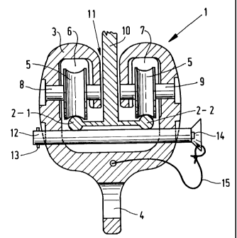
A fall protection system comprises substantially horizontal anchoring lines and at least one trolley capable of movement along the anchoring lines, which moves with an object to be secured, wherein the anchoring lines are arranged in parallel, spaced relation, and wherein the trolley is provided with multiple running gear which makes contact with each of said anchoring lines. Such a fall protection system is low--noise and low-vibration, and enables easy passage of the trolley along anchoring line supports, without this requiring extra effort and without this limiting the working space and the freedom of movement of the person secured to the fall protection system.


French Abstract

Un système de protection antichutes comprend des lignes d'ancrage sensiblement horizontales et au moins un chariot capable d'un mouvement le long des lignes d'ancrage, qui se déplace avec un objet devant être fixé, dans lequel les lignes d'ancrage sont disposées en parallèle, en relation espacée, et dans lequel le chariot est muni de multiples trains de roulement qui entrent en contact avec chacune desdites lignes d'ancrage. Un tel système de protection antichutes produit peu de bruit et de vibrations, et permet un passage aisé du chariot le long des supports de ligne d'ancrage, sans nécessiter d'effort supplémentaire et sans pour autant limiter l'espace de travail et la liberté de mouvement de la personne attachée au système de protection antichutes.

Claims

Note: Claims are shown in the official language in which they were submitted.


-6-


CLAIMS:


1. A fall protection system comprising:
substantially horizontal anchoring cables, wherein said
anchoring cables are arranged in parallel, spaced relation
to each other and each of said anchoring cables is
approximately round in cross-section and has an
approximately rounded outer contact surface;

at least one trolley for movement along said anchoring
cables together with an object to be protected from falling
by said fall protection system, said at least one trolley
including a multi-part running gear having at least two
rollers, wherein each roller of said at least two rollers
has an approximately rounded concave outer surface for
approximately matingly contacting said rounded outer contact
surface of each of said anchoring lines, thereby reducing
friction, and wherein said at least one trolley is
approximately U-shaped in cross-section so as to have first
and second arms extending from a base, said first and second
arms being fixedly attached to said base at a predetermined
distance from each other so that said first arm is non-
movable with respect to said second arm; and
a locking pin extending through said first and second
arms below said at least two rollers to prevent said
anchoring cables from becoming detached from said at least
one trolley, said locking pin being a quick-release type
locking pin having a spring-loaded release button;
wherein said running gear is of dual construction and
is movable over a pair of said anchoring cables, said dual
construction of said running gear including first and second
parts each having two rollers for engaging one of said
anchoring cables, a first roller of said two rollers being
arranged behind a second roller of said two rollers, which
first and second rollers run over a same anchoring cable of


-7-


said anchoring cables.

2. The fall protection system according to claim 1,
wherein a longitudinal axis of said locking pin is contained
in a transverse plane of said at least one trolley, said
transverse plane being perpendicular to a longitudinal axis
of each of said anchoring cables.

3. The fall protection system according to claim 2,
wherein said transverse plane extends between said first and
second rollers, which first roller is arranged behind said
second roller.

4. The fall protection system according to any one of
claims l to 3, wherein said spring loaded release button is
located at a first end of said locking pin and a cross pawl
is located at a second end of said locking pin so that said
cross pawl is retracted when said release button is
depressed in order for said locking pin to be removed from
said at least one trolley.

5. The fall protection system of claim 4, further
comprising a safety wire having first and second ends, said
first end of said safety wire being connected to said first
end of said locking pin and said second end of said safety
wire being connected to said at least one trolley for
preventing said locking pin from being separated too far
from said at least one trolley when said locking pin is
removed from a seated position within said at least one
trolley.

6. The fall protection system of claim 4, wherein when
said locking pin is removed from said at least one trolley,
said anchoring cables can be removed from said at least one


-8-


trolley through all interspace located between said at least
two rollers.

7. The fall protection system of claim 4, wherein when
said locking pin is seated in a position so as to be mostly
within said at least one trolley, said locking pin contacts
said anchoring cables.

8. The fall protection system of any one of claims 1 to 7,
wherein said anchoring cables are connected to each other by
a T-shaped support at spaced locations along a length of

said anchoring cables.

9. The fall protection system of claim 8, further
comprising an interspace in which a leg of said T-shaped
support extends through.

10. The fall protection system of any one of claims 1 to 9
further comprising an eye extending through said at least
one trolley, wherein said eye is for connecting the object
to be protected from falling by said fall protection system
to the trolley via a coupling means.

11. The fall protection system of any one of claims 1 to
10, wherein said at least one trolley includes a right-hand
part and a left-hand part which are mirror images of each
other so that said at least one trolley is symmetrical.

Description

Note: Descriptions are shown in the official language in which they were submitted.


CA 02291533 1999-12-03

FALL PROTECTION SYSTEM AND TROLLEY FOR USE IN SUCH A SYSTEM
The present invention relates to a fall protection system
comprising substantially horizontal anchoring lines and at
least one trolley capable of movement along the anchoring
lines, which moves with an object to be secured.
The present invention furthermore relates to a trolley for
use in such a fall protection system.
Fall protection systems are used when working at great
heights, for example on buildings, roofs, bridges and the like,
and they function to provide adequate protection against
falling.
EP-A-0 273 673 discloses a fall protection system of this
kind, which comprises a trolley which is slidable along an
anchoring line or cable, which trolley includes tubular
coupling means being rotatable round said anchoring line,
which coupling means is provided with a helical slot, in which
an intermediate fixture or support holding the anchoring line
engages. Said coupling means will rotate upon passing the
support, whereby part of the kinetic energy of the trolley is
converted into rotary motion of the tubular coupling means. The
coupling means then moves upwards over a thickening provided
round the anchoring line, which thickening engages in the slot,
thus holding the coupling means while passing the support. Then
the coupling means, which continues to rotate, moves downwards
on the other side of the thickening and slides further along
the anchoring line after having passed the support.
One drawback of the known anchoring line is the fact that
relatively much kinetic energy is lost, at the expense of an
unimpeded freedom of movement and work, upon passing the
support of the anchoring line, both to rotating the coupling
means - in particular when dirt has settled on the anchoring
lines, and to moving the trolley, first in upward direction and
then in downward direction, along the support provided with the
thickening.
The object of the present invention is to provide a safe,
low-noise protection system which provides unimpeded freedom to
work and an unobstructed manoeuvring space.
In order to accomplish that objective, the fall protection


CA 02291533 1999-12-03
- 2 -

system according to the invention is characterized in that the
anchoring lines are arranged in parallel, spaced relation, and
in that the trolley is provided with multipart running gear
which makes contact with each of said anchoring lines.
The advantage of the fall protection system according to
the invention is that the multipart construction of the running
gear of the trolley, which generally moves over two parallel
anchoring lines, makes it possible to pass an anchoring line
support running through the multipart trolley without any
obstruction, vibration or noise. The movement which the trolley
makes upon passing the support is a movement in a direction
exactly parallel to the al, without any objectionable vibration
or noise producing movement in transverse or vertical direction
of the trolley, and without such passing requiring extra effort
or attention from the person being protected by the fall
protection system. Another advantage of the fall protection
system according to the invention is that the extent of
protection and lasting reliability that is provided has been
enhanced, since falling objects cannot damage the multipart
construction of the anchoring lines so easily any more - in
particular near the supports - or cause them to kink. Moreover
it has become apparent that a certain degree of sag in the case
of heavier objects or loads, or in the case of larger free
spans between adjacent supports of the anchoring lines, will
less easily lead to an objectionable restriction of movement
for the present multipart system, since the multipart trolley
distributes the forces better and moves more smoothly over the
cables.
One embodiment of the fall protection system according to
the present invention is characterized in that the running gear
includes at least two rollers for the anchoring lines.
Advantageous is furthermore the fact that the rolling of the
running gear along the anchoring line requires comparatively
little energy and can take place in a low-friction manner,
whereby moreover the running gear will be impeded much less by
dirt which has settled on the anchoring lines.
Another embodiment of the fall protection system according


CA 02291533 1999-12-03
- 3 -

to the present invention is characterized in that the multipart
running gear is of dual construction and is movable over a pair
of anchoring lines. The advantage of this embodiment is the
symmetric and simple construction of the trolley, wherein
forces that occur will be distributed evenly over the two
anchoring lines.
Another embodiment of the fall protection system according
to the present invention is characterized in that the trolley
is provided with a locking device, which prevents the anchoring
line becoming detached from the trolley.
A very stable solution is provided by a fall protection
system according to the present invention, which is
characterized in that both the one part and the other part of
the dual running gear comprises two rollers for the anchoring
lines, one roller being arranged behind the other, which
rollers run over the same al.
The advantage of this embodiment is that when in practice
the fall protection system becomes active, the extent to which
the anchoring lines may be weakened of damaged will be minimal,
since the two-part running gear, each part comprising two
rollers, will distribute the forces that will occur in case of
a fall over the trolley and the anchoring lines, which
anchoring lines cannot kink in that case.
Yet another embodiment of the fall protection system
according to the present invention is characterized in that the
locking device extends through the transverse plane of the
trolley, so that the locking and releasing of the locking
device can take place in a simple manner, and so that it will
also be easy to connect the trolley to the anchoring lines or
disconnect it therefrom.
Further advantageous embodiments of the fall protection
system according to the invention and of the trolley for use in
said fall protection system are defined in the further
dependent claims.
The present invention and its further advantages will now
be discussed in more details with reference to the accompanying
drawing, wherein corresponding parts are indicated by the same


CA 02291533 1999-12-03
- 4 -

numerals in the various Figures. In the drawing:
Figure 1 shows a cross-sectional view of the fall
protection system according to the present invention; and
Figure 2 shows a front view of a trolley for use in the
fall protection system of Figure 1.

Figure 1 is a partial cross-sectional view of a fall
protection system 1 which is built up of anchoring lines,
cables, bands or rails 2-1 and 2-2 arranged in side-by-side,
parallel relation, over which a trolley 3 is movable in
longitudinal direction.
Figure 2 is a right-hand side view of trolley 3. The
anchoring lines 2-1 and 2-2 are generally provided horizontally
above an object to be secured, for example in the form of a
person. The object (not shown) is coupled to an eye 4 present
in the trolley by coupling means, which are for example known
from the field of industrial safety. The trolley 3 can move
along lines 2 by means of running gear mounted in trolley 3,
which is in this embodiment fitted with rollers 5 causing
little friction with anchoring lines 2, in that rollers 5 roll
over lines 2. In the illustrated embodiment, two rollers 5 are
arranged one behind another in each of the cavities 6 and 7 of
trolley 3. Rollers 5 are preferably made of a plastic, such as
nylon, or other material, such as for example a metal (bronze),
so that they can also be used in high-temperature environments,
such as in ovens. Rollers 5 are rotatable about shafts 8 and 9
in cavities 6 and 7. Seen in longitudinal direction, the
anchoring lines 2 are interconnected in regularly spaced
relation and secured to a structure (not shown) by means of
intermediate fixtures or supports 10. Figure 1 shows the
situation in which trolley 3 just passes support 10. As the
Figure shows, trolley 3 is of symmetric construction,
consisting of a left-hand and a right hand part, which parts
are separated by an interspace 11, through which a vertical
part of support 10 passes without impediment.
Trolley 3 is fitted with a locking device, which includes
a locking pin 12, which extends exactly through the transverse


CA 02291533 1999-12-03
- 5 -

plane between successive rollers 5 in the illustrated
embodiment, as is shown in particular in Figure 2. At the left-
hand end, seen in Figure 1, locking pin 12 is provided with a
cross pawl 13 which is movable in a direction transversely to
the longitudinal direction of locking pin 12, and which can be
retracted into locking pin 12 when a spring-loaded release
button 14 present on the right-hand end of locking pin 12 is
depressed.
Only after release button 14 has been depressed can
locking pin 12 be pulled out of trolley 3, by a double action,
as it were, and trolley 3 can be simply detached from anchoring
lines 2, if desired, by moving the separate anchoring lines 2-1
and 2-2 through the interspace. A safety wire 15 or chain
connected to locking pin 12 and secured to trolley 3 ensures
that locking pin 12 will remain near trolley 3 after being
pulled out, so that it can be inserted back in position again
after some time, in which position the trolley 3 cannot be
detached from anchoring lines 2. The locking pin 12, which can
also be passed through trolley 3 at another location, if
desired, is preferably made of hard steel, and trolley 3 is
preferably made of light metal.

Representative Drawing
A single figure which represents the drawing illustrating the invention.
Administrative Status

For a clearer understanding of the status of the application/patent presented on this page, the site Disclaimer , as well as the definitions for Patent , Administrative Status , Maintenance Fee  and Payment History  should be consulted.

Administrative Status

Title Date
Forecasted Issue Date 2008-08-05
(22) Filed 1999-12-03
(41) Open to Public Inspection 2000-06-07
Examination Requested 2004-11-29
(45) Issued 2008-08-05
Deemed Expired 2017-12-04

Abandonment History

There is no abandonment history.

Payment History

Fee Type Anniversary Year Due Date Amount Paid Paid Date
Application Fee $150.00 1999-12-03
Registration of a document - section 124 $100.00 2000-03-24
Maintenance Fee - Application - New Act 2 2001-12-03 $50.00 2001-09-26
Maintenance Fee - Application - New Act 3 2002-12-03 $50.00 2002-09-20
Maintenance Fee - Application - New Act 4 2003-12-03 $50.00 2003-10-06
Maintenance Fee - Application - New Act 5 2004-12-03 $100.00 2004-09-10
Request for Examination $400.00 2004-11-29
Maintenance Fee - Application - New Act 6 2005-12-05 $100.00 2005-09-16
Maintenance Fee - Application - New Act 7 2006-12-04 $100.00 2006-09-07
Maintenance Fee - Application - New Act 8 2007-12-03 $100.00 2007-11-29
Final Fee $150.00 2008-05-20
Maintenance Fee - Patent - New Act 9 2008-12-03 $100.00 2008-09-03
Maintenance Fee - Patent - New Act 10 2009-12-03 $125.00 2009-09-25
Maintenance Fee - Patent - New Act 11 2010-12-03 $125.00 2010-09-28
Maintenance Fee - Patent - New Act 12 2011-12-05 $125.00 2011-10-17
Maintenance Fee - Patent - New Act 13 2012-12-03 $125.00 2012-10-25
Maintenance Fee - Patent - New Act 14 2013-12-03 $125.00 2013-10-02
Maintenance Fee - Patent - New Act 15 2014-12-03 $225.00 2014-11-07
Maintenance Fee - Patent - New Act 16 2015-12-03 $225.00 2015-10-07
Owners on Record

Note: Records showing the ownership history in alphabetical order.

Current Owners on Record
ZIET VERDER BEHEER B.V.
Past Owners on Record
WESTERWEEL, JOZEF MARIA
Past Owners that do not appear in the "Owners on Record" listing will appear in other documentation within the application.
Documents

To view selected files, please enter reCAPTCHA code :


To view images, click a link in the Document Description column. To download the documents, select one or more checkboxes in the first column and then click the "Download Selected in PDF format (Zip Archive)" or the "Download Selected as Single PDF" button.

List of published and non-published patent-specific documents on the CPD .

If you have any difficulty accessing content, you can call the Client Service Centre at 1-866-997-1936 or send them an e-mail at CIPO Client Service Centre.


Document
Description 
Date
(yyyy-mm-dd) 
Number of pages   Size of Image (KB) 
Drawings 1999-12-03 1 23
Representative Drawing 2000-05-29 1 10
Abstract 1999-12-03 1 21
Description 1999-12-03 5 258
Claims 1999-12-03 2 64
Cover Page 2000-05-29 1 37
Claims 2007-08-14 3 115
Representative Drawing 2008-07-21 1 14
Cover Page 2008-07-21 2 47
Fees 2004-09-10 1 27
Correspondence 2000-01-07 1 2
Assignment 1999-12-03 3 82
Assignment 2000-03-24 3 108
Fees 2003-10-06 1 34
Fees 2001-09-26 1 35
Fees 2002-09-20 1 33
Prosecution-Amendment 2004-11-29 1 24
Fees 2005-09-16 1 26
Fees 2006-09-07 1 29
Prosecution-Amendment 2007-02-14 3 105
Prosecution-Amendment 2007-08-14 5 154
Fees 2007-11-29 1 31
Correspondence 2007-11-28 1 25
Correspondence 2008-05-20 1 38
Fees 2008-09-03 1 35
Fees 2009-09-25 1 35
Fees 2010-09-28 1 37