Note: Descriptions are shown in the official language in which they were submitted.
CA 02291643 1999-11-30
WO 98/56514 PCTNS98/117?1
IMPROVED METHOD OF MELTING SOLID MATERIALS
TECHNICAL FIELD
This invention relates to the melting of solid materials to produce a
vitrified and/or crystalline material, by initiating a melt by passing
electrical current
through a planar starter path positioned between a plurality of electrodes,
and thence
through the surrounding solid materials. The solid materials may be soil,
either
undisturbed or staged, waste materials assembled at a site for disposal, or
any other
solid materials that can be melted and which will support joule heating during
processing.
BACKGROUND OF THE INVENTION:
ln-situ vitrification or melting of soil and other solid materials is well
known, as illustrated by the many patents issued to, among others, Battelle
Memorial
Institute. For example, U.S. Patent No. 4,376,598 issued March 15, 1983,
discloses a method of solidification of soil and other solid materials
contained in the
soil, by passing electrical current through melted materials between
electrodes. An
initial electrically conductive resistance path is provided between the
electrodes, and
application of current to the electrodes is continued until the solid
materials between
the electrodes have been melted.
The electrically conductive resistance path (the "starter path") is
necessary to obtain electrical conduction between the electrodes sufficient to
initially
generate adeduate heat to melt the soil and other solid materials adjacent to
the
starter path, and then to transfer the flow of current to these melted
materials. Upon
melting, the molten earth or other material becomes significantly more
electrically
conductive than it is in the unmelted state. Electricity then can flow through
the
molten media, being converted to heat by the phenomenon of joule heating,
which
heat is then conducted into and melts more adjacent solid materials. Such
melting
has heretofore been initiated at or near the upper surface of the solid
materials in a
horizontal linear path, with the melt area growing outward and downward as
electrical power continues to be applied.
A number of different methods of establishing the electrically conductive
resistance path have been proposed, such as graphite or sodium hydroxide
paths,
sacrificial resistance elements (a metal resistance coil or wire), and
chemical reagents
1
CA 02291643 1999-11-30
WO 98/56514 PCT/US98/11771
to create a highly exothermic chemical reaction. In U.S. Patent No. 5,004,373,
a
cord of dielectric material (such as glass fiber) is impregnated with a
conductive
material (such as graphite) for initiating in-situ vitrification.
As illustrated in U.S. Patent No. 4,376,598, the starter path was a
relatively small "layer" (2.5 cm deep and 2.5 cm in width) of graphite flakes
in a
trench between the electrodes. The intent of such graphite layer was merely to
"provide a conductive resistance path [between the electrodes toJ raise the
temperature of the soil about the conductive resistance path to its melting
temperature. " While it was contemplated that the vitrification of materials
would
proceed as illustrated in the ' 598 patent, in fact it was found that the
formation of the
melt zone more closely approached that illustrated in U.S. Patent No.
4,956,535.
Starter paths having graphite as a primary component (generally in the form of
flakes) are now the preferred method of initiating the melting process.
It is now known that with a horizontal, linear starter path placed near the
surface of the ground as in the prior art, the melt zone progresses as
illustrated in Fig
1 herein ("Prior Art") and in Fig. 10 and 12 of the '535 patent. As
illustrated in
Fig. 1, the melt 10 is initiated by a horizontal linear starter path 26 and
assumes a
balloon configuration, as it expands in all of the "X" (laterally in the plane
between
the electrodes), "Y" (downwardly"), and "Z" (laterally perpendicular to the
plane of
the electrodes) dimensions. The result is a melted cylindrical mass with
hemispherical ends. The melt pool 10 illustrated herein represents the
"growth" of
the melted area as the melt pool grows. Therefore, as illustrated in Fig. 1
(and in
subsequent drawings) , the melt pool grows sequentially from the startup at A,
and
then grows downwardly and outwardly to B, C, D and E. The previous melt pools
(A - D) are shown as discrete entities for the purposes of illustration only --
in fact,
the melt pool increases in size over time until it results in a single large
melted area.
Volume reduction and subsidence accounts for the location of the final melt
pool
and solidified mass occupying a volume substantially smaller than that
previously
occupied by the unmelted solid materials (the volume of A+B+C+D+E). As
illustrated in the '535 patent, additional electrodes were necessary to
"square up" the
vitrified mass. Through experience, it has been found that conduction of heat
from
the melted volume into adjacent unmelted materials is directly related to the
melted
2
CA 02291643 1999-11-30
WO 98!56514 PCT/US98/11771
volume's surface area.
In theory, in perfectly dry, uniform soil, a melt will progress uniformly
in all of the X, Y and Z directions. Because the melt progresses in both
directions
(from a line drawn between the electrodes) in the "Z" dimension, the lateral
growth
will theoretically be twice the downward growth, hence a theoretical aspect
ratio (the
ratio of depth-to-width: Y/Z) of 0.5. It is believed, however, that because
most
materials to be melted contain liquids or other vaporizable materials (such as
water
in soil) which will be vaporized by the downwardly-encroaching melt pool, the
relatively "cool" vapors will proceed up the sides of the melt pool, cooling
the sides
and slowing the rate of lateral (Z) growth. Therefore, the rate of downward
growth
of a prior art melt pool will increase nominally faster than the lateral
growth rate,
resulting in an actual aspect ratio of up to 1.5. However, as the melt pool
grows
larger, other factors related to heat transfer cause the rate of downward
("Y")
melting relative to outward ("Z") melting to diminish (illustrated in Fig. 1
with
successive melts A, B, C, D and E), and ultimately it becomes uneconomic to
continue melting with the intent of extending the melt downward with
conventional
equipment, since the rate of (unwanted) growth in the "Z." dimension greatly
exceeds
the rate of desired growth in the "Y" dimension. Thus, the conventional
technology
is limited to operation with melt aspect ratios in the range of approximately
1.0 to
1.5.
Applicant has observed in large scale applications employing up to four
megawatts of power, and utilizing the prior art linear starter path startup
procedure.
after a 4-electrode melt reaches about 20' (6.1 m) in depth, with a width of
approximately 40-45' (12-13.7 rn), the downward growth of the melt slows to a
point of being uneconomic to continue (insufficient power is available to melt
a
much larger mass) > and such melts are typically terminated at that point, or
earlier.
Therefore, when using commercially available large scale equipment, there is
an
inherent limit to how deep one can extend in situ vitrification. Of course,
more
powerful equipment can be used to produce even larger, deeper melts; however
such
equipment would have its own economic depth limit.
Applicant has found that, in using the methods disclosed in, for example, the
'598 patent, the current pracaicaI limit of melt depth ("Y") using commercial
scale in-situ
3
' ~ CA 02291643 2005-02-18
vitrification equipment (4 MW) is approximately 20 feet (6.1 m). At this
depth, using a
starter path as disclosed in the '598 patent, the melt width ("Z") is
approximately 20-22
feet (6.106.7 m) per pair of electrodes, or about 45 feet (13.7 m) for 4
electrodes.
Therefore, unless the area to be vitrified is at or above about 20 feet (6.1
m) below the
surface, it is not economical to continue melting laterally in order to
minimally increase
the depth of the melt. While thermal barriers may be employed to limit lateral
("Z")
melt expansion, such barriers are difficult to construct, may not work
properly, and are
expensive.
As noted above, conventional melts having a horizontal Linear starter path
necessarily begin very wide and very shallow, thereby producing a very low
aspect ratio
(depth/width), which increases as the melt grows in depth. Applicant has
observed that
the aspect ratio of conventional melts rarely if ever is greater than about
1.0, or 1.3 at the
maximum, at depths of commercial interest. For example, using conventional
equipment, the largest practicable melt at the closest electrode separation of
approximately 10 feet (3 m) with a horizontal linear starter path
therebetween, produces a
melt approximately 20' (6.1 m) wide and 20' (6.1 m) deep per pair of
electrodes.
There are many cases in which a shaped melt zone (having an aspect ratio of
> 1.5) may be desirable. The ISV process of the '535 patent produces a melt
that
"grows" at will, whereas the present invention permits a melt to be tailored
to fit either
the site requirements and/or to reduce cost. One of the greatest advantages of
being able
to control melt aspect ratio is the minimization of widthwise overmelting.
For example, when it is desired to melt a volume 20 feet (6.1 m) deep and
10 feet (3 m) wide using conventional technology, it would be necessary to
melt 20' (6.1
m) wide in order to attain the 20' (6.1 m) depth. Such processing involves
melting twice
the amount of material targeted, resulting in twice the time and cost. In such
applications, it is desirable to perform a melt with an aspect ratio of 2.0
(twice the depth
as width). The ability to control the aspect ratio can have tremendous impact
on the cost
of a melt and therefore its commercial viability.
As illustrated in Fig. 2, many hazardous waste sites are arranged as trenches
12 wherein the hazardous waste is buried with soil in a "U" or "V" shaped
trench. The
side walls of the trench may be lined with rock 14. In-situ vitrification may
not be cost
effective, or may present safety problems, in such cases since the natural
formation of the
4
CA 02291643 1999-11-30
WO 98/56514 PCTNS98/11771
balloon shaped melt pool 16 (as illustrated in the ' 535 patent) is the exact
opposite shape
one would desire in such cases. Because the melt may seal off to the sides of
the trench,
lateral movement of gases 18 generated under the melt pool 16 may be
restricted by the
sides of the trench, and such gases may be forced upwardly 20 through the melt
zone 16,
creating disturbances and discontinuities therein. Such "bubbles" may cause
significant
problems in maintaining an effective melt and may cause eruptions at the
surface,
endangering the integrity of electrodes 22 and off-gas collection apparatus 24
covering
the melt. Such eruptions have been severe enough to cause melting and/or
damage to
hood components 24 and other equipment associated with the ISV process.
Generally speaking, in-situ vitrification now proceeds with electrodes 28 that
are continuously fed (possibly through a sleeve 30) into the melt pool as the
melt process
proceeds (Fig. 3). As currently practiced, neither the electrodes nor the
sleeves are
initially inserted to the desired final depth during startup. As the melt pool
grows
downwardly, the electrodes are fed dawnwardly.
Additionally, there have been many attempts to create subterranean "walls"
of vitrified material to act as barriers. Such underground structures have not
heretofore
been constructed economically or with precision, because the aspect ratio is
so small
{melts are too wide) as to make such structures uneconomic. Accordingly, a 20'
{6.1 m)
deep wall made by two electrodes using conventional methods produces a 20'
(6.1 m)
wide (or wider) melt -- using substantially more time and energy melting than
is required
to produce a "wall. " For barrier wall applications, it is desirable to be
able to control
melt aspect ratio in the range of 4 to 20, which is impossible when using
prior art
technology (capable of maximum aspect ratios in the range of 1.0 to 1. 5) .
Numerous inventions have been disclosed to aid in the practice of in-situ
vitrification. For example, U.S. Patent No. 4,762,991 discloses a probe which
monitors a plurality of sensors placed along the expected path of an ISV melt.
The probe
receives temperature signals from the sensors and transmits them to a remote
location.
U.S. Patent No. 5,024,556 discloses a system to promote destruction of
volatile and/or
hazardous contaminants during in-situ vitrification by forming a cold cap over
the
vitrified mass.
5
CA 02291643 1999-11-30
WO 98/56514 PCTNS98/11771
DISCLOSURE OF INVENTION:
The present invention comprises a method, and an apparatus to practice the
method, of melting solid materials wherein a more precisely sized and shaped
melt pool,
and subsequent cooled monolithic glass and/or crystalline mass, may be
obtained. Such
control of the melt may be required because of physical site limitations, or
to effectively
vitrify a relatively small section of an underground location, or to construct
a
subterranean "wall. "
The method of the present invention comprises conventional in situ
vitrification processing equipment, with at least two electrodes that extend
initially
downwardly through the ground to a depth sufficient to produce the desired
melt zone.
Electrically conductive resistance materials are placed between the electrodes
for a
substantial portion of their linear dimension to form a starter path, thereby
defining a
vertically-oriented plane of starter path material between the electrodes.
When electricity
is applied to the electrodes, the electrically conductive resistance materials
are heated to a
temperature greater than the melting point of the surrounding soil or other
solid material.
Upon melting, the melted soil then conducts electricity more easily, and
continued
resistance heating of the melt causes adjacent soil to form a growing "melt
pool" of
melted materials.
The method of the present invention can be practiced on any material capable
of being melted by joule heating, and in particular on contaminated
undisturbed soil, on
soil moved to a location for processing, on a mixture of "in situ" soil and
solid materials
(suc:h as drums or other waste products) , or in any other configuration
wherein it is
desired to melt solid materials.
The aspect ratio of the melt pool of the present invention can be controlled
with relative precision, such that the ratio of the vertical dimension ("Y")
of the melt
pool formed by the method of the present invention to the width dimension
("Z") may be
controlled in the range of about 1 to 20, indicating that the melt pool can be
created and
controlled downwardly without significant undesired lateral growth of the
melt~pool.
The present invention also comprises an apparatus in the form of at least two
vertically oriented linear electrodes and a planar starter path in contact
with the electrodes
over a substantial portion of the linear dimension of the electrodes. This
apparatus
assures that the melt pool starts deeper, with an initial aspect ratio of
about 40-50, so that
6
CA 02291643 1999-11-30
WO 98/56514 PCT/US98/11771
the desired depth of the melt pool is not limited by unwanted and uneconomical
lateral
growth.
Other aspects of the present invention will become apparent with reference to
the following description of the various embodiments the invention may take.
BRIEF DESCRIPTION OF DRAWINGS:
FIG. 1 is a schematic representation of a melt pool created by conventional
in-situ vitrification and labeled "Prior Art" ;
FIG. la is a representation of the dimensions of a melt pool;
FIG. 2 is a schematic representation of a specific type of melt application
and
labeled "Prior Art" ;
FIG. 3 is a schematic representation of the electrodes and linear starter path
of a conventional in-situ vitrification process, labeled "Prior Art" ;
FIG. 3A is a sectional view of the starter path of FIG. 3 taken along lines
3A-3A of FIG. 3;
FIG. 4 is a schematic representation of the electrodes and planar starter path
of the process of the present invention;
FIG. 4A is a sectional view of the starter path of FIG. 4 taken along lines
4A-4A of FIG. 4;
FIG. 5a is a schematic representation of a side view of a melt pool
configuration of the prior art, wherein adjacent lines illustrate growth of
the melt pool;
FIG. 5b is a schematic representation of a side view of a melt pool
configuration of the present invention similar to that of FIG. 5a;
FIG. 6 is a schematic representation of a plan view of a melt pool
configuration of the present invention;
FIG. 7 is a plan view of a 4 electrode set comparing the instant invention to
the prior art;
FIG. 8 is a schematic representation of an elevation view of the experimental
apparatus of Example 1;
FIG. 9 is a representation of a plan view of the solidified melt pool produced
by the method of the present invention in Example 2;
FIG. 10 is a schematic representation of the use of the present invention in
the same environment as illustrated in FIG. 2;
7
CA 02291643 1999-11-30
WO 98/56514 PCT/US98/11771
FIG. lla is a schematic representation of an elevation view of a multiple
electrode set of the method of the present invention;
FIG, llb is a schematic representation of a plan view of the embodiment of
FIG. l la;
FIG. 12 is a schematic representation of a plan view of a further embodiment
of the present invention;
FIG. 13 is a schematic representation of an elevation view of a still further
embodiment of the present invention;
FIG. 14a is a schematic representation of a specific type of melt labeled
"Prior Art" , ;
FIG. 14b is a schematic representation of the method of the present invention
in the environment of FIG. 14a, and
FIG. 15 is a graph illustrating a comparison between the instant invention
and the prior art.
BEST MODE FOR CARRYING OUT THE INVENTION:
As used herein, the following terms have the following definitions:
IN-SITU VITRIFICATION (ISV) : means vitrification or melting of
materials as they lie at the time of treatment. Such materials may be
undisturbed
from their locus of deposition or origin, or they may be excavated and moved
(staged) to a different location for treatment. Whereas the term
"vitrification" is
often thought of as the making of a glass product, the use of this term by
those
skilled in this art may also include processes wherein materials are melted
but not
glassified, instead making a solidified glass and/or crystalline amorphous
mass.
SOLID MATERIAL: means earthen materials capable of being melted
by joule heating, including soil, soil contaminated with liquid hazardous or
other
wastes, or a mixture of soil and solid hazardous wastes as typically found at
hazardous waste disposal sites, sediments, mine tailings and other
predominantly
inorganic materials.
HAZARDOUS WASTES: means wastes requiring treatment, however
classified, including those wastes defined by those in the industry as
hazardous,
radioactive and mixed wastes.
8
CA 02291643 1999-11-30
WO 98/56514 PCT/US98/11771
STARTER PATH: means an electrically conductive resistance material
placed between at least two electrodes to initiate melting of solid material.
While in
many cases conventional materials such as graphite flakes, or graphite flakes
mixed
with glass frit is the preferred embodiment, it is to be appreciated that any
material
having the desired electrical resistance characteristics (such as, in some
cases, native
soil) may be utilized.
As should be apparent from the definitions above, it is intended that the
definition of in-situ vitrification (ISV) not be limited to the situation
wherein a
relatively undisturbed site is contaminated with, for example, a hazardous
chemical
spill. Sites having buried wastes, sites where the contaminated soil or other
solid
material has been excavated and removed to a secondary site for processing,
and the
like are also to be included within this definition. For ease of description,
hereinafter whenever the term "ground" is used, it is to be understood that it
comprises any embodiment wherein solid material is subjected to in-situ
vitrification.
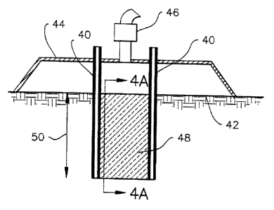
As illustrated in Fig. 4, the broadest embodiment of the present invention
involves at least two linear electrodes 40 (either sheathed or unsheathed)
inserted into
and beneath the surface of the ground 42. It is to be appreciated that while
the
method of the present invention is illustrated in the context of vertically-
oriented
electrodes and starter path, other geometries are possible (such as electrodes
inserted
into the soil at an acute angle to the surface of the soil) . It is also to be
understood
that the upper dimension of the planar starter path need not be at grade level
-- the
starter path may begin a predetermined distance below grade and proceed
downwardly therefrom.
A containment hood 44 and off-gas treatment apparatus 46 are shown
schematically herein; these are well-known to those of ordinary skill in this
art and
require no further description. In contrast to the prior art methods, wherein
the
electrodes are inserted minimally into the ground and then fed into the melt
as it
progresses {Fig. 3), the electrodes 40 of the present invention are inserted a
substantial distance into the ground, generally to the full depth of the
planar starter
path. Between the electrodes, electrically conductive resistance materials 48
(the
starter path) are placed. When in place, the starter path will assume a planar
configuration and will traverse a significant portion of the linear dimension
("Y") of
9
CA 02291643 2004-11-09
the electrodes. As used herein, "planar" need not be flat -- that is, the
planar starter
path may be provided with a curvature or other irregular shape between the
electrodes. The greater total area of starter path allows for passage of
significantly
more electrical power to be delivered during operation than with conventional
linear
5 starter paths, as is evident from a comparison of Figs. 3 and 4. The linear
(vertical)
dimension 50 ("Y" of Fig. la) of the starter path 48 will determine the
dimensions of
the final melt pool.
In contrast to the melt pool of Fig. 1 of the prior art, the melt pool of the
present invention is illustrated schematically in Figs. Sa and Sb. (Note that
the orientation of
the electrodes of Figs. Sa and Sb are 90 degrees from that of Fig. 1; that is,
Fig. 1 is a view
along the "Z" axis whereas Figs. Sa and Sb are a view along the "X" axis.)
Whereas the prior
art melt pools generally have an aspect ratio (the ratio of depth:width) less
than 1.0,
the melt pools of the present invention have aspect ratios generally in the
range of
1.0 to 20. With a starter path dimension of "Y" °in Fig. Sb, the depth
dimension will
15 always exceed "Y" (there will be some growth downwardly from the
electrodes) ;
while the width dimension "Z" 52 can be controlled to be substantially
smaller.
Because melting will always first occur adjacent the starter path, the "Y"
dimension
of the melt pool will typically correlate with the vertical dimension of the
starter
path. When cooled, the melt pool will comprise a crystalline and/or glass
monolith
20 approximating the size and shape of the final melt pool. The "X" (width)
dimension
54 of Fig. 6 of the melt pool will typically be somewhat larger than the
dimension
between the two electrodes. While some growth in the "X" dimension beyond the
electrode separation dimension may be expected, such growth can be anticipated
so
as to not impact the economics of the present invention.
25 Fig. 7 illustrates the ability of the present invention to design a melt
shape to more accurately and cost-effectively remediate a site. In the event
that a
site designated for remediation comprised a generally rectangular or square
configuration (represented by the outline 56) , conventional prior art
technology
would require a 4-electrode (57a, b, c, d) set and would create a generally
circular
30 melt pool 58. With the present invention, however, a similar 4 electrode
set will
create two distinct melt pools (59, 61) which fuse into a roughly rectangular
shape
63. As is evident from the plan view of Fig. 7, the melt pool 63 of the
instant
CA 02291643 1999-11-30
WO 98/56514 PCT/US98/11771
invention saves the melting of the additional material (as at 65) , thereby
increasing
the cost effectiveness of the process.
The starter path material of the present invention is preferably comprised
of a combination of graphite flakes and glass frit. However, as will be
evident to
those skilled in this art, any electrically conductive material with the
desired level of
resistance for the melt size desired may be used as starter path material. As
set forth
in greater detail below, applicant has found that in a particular application,
a starter
path mixture may comprise approximately 50% graphite flakes and 50% glass
frit,
and in such case will provide optimum resistance for melting of surrounding
soil. It
is anticipated that the optimum starter path material and composition will
vary with
each different application of the invention -- the design will provide the
desired
resistance to electrical flow for heating purposes to provide the desired melt
geometry.
The electrodes, and thus the starter path, is most often oriented vertically
within the solid material to be treated. F'or relatively narrow {Z direction)
melts the
electrodes and the starter path can be positioned from the outset to near the
full
target depth, thereby enabling melting of surrounding solid materials at full
depth
almost immediately after initiation of the process. Because of the full depth
initiation, the "X" and "Z" dimensions at the lowermost portions of the melt
pool
will be much smaller than with conventional top-down melting where the melt
pool
grows laterally as it progresses downwardly to the target depth.
The improved starter path of the present invention presents a number of
advantages over the conventional ISV operation. Assuming a target depth
greater
than a couple of feet (0.6 m) , for example about 20 feet (6.1 m) , the
present
invention completes melting much more quickly and efficiently than
conventional
ISV. Conventional ISV must "ramp-up" to full power, since as the melt grows in
size, greater current is applied to the expanding melt pool . The present
invention -
allows full power operation much more quickly, thus increasing the average
melt
power level and reducing overall melt cycle time by 10-20%.
Applicant has also found that performance of planar starter path melts is
more energy efficient than those of prior art melt designs. The improved
energy
efficiency results from less heat being lost to the ground surface with the
high aspect
11
CA 02291643 1999-11-30
WO 98/56514 PCT/US98/11771
ratio of the present invention than is experienced with low aspect ratios of
the prior
art (the melt pool doesn't grow as large laterally). This further adds to the
cost
effectiveness of the instant invention.
Melt shape control will be enhanced in most vitrification or melting
applications where maximum melt pool width ("Z") is not desired. Of perhaps
greatest benefit is the potential for substantial reduction in operating
costs: because
the melt can be more targeted and localized, less "over melting" will occur
and
savings in time and energy, coupled with faster turnover of equipment, can
reduce
overall costs from 25-50% when compared to the prior art.
The significance of the present invention will be more apparent with
reference to the following example.
EXAMPLE 1
A large scale ISV test was conducted to determine the feasibility of the
present invention in an actual in-situ environment. At a site outside Spokane,
WA,
Applicant prepared a relatively undisturbed site using Applicant's commercial
scale
in-situ vitrification equipment. Conventional 12-inch (30 cm) diameter solid
graphite electrodes were used. After excavation, sonnotubes with electrodes
therein
(packed with a mixture of 1 part glass frit to 2 parts graphite flakes) were
placed 15'
(4.6 m) apart. The ptanar starter path was constructed by stacking a plurality
of 3"
{7.6 cm) , diameter tubes one on top of the other between the electrodes. 16
tubes
were stacked to form a starter path 4' (1.2 m) in height and 3" (7.6 cm) in
thickness,
and soil was back-filled as the tubes were stacked on top of one another. Each
starter tube was filled with 3 parts glass frit to 2 parts graphite flakes.
As was consistent with other startups using the instant invention,
Applicant observed that the electrical performance of the startup in this
Example was
unusually smooth, whereas prior art startups involved more erratic variations
of
electrical parameters that have to be carefully manually controlled during
startup.
The test lasted for a period of about 24 hours, during which a planar wall-
shaped
melt was produced to a depth of 5' (1.5 m) and a width averaging 2' (.6 m) (an
aspect ratio of about 2.5) . The vitrified volume exhibited nearly vertical
side walls.
The power utilization efficiency was 1 kWh/ton (1.1 kWh/t) of cooled mass. It
is
Applicant's experience that a conventional melt would have required several
days to
12
CA 02291643 1999-11-30
WO 98/56514 PCT/US98111771
reach the 5' (1.5 m) depth, and would have produced an excessively wide melt
between approximately 4' (1.2 m) and 5' (1.5 m) at considerably lower energy
efficiencies.
kWh/t Aspect Ratio Shape of Sides
Example 1 1.1 2.5 Vertical
Prior Art > 1.1 1.0-1.5 Rounded
RESULTS: After power was shut off and the solidified mass 70 (Fig. 9)
allowed to cool, dimensions of the mass were measured. The total "X" dimension
74 was approximately 15' (4.6 m) -- the distance between the electrodes 72. No
growth was noted beyond the electrodes in the "X" dimension. The height ("Y"
dimension) of the mass varied from 55" (138 cm) to 58" (147 cm), and the width
of
the melt ("Z" dimension) 76 was from 16" (41 cm) to 30" (76 cm). No effort was
made to optimize the energy efficiency in this test.
DISCUSSION: it is apparent that the method of the present invention
offers great latitude in designing ISV patterns to treat solid materials in a
number of
dimensional scenarios heretofore unavailable. The instant invention permits
melts to
be designed and conducted at much reduced cost, and with increased safety. For
example, in treating wastes buried in trenches as set forth in Fig. 2, the
method of
the present invention will permit vapors to be "flushed" out the sides of the
melt pool
without disruption of the pool as previously experienced. As illustrated in
Fig. 10,
the vapors 80 from liquid 82 may escape the bottom of the melt pool 84 within
trench 86. Because the aspect ratio of the melt pool is substantially greater
than that
of a conventional ISV process, the melt pool does not span the trench from
side to
side before it reaches the bottom of the trench -- especially valuable where
rock side
walls may be present. It is anticipated that when optimized, the energy
efficiency of
melts made according to the present invention will have an energy efficiency
of 0.7,
or less.
A massive monolith may be constructed by initiating successive melts
side-by-side (Fig. 11). In this embodiment, successive electrode sets 90, 92,
94
may be made, with the respective melt pools 96, 98, 100 fusing together to
form a
relatively cubic block 102, without the "balloon" shape, and the associated
13
CA 02291643 1999-11-30
WO 98/56514 PCT/US98/11771
unintended vitrification of adjacent uncontaminated soil, associated with the
prior
art. Alternatively, relatively thin walls (Fig. 12) may be constructed by
arranging
the sequential electrode sets 104, 106, 108 end-to-end to create adjacent
individual
walls 110, 112, 114 which fuse together. Such walls may be constructed as
straight,
segmented (generally curved), or arranged into enclosed shapes to be used for,
among other things, underground barriers to prevent migration of pollutants,
or as a
"vault" around a discrete area of pollutants to essentially contain the
impacted area.
Still other shapes may be constructed by the method of the present
invention. For example, as illustrated in Fig. 13, multiple planar starter
paths may
be arranged one on top of the other to create a vertical wall from a plurality
of
hardened melt pools 116, 118, 120. Such design may be used when ;r ;~
impracticable or inconvenient to construct the wall in a single melt, when the
desired
depth exceeds the practical limitations for melting depth of the present
invention, or
if limited by the available equipment power level. Single or multiple
electrode sets
may be used for such an embodiment.
Subterranean strata may be encountered wherein a discrete, highly
contaminated organic layer 130 is disposed in a horizontal configuration, as
illustrated graphically in Fig. 14a. When a conventional melt pool 132 with a
low
aspect ratio and broad lower boundary 134 contacts the Layer, a large amount
of the
organic material is rapidly vaporized (at 136) , possibly overwhelming the
ability of
the off-gas treatment system 46 to treat the released gases. Additionally, the
long
pathway for vapors to traverse the bottom of the melt 132 increases the
likelihood
that a portion of the vapor will pass upwardly through the melt, causing the
problems
noted above. Conversely, the melt pool 138 of the present invention (arranged
in
Fig. 14b at a right angle to the orientation of Fig. 14a) attacks the organic
layer
130 with a relatively small lower boundary 140, and once through the layer,
the side
boundaries 142 of the melt pool are likewise small enough to produce a
manageable
amount of the vaporized organic material 144.
Fig. 15 graphically illustrates the mathematical relationship between the
aspect ratio (depth/width} and depth and width individually, and provides a
method
of identifying the depth of planar starter path needed to produce a melt of
the desired
depth and aspect ratio. With the aspect ratio plotted on the ordinate, and
depth
14
CA 02291643 1999-11-30
WO 98/56514 PCT/US98/11771
plotted on the abscissa, the width of melt that satisfies those conditions can
be
plotted, as indicated by the 2' , 5' , 10' and 15' (.7 m, 1.5 m, 3 m, 4.6 m)
melt width
lines originating at the origin. Similar lines for any desired melt width can
be
plotted. To understand the use of the plotted melt width lines, consider for
example
that a 10' (3 m) wide melt at a depth of 30' (9 m) requires an aspect ratio of
3.
Similarly, a 10' {3 m) deep melt that is 5' (1.5 m) wide requires an aspect
ratio of 2.
While the chart of Fig. 15 can be used by engineers to specify the aspect
ratio required for a particular melt, it is necessary to couple this
information with the
inherent growth characteristics of melts in the media being treated in order
to
determine the depth of planar starter path to be employed for a particular
melt. This
coupling is indicated by the curved lines on the chart which are
representative of 8'
(2.4 m) and 12' (3.6 m) deep planar starter path melts in typical silica based
soil --
the 8' (2.4 m) and 12' (3.6 m) lines represent the starting depth of the
planar starter
path. Similar lines can be constructed for starter paths of different depths.
ILLUSTRATIVE EXAMPLE 1. if a 10' (3 m) deep melt with an aspect
ratio of 2 (e.g. 5' (1.5 m) wide) is desired, an engineer would employ a
planar melt
that used an 8' (2.4 m) deep planar starter path. Such a planar melt would
start 8'
(2.4 m) deep with a very high aspect ratio, and would grow to a width of 5'
{1.5 m)
by the time it melted to a depth of 10' (3 m), thus attaining the desired
depth and
aspect ratio objectives.
ILLUSTRATIVE EXAMPLE II. If a melt 15' ( 4.5 m) deep and 7' (2.1
m) wide is desired, it could not be accomplished with an 8' (2.4 m) deep
planar
starter path, but could be achieved by employing a 12' (3.6 m) deep planar
starter
path. The 12' deep starter path would produce a melt with a very high aspect
ratio
initially, and would widen to 7' (2.1 m) by the time it melted to a depth of
15' (4.6
m) , reaching the target dimensions with an aspect ratio of about 2.1.
ILLUSTRATIVE EXAMPLE III. If a wall-like melt 10' (3 m) deep and
2' (0.6 m) wide is desired, a 9' {2.7 m) deep starter plane can be used. By
the time
the melt grows to a depth of 10' (2 m) the melt will have grown to a width of
about
2' (0. 6 m) .
It is apparent that the planar starter paths can produce melts substantially
below their original starting point, however at the cost of the aspect ratio
and melt
CA 02291643 1999-11-30
WO 98/56514 PCT/US98/11771
efficiency. For example, in the ILLUSTRATIVE EXAMPLE II above, an 8' (2.4
m) deep starter path could be utilized for a 15' (4.6 m) deep melt, however
the
aspect ratio will be only about 1.3. If a higher aspect ratio is desired, a
deeper
starter path is required. The method of the present invention PnahIP~
Annlirant tn
mathematically model these relationships based on actual melting
characteristics of
various media to be treated.
While a number of embodiments of the present invention have been
shown and described herein, it will be apparent to those skilled in this art
that many
other changes and modifications may be made to the inventions disclosed,
without
departing from the invention in its broadest aspects. Accordingly, the scope
of this
invention should be determined solely by the scope of the claims appended
hereto,
which are intended to cover alt such changes and modifications that fall
within the
scope of the invention.
16