Language selection

Search

Patent 2291707 Summary

Third-party information liability

Some of the information on this Web page has been provided by external sources. The Government of Canada is not responsible for the accuracy, reliability or currency of the information supplied by external sources. Users wishing to rely upon this information should consult directly with the source of the information. Content provided by external sources is not subject to official languages, privacy and accessibility requirements.

Claims and Abstract availability

Any discrepancies in the text and image of the Claims and Abstract are due to differing posting times. Text of the Claims and Abstract are posted:

  • At the time the application is open to public inspection;
  • At the time of issue of the patent (grant).
(12) Patent: (11) CA 2291707
(54) English Title: A CLAMPING SPRING RING
(54) French Title: BAGUE ELASTIQUE DE FIXATION
Status: Expired
Bibliographic Data
(51) International Patent Classification (IPC):
  • F16B 21/18 (2006.01)
  • H02K 5/15 (2006.01)
  • H02K 5/173 (2006.01)
  • H02K 5/22 (2006.01)
(72) Inventors :
  • BRATTHALL, JOHAN (Sweden)
  • STAHL, BORJE (Sweden)
  • OGREN, LARS (Sweden)
(73) Owners :
  • ITT MANUFACTURING ENTERPRISES, INC. (United States of America)
(71) Applicants :
  • ITT MANUFACTURING ENTERPRISES, INC. (United States of America)
(74) Agent: SMART & BIGGAR LLP
(74) Associate agent:
(45) Issued: 2003-06-10
(22) Filed Date: 1999-12-03
(41) Open to Public Inspection: 2001-06-03
Examination requested: 1999-12-03
Availability of licence: N/A
(25) Language of filing: English

Patent Cooperation Treaty (PCT): No

(30) Application Priority Data: None

Abstracts

English Abstract

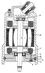
The invention concerns a device for mutual locking of two concentric cylindrical parts such as parts to be used in a submergible pump unit. One outer part (10) and two inner parts (6) and (7) are locked mutually by help of a circumferential locking element (12) having resilient abilities and which is arranged at the intersectional point between the three parts (6), (7) and (10).


French Abstract

L'invention concerne un dispositif de verrouillage réciproque de deux parties cylindriques concentriques comme des pièces pour une unité de pompe immergée. Une partie externe (10) et deux parties internes (6) et (7) sont verrouillées mutuellement à l'aide d'un élément de verrouillage circonférentiel (12) ayant des capacités de résilience et qui est disposé au point d'intersection entre les trois parties (6), (7) et (10).

Claims

Note: Claims are shown in the official language in which they were submitted.


5

CLAIMS:

1. A device comprising:
an outer detail having an inner diameter;
internal details adjacent the outer detail, the
internal details each having an outer diameter which equals
the inner diameter of the outer detail;
the outer detail and the internal details defining
a circumferential channel at an intersection thereof; and
a ring-shape locking spring element compressed in
the channel.

2. The device according to claim 1, wherein the outer
detail is a stator housing in an electric motor and the
internal details are a bearing housing and a bearing cover
respectively, the cover being attached to the bearing
housing, the housing as well as the cover being provided
with collars which extend outwards to the stator housing.

3. The device according to claim 1, wherein the outer
detail is provided with at least a section of an internal
groove which defines at least a portion of the channel and
accommodates the spring element at the intersection of the
outer detail and the internal details.

4. The device according to claim 1, wherein at least
one of the internal details is provided with a chamfer which
defines at least a portion of the channel and accommodates
the spring element at the intersection of the outer detail
and the internal details.

5. The device according to claim 1, wherein the
internal details are each provided with a chamfer, the
chamfers facing each other and defining at least a portion


6

of the channel, the chamfers operative for accommodating the
spring element at the intersection of the outer detail and
the internal details.

6. The device according to claim 1, wherein the
spring element comprises a ring-shape spiral spring having a
diameter corresponding with a cross section of the channel
at the intersection of the outer detail and the internal
details, the spiral spring having a diameter corresponding
with the inner diameter of the outer detail.

Description

Note: Descriptions are shown in the official language in which they were submitted.


CA 02291707 2003-03-20
74156-10
1
A Clamping Spring Ring
Field of the Invention
The invention concerns a device for mutual locking
of concentric cylindrical parts such as parts in a
submersible pump unit.
Background of the Invention
A machine of this type normally includes an
electrically driven motor and a hydraulic unit with a
rotating impeller connected to the motor via a rotary
driving shaft.
In order to prevent the medium within the
hydraulic unit from penetrating the motor along the driving
shaft, one or two seals are normally arranged between the
motor and the hydraulic unit. A common type of seal is the
so-called mechanical face seal, which includes one seal ring
rotating with the shaft and one stationary seal ring
attached to the surrounding housing. The two seal rings are
pressed against each other by a spring, thus preventing
medium from entering between the seal surfaces.
A pump unit of the above mentioned type will thus
include an electric motor, a seal housing and a hydraulic
unit with an impeller connected to the motor via a central
rotary shaft.
In order to keep the different parts together into
one unit there are several solutions. Big machines are
normally kept together by help of flanges provided with a
number of bolts along their circumferences. Smaller
machines may be connected by help of long bolts around the
periphery which bolts press the outer parts towards each
other, thus locking the intermediate part therebetween.

CA 02291707 2003-03-20
74156-10
2
Examples of such solutions are shown in SE-415 696
and DE-1 653 726.
A disadvantage with these known solutions is that
they are relatively expensive because of costly materials
and because of the fact that the mounting time could be
extensive. The problem to be solved is thus to obtain a
slim design without any outer details which add to its
diameter.
A device for obtaining an axial locking between
concentric details is disclosed in SE-399 745. An element 6
is here arranged within grooves in the concentric details
thus establishing an axial mutual locking. A disadvantage
however, is that said element 6 is rigid, which means that
the concentric details are not allowed to come into contact
with each other. The result will be that the mutual
location of the details is not defined, but may vary
depending on the dimension of the element 6. In addition
there is no locking against mutual rotation.
Summary of the Invention
The present invention provides a device
comprising: an outer detail having an inner diameter;
internal details adjacent the outer detail, the internal
details each having an outer diameter which equals the inner
diameter of the outer detail; the outer detail and the
internal details defining a circumferential channel at an
intersection thereof; and a ring-shape locking spring
element compressed in the channel.
Brief Description of the Drawings
The invention is described in more detail below
with reference to the enclosed drawings wherein:

CA 02291707 2003-03-20
74156-10
2a
FIG. 1 is a sectional view through a pump
according to the invention; and
FIG. 2 is a perspective view of a locking coil
spring.
In Fig. 1, 1 and 2 stand for the rotor and the
stator respectively in an electric motor, 3 a driving shaft,
4 and 5 bearings, 6 a bearing housing, 7 a bearing cover, 8
and 9 chamfers on the peripheries of the bearing housing and
the bearing cover respectively, 10 a capsule surrounding the
stator, 11 an internal groove in said capsule and 12 a
locking coil spring. Fig. 2 shows the spring 12, in the
straight and united configurations.
The machine thus comprises an electric driving
unit consisting of a rotor 1 and a stator 2. A driving
shaft 3 is supported in an upper bearing 4 and a lower
bearing 5 respectively, said lower bearing being mounted in
a bearing housing 6 having a cover 7. The machine also
comprising a seal housing and a pump housing with an
impeller connected to the lower end of the driving shaft 3.
The driving shaft 3 is subject to strong axial
forces during operation and it is thus very important that
it is correctly locked axially in relation to the stator 2.
According to the invention, the lower bearing 5 is supported
in a housing 6 which locks the


02 NOV 1999 14:06 ITT FLYGT RB 46 8 6276900 SID 05109
bearing and prevents it from being moved upwardly or to the side. The bearing
housing 6 is further provided with a collar, the periphery of which extends
out to the
stator capsule 10. The bearing is locked to the housing by a cover 8 which is
pressed against the underside of the bearing and is fixed to the bearing
housing by
screws. The periphery of the cover 7 having the same diameter as the collar on
the
bearing housing.
According to the invention the lower bearing 5 is fixed in the bearing housing
6 in the
capsule 10 by help of a special design. According to a preferred embodiment
the
capsule 10 is being provided with an internal circumferential groove 11. The
peripheries of the collar on the bearing housing as well as the cover 7 are
provided
with chamfers 8 and 9 respectively. These create together a ring formed
channel on
the inside of the capsule . This channel is utilized for mutual locking of the
details in
the following way:
When the details are mounted the bearing housing 6 is slid onto the shaft 3
into a
position decided by a shoulder on the shaft. The periphery of the collar on
the
bearing housing will then be positioned opposite the groove 11 in the capsule
10.
In the ring formed channel or channels established between the groove 11 and
the
chamfer 8 on the periphery of the collar, a locking coil spring 12, having an
elastically
deformabte cross section, is mounted. Said spring being preferably designed
like a
spiral spring with its ends being united thus forming a ring with a diameter
mainly
the same as that of the inner wall of the capsule 10. The dimension of the
spring 12
being such that: it can be accomodated within the channel or channels.
The bearing 5 is then slid onto the shaft dn~ mounted in the bearing housing 6
and
the the cover 7 is pressed into alignment with the underside of the bearing
and
attached to the bearing housing by help of axial screws. The chamfer 9 on the
periphery of the cover 7 the closes the ring formed channel where the spring
12 has
been inserted. Said spring, the dimension of which being such that it fills up
the
~~sos~ssoorr~nw~.ru..z~ro.,h~.r,w~raa~3..~~ ~
CA 02291707 1999-12-03

02 NOV 1999 14:07 ITT FLYGT AB 46 8 6276900 SID 0609
4
channel, then obtains an effective mutual axial as well as radial locking of
the
bearing housing and the capsule 10 and consequently also an axial locking of
the
bearing and the shaft. The capsute 10 in its turn being pressed around the
stator 2
which means that a well connected package is obtained.
A condition for obtaining a sufficient strength of the joint, without the
demand for
extreme manufacturing tolerances, is that the detail used in the channel must
be
resilient, but at the same time sufficiently rigid. A correctly dimensioned
spiral spring
is then a perfect solution. By choosing a suitable relationship between
compressing
strain and the spring constant in the locking spring, a butt contact between
the
bearing housing 6 and the bearing cover 7 is secured over a a certain
tolerance
range. A rigid ring such as a lock ring, demands very high tolerances and an o-
ring is
too flexible to obtain a sufficient strength when the joint is subject to high
stress. A
rigid ring having a coating of resilient material could be used and is within
the scope
of the invention.
In the description above and in the enclosed drawing the preferred embodiment
is
described as a mutual locking between a bearing housing and a surrounding
stator
capsule in a submersible pump. The invention is however not limited to this
field, but
possible to apply in general for mutual locking of concentric details.
Other embodiments within the scope of the invention can be a division of the
groove
11 into several parts. Further variants are that only one of the parts bearing
housing
or bearing cover is provided with a chamfer 8 or 9, or that the room for
accommodation of the coil spring is established by the groove 11 only.
According to
still another alternative, the groove is eliminated and the room for the coil
spring is
established by one or two chamfers on the bearing housing andlor the bearing
cover.
t416e~85Wnt~nlusorY~222Vasir~Wnxplwq>bra~h3-6-J~rm.ox
s
CA 02291707 1999-12-03

Representative Drawing
A single figure which represents the drawing illustrating the invention.
Administrative Status

For a clearer understanding of the status of the application/patent presented on this page, the site Disclaimer , as well as the definitions for Patent , Administrative Status , Maintenance Fee  and Payment History  should be consulted.

Administrative Status

Title Date
Forecasted Issue Date 2003-06-10
(22) Filed 1999-12-03
Examination Requested 1999-12-03
(41) Open to Public Inspection 2001-06-03
(45) Issued 2003-06-10
Expired 2019-12-03

Abandonment History

There is no abandonment history.

Payment History

Fee Type Anniversary Year Due Date Amount Paid Paid Date
Request for Examination $400.00 1999-12-03
Registration of a document - section 124 $100.00 1999-12-03
Application Fee $300.00 1999-12-03
Maintenance Fee - Application - New Act 2 2001-12-03 $100.00 2001-11-15
Maintenance Fee - Application - New Act 3 2002-12-03 $100.00 2002-11-15
Expired 2019 - Filing an Amendment after allowance $200.00 2003-03-20
Final Fee $300.00 2003-03-28
Maintenance Fee - Patent - New Act 4 2003-12-03 $100.00 2003-07-30
Maintenance Fee - Patent - New Act 5 2004-12-03 $200.00 2004-11-10
Maintenance Fee - Patent - New Act 6 2005-12-05 $200.00 2005-11-04
Maintenance Fee - Patent - New Act 7 2006-12-04 $200.00 2006-11-08
Maintenance Fee - Patent - New Act 8 2007-12-03 $200.00 2007-11-16
Maintenance Fee - Patent - New Act 9 2008-12-03 $200.00 2008-11-24
Maintenance Fee - Patent - New Act 10 2009-12-03 $250.00 2009-11-18
Maintenance Fee - Patent - New Act 11 2010-12-03 $250.00 2010-11-17
Maintenance Fee - Patent - New Act 12 2011-12-05 $250.00 2011-11-17
Maintenance Fee - Patent - New Act 13 2012-12-03 $250.00 2012-11-19
Maintenance Fee - Patent - New Act 14 2013-12-03 $250.00 2013-11-18
Maintenance Fee - Patent - New Act 15 2014-12-03 $450.00 2014-12-01
Maintenance Fee - Patent - New Act 16 2015-12-03 $450.00 2015-11-30
Maintenance Fee - Patent - New Act 17 2016-12-05 $450.00 2016-11-28
Maintenance Fee - Patent - New Act 18 2017-12-04 $450.00 2017-11-27
Maintenance Fee - Patent - New Act 19 2018-12-03 $450.00 2018-11-26
Owners on Record

Note: Records showing the ownership history in alphabetical order.

Current Owners on Record
ITT MANUFACTURING ENTERPRISES, INC.
Past Owners on Record
BRATTHALL, JOHAN
OGREN, LARS
STAHL, BORJE
Past Owners that do not appear in the "Owners on Record" listing will appear in other documentation within the application.
Documents

To view selected files, please enter reCAPTCHA code :


To view images, click a link in the Document Description column. To download the documents, select one or more checkboxes in the first column and then click the "Download Selected in PDF format (Zip Archive)" or the "Download Selected as Single PDF" button.

List of published and non-published patent-specific documents on the CPD .

If you have any difficulty accessing content, you can call the Client Service Centre at 1-866-997-1936 or send them an e-mail at CIPO Client Service Centre.


Document
Description 
Date
(yyyy-mm-dd) 
Number of pages   Size of Image (KB) 
Description 2003-03-20 5 206
Claims 2003-03-20 2 53
Cover Page 2003-05-07 1 42
Cover Page 2001-06-01 1 35
Drawings 1999-12-03 2 63
Abstract 1999-12-03 1 12
Description 1999-12-03 4 180
Claims 1999-12-03 2 51
Representative Drawing 2001-06-01 1 15
Prosecution-Amendment 2003-03-20 7 255
Prosecution-Amendment 2003-03-26 1 15
Correspondence 2003-03-28 1 36
Assignment 1999-12-03 3 132