Note: Descriptions are shown in the official language in which they were submitted.
CA 02291900 1999-12-08
TFN990085-CA
EMISSION CONTROL APPARATUS AND METHOD OF INTERNAL
COMBUSTION ENGINE
BACKGROUND OF THE INVENTION
Field of Invention
S The present invention relates to an emission control apparatus and method
for
purifying exhaust gas emitted from an internal combustion engine.
2. Description of Related Art
Many internal combustion engines of, for example, motor vehicles, have in the
exhaust system thereof a catalyst device in which precious metals, such as
platinum,
palladium and the like, are supported as catalysts in order to eliminate or
lessen harmful
exhaust gas components, for example carbon monoxide (CO), oxides of nitrogen
(NOx), hydrocarbons (HC) and the like, before letting out the components into
the
atmosphere.
A typical catalyst device causes HC and CO present in exhaust gas to react
with
OZ present in exhaust gas thereby oxidizing HC and CO into H20 and C02, and
causes
NOx present in exhaust gas to react with HC and CO present in exhaust gas
thereby
reducing NOx into H20, COZ and N2.
At the time of start of an internal combustion engine, relatively large
amounts of
unburned gas components, such as unburned hydrocarbons (HC) and the like, are
emitted because unstable combustion is caused by relatively low engine
temperature
and, at the same time, the engine air-fuel ratio is set lower than the
theoretical air-fuel
ratio (shi$ed to the fuel-rich side) in order to facilitate the starting of
the engine.
The catalyst device of an internal combustion engine becomes able to
significantly lessen the harmful exhaust gas components when the temperature
of the
device reaches or exceeds a predetermined activation temperature. Therefore,
when the
activation temperature has not been reached, for example, at the time of cold
start of the
engine, the catalyst device cannot significantly lessen unburned gas
components,
which are emitted in large amounts in such a situation.
A known measure against the aforementioned problem is an engine exhaust gas
removing apparatus described in Japanese Patent Application Laid-Open No. HEI
4-
194309. The engine exhaust gas removing apparatus includes a catalytic
converter
disposed in an exhaust passage, a bypass passage connected to the exhaust
passage and
CA 02291900 1999-12-08
TFN990085-CA
bypassing the catalytic converter, a filter chamber disposed in the bypass
passage, a
recovery passage connected between a portion of the bypass passage extending
downstream of the filter chamber and a portion of the exhaust passage
extending
upstream of the catalytic converter. In addition, a first open-close valve
opens and
closes the exhaust passage portion upstream of the catalytic converter, a
second open-
close valve opens and closes the recovery passage, a third open-close valve
opens and
closes a portion of the bypass passage extending. downstream of the connecting
portion
between the bypass passage and the recovery passage, and a flow adjusting
valve
adjusts the amount of exhaust gas flowing into the filter chamber provided in
the
bypass passage.
The filter chamber adsorbs unburned exhaust gas components when a
predetermined temperature has not been reached, and the filter chamber desorbs
the
adsorbed unburned gas components when the predetermined temperature has been
reached or exceeded. When the catalytic converter is not activated, the engine
exhaust
1 S gas removing apparatus constructed as described above completely closes
the first and
second open-close valves and fully opens the third open-close valve and the
flow
adjusting valve in order to prevent exhaust gas from flowing into the
catalytic
converter. Therefore, the entire amount of exhaust gas is led to the exhaust
passage
portion downstream of the catalytic converter, via the bypass passage, so that
unburned
gas components in the exhaust gas are collected in the filter chamber.
When the catalytic converter is activated, the engine exhaust gas removing
apparatus fully opens the first and second open-close valves and completely
closes the
third open-close valve and adjusts the flow adjusting valve to a desired
opening, so that
a major portion of exhaust gas flows into the catalytic converter and a small
portion of
exhaust gas flows into the filter chamber, and so that exhaust gas let out of
(desorbed
from) the filter chamber is led to the exhaust passage portion upstream of the
catalytic
converter via the recovery passage. In this situation, unburned gas components
desorbed from the filter chamber are led to the exhaust passage portion
upstream of the
catalytic converter via the recovery passage, so that the unburned gas
components,
together with exhaust gas flowing from an upstream portion of the exhaust
passage,
flows into the catalytic converter and is subjected to the converting
processes in the
catalytic converter.
2
CA 02291900 1999-12-08
TFN990085-CA
The catalytic converters that are disposed in the exhaust systems of internal
combustion engines are represented by three-way catalyst devices, NOx-
lessening
catalyst devices and the like. The catalytic converters represented by these
devices are
able to eliminate or lessen unburned gas components and harmful gas components
present in exhaust gas provided that the air-fuel ratio of inflowing exhaust
gas is within
a predetermined range. Therefore, when unburned gas components desorbed from
the
filter chamber are to be converted by a catalytic converter as mentioned
above, it is
necessary to set the air-fuel ratio of exhaust gas containing the unburned gas
components to a predetermined air-fuel ratio.
In a technology proposed in conjunction with the aforementioned need in
internal combustion engines, generally termed air-fuel ratio feedback control
is
performed in which the air-fuel ratio of exhaust gas flowing into the
catalytic converter
is detected, and the amount of fuel injected is adjusted so as to bring the
actual air-fuel
ratio of exhaust gas flowing into the catalytic converter to a desired air-
fuel ratio.
It is also known that the catalytic converter has a certain oxygen storing
capacity (OSC) and therefore is able to significantly lessen harmful gas
components by
utilizing the oxygen storing capacity even if the exhaust air-fuel ratio
temporarily
changes.
The engine exhaust gas removing apparatus described in Japanese Patent
Application Laid-Open No. HEI 4-194309 opens the recovery passage so that the
filter
chamber releases the unburned gas components at the same time when the
catalytic
converter is activated. In some cases, therefore, the air-fuel ratio of
exhaust gas flowing
into the catalytic converter becomes an excessively rich ratio, so that
harmful gas
components and unburned gas components in exhaust gas are not processed by the
catalytic converter. Thus, there is a problem of deterioration of emissions.
It may be conceivable to achieve a lean air-fuel ratio of exhaust gas in
accordance with the amount of desorbed unburned gas components in the
aforementioned case by reducing the fuel injection amount through utilization
of the
oxygen storing capacity of the catalytic converter and execution of the air-
fuel ratio
feedback control, so that the exhaust air-fuel ratio resulting from addition
of the
desorbed unburned gas components to exhaust gas becomes a predetermined air-
fuel
ratio. However, if large amounts of unburned gas components become desorbed
from
the filter chamber in unison, the amount of oxygen pre-stored in the catalytic
converter
CA 02291900 1999-12-08
TFN990085-CA
due to the oxygen storing capacity is instantly consumed, so that it may
become
impossible to process the unburned gas components in the catalytic converter
before
the air-fuel ratio feedback control is reflected in the actual exhaust air-
fuel ratio.
Furthermore, the engine air-fuel ratio temporarily becomes an excessively lean
air-fuel
ratio, so that the operating condition of the internal combustion engine may
become
unstable.
Still further, in order to realize the air-fuel ratio feedback control, it is
necessary
to provide an air-fuel ratio sensor or the like in a portion of the exhaust
passage
extending upstream of the catalytic converter. However, ordinary air-fuel
ratio sensors
are able to detect accurate air-fuel ratio provided that the exhaust air-fuel
ratio is within
a predetermined range. If the exhaust air-fuel ratio becomes a rich air-fuel
ratio beyond
the detection range of such an ordinary air-fuel ratio sensor due to large
amounts of
unburned gas components desorbed from the filter chamber, the air-fuel ratio
sensor
fails to detect an accurate exhaust air-fuel ratio, so that the precision of
the air-fuel ratio
feedback control deteriorates, resulting in deterioration of emissions.
SUMMARY OF THE INVENTION
Accordingly, it is an object of the invention to prevent deterioration of
emissions from being caused by unburned gas components desorbed from an
adsorbent
provided in an internal combustion engine system for adsorbing unburned gas
components of exhaust gas, by preventing the unburned gas components desorbed
from
the adsorbent from flowing into an exhaust gas-purifying catalyst device in
unison.
In accordance with an aspect of the invention, an emission control apparatus
includes a catalyst device provided in a main exhaust passage of the internal
combustion engine for lessening a harmful gas component of exhaust gas, a
bypass
passage bypassing a portion of the main exhaust passage that is located
upstream of the
catalyst device, an adsorbent that is provided in the bypass passage and that
adsorbs an
unburned gas component of exhaust gas when having a temperature below a
predetermined temperature, and that releases the unburned gas component when
having a temperature equal to or higher than the predetermined temperature. In
addition, a passage switching device switches between flow of exhaust gas to
the main
exhaust passage and flow of exhaust gas to the bypass passage, and flow that
occurs
through the bypass passage when the unburned gas component is desorbed from
the
adsorbent is controlled so that the flow through the bypass passage assumes a
4
CA 02291900 1999-12-08
TFN990085-CA
proportion equal to or less than a predetermined proportion relative to a flow
through
the main exhaust passage.
In the emission control apparatus constructed as described above, the passage
switching device operates so as to cause the entire amount of exhaust gas to
flow
through the bypass passage when the exhaust gas-purifying catalyst is not
activated, for
example, at the time of cold start of the internal combustion engine. In this
situation,
the entire amount of exhaust gas discharged from the internal combustion
engine
passes through the adsorbent disposed in the bypass passage. Therefore,
unburned gas
components present in exhaust gas are entirely adsorbed to the adsorbent and
are not let
out into the atmosphere.
After the exhaust gas-purifying catalyst is activated, the passage switching
device operates so as to cause exhaust gas to flow through both the main
exhaust
passage and the bypass passage. In this situation, exhaust gas from the
internal
combustion engine flows into the exhaust gas-purifying catalyst device via the
main
exhaust passage and the bypass passage. However, the amount of the flow
through the
bypass passage is controlled so that the flow through the bypass passage
assumes a
proportion equal to or less than (i.e., not greater than) a predetermined
proportion
relative to the flow through the main exhaust passage. Therefore, a major
portion of
exhaust gas flows into the exhaust gas-purifying catalyst device via the main
exhaust
passage, and the small remainder portion flows into the exhaust gas-purifying
catalyst
device via the bypass passage.
That is, the flow of exhaust gas through the adsorbent becomes small, so that
the
temperature increasing rate of the adsorbent becomes low. As a result, the
desorption
of unburned gas components from the adsorbent proceeds at a slow rate, and an
undesired event in which the unburned gas components adsorbed to the adsorbent
are
desorbed therefrom and flow into the exhaust gas-purifying catalyst device in
unison
(i.e., in large amounts at one time) is prevented. Therefore, the air-fuel
ratio of exhaust
gas flowing into the exhaust gas-purifying catalyst device will not deviate
from a range
of air-fuel ratio in which the exhaust gas-purifying catalyst device is able
to
significantly lessen harmful exhaust gas components.
Furthermore, since the flow through the bypass passage is controlled so that
the
flow through the bypass passage assumes a substantially constant proportion
equal to
or less than the predetermined proportion relative to the flow through the
main exhaust
CA 02291900 1999-12-08
TFN990085-CA
passage, the proportion of the amount of exhaust gas flowing into the exhaust
gas-
purifying catalyst device via the bypass passage to the amount of exhaust gas
flowing
into the exhaust gas-purifying catalyst device via the main exhaust passage
becomes
substantially constant. Therefore, even when the flow of exhaust gas
discharged from
the internal combustion engine changes, the change in the air-fuel ratio of
exhaust gas
flowing into the exhaust gas-purifying catalyst device is curbed.
The flow through the bypass passage also may be controlled so that the flow
through the bypass passage becomes a constant flow regardless of the flow
through the
main exhaust passage.
The flow through the bypass passage may be controlled by arranging the bypass
passage at such a position that a differential pressure occurring between an
exhaust gas
inlet portion of the bypass passage and an exhaust gas outlet portion of the
bypass
passage becomes equal to or less than a predetermined pressure. The flow
through the
bypass passage varies in accordance with the pressure difference between the
exhaust
gas inlet portion and the exhaust gas outlet portion. Therefore, by keeping
the pressure
difference between the exhaust gas inlet portion and the exhaust gas outlet
portion
equal to or less than the predetermined pressure, the flow through the bypass
passage
can be kept equal to or less than the predetermined flow.
The bypass passage may be disposed in such a manner that the exhaust gas inlet
portion of the bypass passage is disposed at a position in the main exhaust
passage
adjacent to and upstream of the passage switching device, and such that the
exhaust gas
outlet portion of the bypass passage is disposed at a position in the main
exhaust
passage adjacent to and downstream of the passage switching device.
If the exhaust gas inlet portion and the exhaust gas outlet portion of the
bypass
passage are disposed at adjacent positions as described above, the pressure
difference
between the exhaust gas inlet portion and the exhaust gas outlet portion and
the exhaust
pulsation phase difference therebetween become small, so that the flow through
the
bypass passage can be made very small.
The adsorbent and the bypass passage may be arranged coaxially with the main
exhaust passage. In this case, it is also possible to arrange an annular
adsorbent and an
annular bypass passage around the main exhaust passage in order to miniaturize
the
emission control apparatus and thereby make it easier to install the device in
a vehicle.
Furthermore, the adsorbent and the bypass passage may be arranged coaxially
with the
6
CA 02291900 1999-12-08
TFN990085-CA
catalyst device disposed in the main exhaust passage. As a result, it becomes
possible
to shift the position of the exhaust gas-purifying catalyst device in the
exhaust system
closer to the internal combustion engine. In such an arrangement, higher-
temperature
exhaust gas flows through the exhaust gas-purifying catalyst device, so that
the catalyst
device can be activated in a shorter period (i.e., at an earlier time).
If the adsorbent, the bypass passage and the main exhaust passage are
coaxially
arranged, the bypass passage may be provided with at least one retainer for
preventing
the bypass passage from deforming. In this case, the bypass flow control
device adjusts
the flow through the bypass passage by adjusting one of a shape, a number and
a
I O position of the at least one retainer.
Since the provision of retainers in the bypass passage reduces the passage
area
of the bypass passage, a desired exhaust gas flow through the bypass passage
can be
achieved by optimizing the shape, the number and/or the position of the
retainers.
Furthermore, a damper chamber for damping exhaust pulsation may be formed
in the pathway of the bypass passage.
Each of the exhaust gas inlet portion of the bypass passage and the exhaust
gas
outlet portion of the bypass passage may have a shape such that a differential
pressure
occurring between the exhaust gas inlet portion and the exhaust gas outlet
portion
becomes equal to or less than a predetermined pressure.
The emission control apparatus may further include an air-fuel ratio sensor
that
detects at least an air-fuel ratio of exhaust gas downstream of the adsorbent,
and an
air-fuel ratio adjusting device for adjusting the air-fuel ratio of exhaust
gas so that a
value of an output signal of the air-fuel ratio sensor becomes equal to a
target air-fuel
ratio. Since the flow through the bypass passage is controlled such that the
flow of
exhaust gas through the adsorbent assumes a proportion equal to or less than
the
predetermined proportion relative to the flow of exhaust gas through the main
exhaust
passage, the change in the air-fuel ratio of exhaust gas flowing into the
exhaust gas-
purifying catalyst device is curbed. Therefore, the air-fuel ratio adjusting
device can
easily bring the air-fuel ratio of exhaust gas flowing into the exhaust gas-
purifying
catalyst device to a desired air-fuel ratio, that is, an air-fuel ratio that
optimizes the
exhaust gas-purifying efficiency of the catalyst device.
The flow through the bypass passage may be controlled by detecting a pressure
difference between the exhaust gas inlet portion of the bypass passage and the
exhaust
7
CA 02291900 1999-12-08
TFN990085-CA
gas outlet portion of the bypass passage, and then controlling the passage
switching
device so that the pressure difference becomes equal to or less than a
predetermined
value. Furthermore, a detector may detect at least one of an amount of the
unburned gas
component present in exhaust gas and an air-fuel ratio of exhaust gas
downstream of
the adsorbent, and may control the passage switching device so that the at
least one of
the amount of the unburned gas component and the air-fuel ratio of exhaust gas
becomes constant.
BRIEF DESCRIPTION OF THE DRAWINGS
The foregoing and further objects, features and advantages of the present
invention will become apparent from the following description of preferred
embodiments with reference to the accompanying drawings, in which like
numerals are
used to represent like elements and wherein:
Fig.l is a schematic illustration of a construction of an internal combustion
engine to which the emission control apparatus of the invention is applied;
Fig. 2 is a block diagram illustrating the internal construction of an ECU
shown
in Fig. 1;
Fig. 3 is a flowchart illustrating an example of an air-fuel ratio feedback
control
routine;
Fig. 4 illustrates operation of an open-close valve;
Fig. 5 illustrates a second embodiment of the emission control apparatus of
the
invention;
Fig. 6 illustrates the arrangement of retainers in the Fig. 5 apparatus;
Fig. 7 is a sectional view illustrating the construction of a valve device;
Fig. 8 illustrates another form of the retainers;
Fig. 9 is a view of the emission control apparatus shown in Fig. 8, taken in a
direction of an axis of the apparatus;
Fig. 10 illustrates a third embodiment of the emission control apparatus of
the
invention;
Fig. 11 illustrates a fourth embodiment of the emission control apparatus of
the
invention;
Fig. 12 illustrates another arrangement of the emission control apparatus in
which an adsorbent is disposed downstream of a three-way catalyst device;
8
CA 02291900 1999-12-08
TFN990085-CA
Fig. 13 illustrates a fifth embodiment of the emission control apparatus of
the
invention; and
Fig. 14 is a view of the emission control apparatus shown in Fig. 13, taken in
a
direction of an axis of the apparatus.
DETAILED DESCRIPTION OF PREFERRED EMBODIMENTS
Preferred embodiments of the emission control apparatus of the invention will
be described hereinafter with reference to the accompanying drawings.
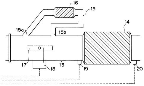
Fig. 1 is a schematic illustration of the construction of an internal
combustion
engine, including its intake-exhaust system, to which the emission control
apparatus of
the invention is applied. The internal combustion engine shown in Fig. 1 is a
four-
stroke four-cylinder internal combustion engine 1. An intake manifold 2 is
connected
to the internal combustion engine 1 in such a manner that each branch pipe of
the
intake manifold 2 communicates with a combustion chamber of a corresponding
one of
the cylinders via a corresponding intake port (not shown).
The intake manifold 2 is connected to a surge tank 3. The surge tank 3 is
connected to an air cleaner box 5 via an intake pipe 4. The intake pipe 4 is
provided
with a throttle valve 6 that cooperates with an accelerator pedal (not shown)
to adjust
the flow of intake air through the intake pipe 4. The throttle valve 6 is
provided with a
throttle position sensor 7 that outputs an electric signal in accordance with
the opening
amount of the throttle valve 6.
The intake pipe 4 is provided with an air flow meter 8 that outputs an
electric
signal corresponding to the mass of intake air flowing through the intake pipe
4. The
surge tank 3 is provided with a vacuum sensor 24 that outputs an electric
signal in
accordance with the pressure in the surge tank 3.
Each branch pipe of the intake manifold 2 is provided with a fuel injection
valve 10a, 10b, 10c, lOd (hereinafter, collectively referred to as "fuel
injection
valves 10"). The fuel injection valves 10 are connected to a fuel distributing
pipe 9.
The fuel distributing pipe 9 distributes fuel pumped thereto by a fuel pump
(not shown)
to the individual fuel injection valves 10.
The fuel injection valves 10 are provided with drive circuits 11 a, 11 b, 11
c, 11 d
(hereinafter, collectively referred to as "drive circuits 11 "), respectively.
When a drive
circuit 11 applies a drive current to its corresponding fuel injection valve
10, the fuel
9
CA 02291900 1999-12-08
TFN990085-CA
injection valve opens so that fuel supplied from the fuel distributing pipe 9
is injected
toward the intake port of the corresponding cylinder.
An exhaust manifold 12 is connected to the internal combustion engine 1. Each
branch pipe of the exhaust manifold 12 communicates with the combustion
chamber of
the corresponding cylinder via a corresponding exhaust port (not shown). The
exhaust
manifold 12 is connected to an exhaust pipe 13. The exhaust pipe 13 is
connected at its
downstream end to a muffler (not shown).
A three-way catalyst device 14 is provided in the pathway of the exhaust
pipe 13, as an exhaust gas-purifying catalyst device according to the
invention. The
three-way catalyst device 14 is formed by a ceramic support that is formed
from
cordierite into a grating configuration having a plurality of through-holes
extending in
the flowing direction of exhaust gas, and a catalyst layer coated on a surface
of the
ceramic support. The catalyst layer is formed by loading a surface of a porous
alumina
(A1203) material having many pores, with platinum-rhodium (Pt-Rh)-based
precious
metal catalysts.
The three-way catalyst device 14 activates when the temperature thereof is
equal to or higher than a predetermined temperature. If the exhaust air-fuel
ratio
flowing into the three-way catalyst device 14 is near the theoretical air-fuel
ratio, the
three-way catalyst device 14 causes hydrocarbons (HC) and carbon monoxide (CO)
present in exhaust gas to react with oxygen OZ present in exhaust gas and
thereby
oxidizes HC and CO into H20 and C02, and causes NOx present in exhaust gas to
react
with HC and CO present in exhaust gas and thereby reduces NOx into H20, C02
and
N2.
A portion of the exhaust pipe 13 extending upstream of the three-way catalyst
device 14 is provided with an upstream air-fuel ratio sensor 19 that outputs
an electric
signal corresponding to the air-fuel ratio of exhaust gas flowing into the
three-way
catalyst device 14. A portion of the exhaust pipe 13 extending downstream of
the
three-way catalyst device 14 is provided with a downstream air-fuel ratio
sensor 20 that
outputs an electric signal corresponding to the air-fuel ratio of exhaust gas
let out of the
three-way catalyst device 14.
Each of the upstream air-fuel ratio sensor 19 and the downstream air-fuel
ratio
sensor 20 is, for example, a sensor that is substantially made up of a tubular
solid
electrolyte portion formed by firing zirconia (Zr02), an outside platinum
electrode
CA 02291900 1999-12-08
TFN990085-CA
covering an outside surface of the solid electrolyte portion, and an inside
platinum
electrode covering an inside surface of the solid electrolyte portion.
Additionally, each
sensor outputs an electric current proportional to the oxygen concentration in
exhaust
gas (i.e., the concentration of unburned gas components if the air-fuel ratio
is in the rich
side of the theoretical air-fuel ratio) as oxygen ions migrate upon
application of a
voltage between the electrodes.
A bypass passage 15 bypassing a portion of the exhaust pipe 13 is connected to
a portion of the exhaust pipe 13 extending upstream of the three-way catalyst
device 14. Provided in the pathway of the bypass passage 15 is an adsorbent 16
that
adsorbs unburned gas components of exhaust gas when the temperature of the
adsorbent 16 is below a predetermined temperature and that releases unburned
gas
components from adsorption at or above the predetermined temperature.
An exhaust gas inlet portion 15a and an exhaust gas outlet portion 1 Sb of the
bypass passage 15 are connected to the exhaust pipe 13 at adjacent positions.
A
portion of the exhaust pipe 13 located between the exhaust gas inlet portion 1
Sa and the
exhaust gas outlet portion 1 Sb, that is, a portion of the exhaust pipe 13
bypassed by the
bypass passage 15, is provided with an open-close valve 17 that opens and
closes the
passage of the exhaust pipe 13. The open-close valve 17 is provided with an
actuator 18 that is formed by a stepper motor and the like so as to open or
close the
open-close valve 17 in accordance with the magnitude of a current applied
thereto. The
open-close valve 17 and the actuator 18 form a passage switching device
according to
this embodiment of the invention.
The exhaust gas inlet portion 15a and the exhaust gas outlet portion 15b of
the
bypass passage 15 are disposed in such a manner that when the open-close valve
17 is
fully opened, the difference between the exhaust gas pressure near the exhaust
gas inlet
portion 15a and the exhaust gas pressure near the exhaust gas outlet portion
15b is 2
kPa or less and, more preferably, 1 kPa or less.
It is also preferred that the exhaust gas inlet portion 15a and the exhaust
gas
outlet portion 15b of the bypass passage 15 be disposed at such positions that
the ratio
between the exhaust gas flow through the exhaust pipe 13 and the exhaust gas
flow
through the bypass passage 15 becomes equal to or less than a predetermined
value
regardless of the operating condition of the internal combustion engine 1.
This position
setting is preferable in order to limit, to a predetermined range, the rate of
the change of
I1
CA 02291900 1999-12-08
TFN990085-CA
the air-fuel ratio that is caused by unburned gas components mixing into
exhaust gas
when unburned gas components are desorbed from the adsorbent 16, regardless of
the
operating condition of the internal combustion engine 1. More specifically, an
upper
limit of the amount of unburned gas components discharged from the bypass
S passage 15 into the exhaust pipe 13 in a unit time is determined such that
the air-fuel
ratio of a mixture gas of unburned gas components desorbed from the adsorbent
16 and
exhaust gas remains within a range that allows the three-way catalyst device
14 to
sufficiently purify the mixture gas.
In the case of a vehicle in which the air-fuel ratio feedback control is
performed,
the upper limit is determined such that the emission quality is not further
degraded,
because changes in the air-fuel ratio of the mixture gas change the air-fuel
ratio of a fuel
mixture gas in the internal combustion engine 1. The positional relationship
between
the exhaust gas inlet portion 15a and the exhaust gas outlet portion 15b of
the bypass
passage 15 is determined so that the ratio between the flow of exhaust gas
through the
exhaust pipe 13 and the flow of exhaust gas through the bypass passage 15 will
not
exceed the upper limit. Furthermore, when sent into the bypass passage 15,
exhaust gas
increases the temperature of the adsorbent 16. In order to prevent
deterioration of
emission quality, it is necessary that the temperature of the three-way
catalyst device 14
reach or exceed an activation temperature that allows the three-way catalyst
device 14
to significantly lessen unburned gas components, before unburned gas
components are
desorbed from the adsorbent 16 due to a temperature increase in the adsorbent
16. The
warming of the adsorbent 16 and the warming of the three-way catalyst device
14
depends on the flows of exhaust gas through the adsorbent 16 and the three-way
catalyst device 14, respectively. Therefore, the upper limit of the ratio
between the
exhaust gas flow through the exhaust pipe 13 and the exhaust gas flow through
the
bypass passage 15 is determined so that the three-way catalyst device 14
assumes the
activation temperature before the adsorbent starts desorbing unburned gas
components.
In this embodiment, the arrangement of the exhaust gas inlet portion 1 Sa and
the
exhaust gas outlet portion 1 Sb of the bypass passage 15 is determined so that
the ratio
between the exhaust gas flow through the bypass passage 15 and the exhaust gas
flow
through the exhaust pipe 13 always remains equal to or less than 10% and, more
preferably, equal to or less than 1 %, regardless of the operating condition
of the internal
combustion engine.
12
CA 02291900 1999-12-08
TFN990085-CA
The internal combustion engine 1 has a crank position sensor 21 that outputs a
pulse signal at every predetermined rotational angle (e.g., 30°) of a
crankshaft (not
shown), and a water temperature sensor 22 that outputs an electric signal
corresponding to the temperature of cooling water flowing in a water jacket
(not shown)
of the internal combustion engine 1.
The crank position sensor 21, the water temperature sensor 22, the throttle
position sensor 7, the air flow meter 8, the vacuum sensor 24, the upstream
air-fuel
ratio sensor 19 and the downstream air-fuel ratio sensor 20 are connected to
an
engine-controlling electronic control unit (ECU) 25 by their respective
wirings so that
the signal from each sensor is input to the ECU 25. Using the output signals
of the
sensors, the ECU 25 determines an operating condition of the internal
combustion
engine 1. In accordance with the determined operating condition, the ECU 25
performs various controls such as the fuel injection control, the ignition
control, the
open-close control of the open-close valve 17, and the like.
Referring to Fig. 2, the ECU 25 has a CPU 27, a ROM 28, a RAM 29, a backup
RAM 30, an input port 31, and an output port 32 that are interconnected by a
bi-
directional bus 26. The ECU 25 further has an A/D converter 33 that is
connected to
the input port 31.
The input port 31 receives output signals of the crank position sensor 21 and
the
like, and sends the output signals to the CPU 27 and to the RAM 29. The input
port 31
also receives output signals of the throttle position sensor 7, the air flow
meter 8, the
upstream air-fuel ratio sensor 19, the downstream air-fuel ratio sensor 20,
the water
temperature sensor 22, the vacuum sensor 24 and the like, via the A/D
converter 33,
and sends the output signals to the CPU 27 and to the RAM 29.
The output port 32 sends control signals from the CPU 27 to the actuator 18
and to the drive circuits 11.
The ROM 28 stores application programs of, for example, a fuel injection
amount control routine for determining an amount of fuel to be injected from
each fuel
injection valve 10, an air-fuel ratio feedback control routine for executing
the air-fuel
ratio feedback control of the fuel injection amount, a fuel injection timing
control
routine for determining a fuel injection timing of each fuel injection valve
10, a passage
switch control routine for controlling the open-close valve 17, and the like.
The
ROM 28 also stores various control maps.
13
CA 02291900 1999-12-08
TFN990085-CA
The control maps include, for example, a fuel injection amount control map
indicating a relationship between the fuel injection amount and the operating
condition
of the internal combustion engine 1, a fuel injection timing control map
indicating a
relationship between the fuel injection timing and the operating condition of
the
internal combustion engine 1, an activation determination control map
indicating a
relationship between the temperature of cooling water at the time of start of
the internal
combustion engine and the amount of time needed between the start of the
engine and
activation of the three-way catalyst device 14 (hereinafter, referred to as
"catalytic
activation time"), and the like.
The RAM 29 stores output signals from the various sensors, results of
operations of the CPU 27, and the like. The results of operations include, for
example,
an engine revolution speed calculated from the output signal of the crank
position
sensor 21, and the like. The output signals of the various sensors, the
results of
operations of the CPU 27, and the like are rewritten to latest data every time
the crank
position sensor 21 outputs a signal.
The backup RAM 30 is a non-volatile memory capable of retaining data even
after the internal combustion engine 1 is stopped.
The CPU 27 operates in accordance with the application programs stored in the
ROM 28, and determines an operating condition of the internal combustion
engine 1
on the basis of the output signals of the sensors stored in the RAM 29, and
calculates a
fuel injection amount, a fuel injection timing, an opening or closing timing
of the
open-close valve 17, and the like on the basis of the determined operating
condition of
the internal combustion engine l and the various control maps. Based on the
fuel
injection amount, the fuel injection timing, the opening or closing timing of
the open-
close valve 17, and the like, the CPU 27 controls the drive circuits 11 and
the
actuator 18.
For example, to perform the fuel injection control, the CPU 27 follows the
fuel
injection amount control routine, and determines a fuel injection amount (TAU)
by the
following equation:
TAU = TP * FWL * (FAF + FG) * [FASE + FAE + FOTP + FDE(D)] * FFC +
TAUV
TP: basic injection amount
FWL: warm-up increase
14
CA 02291900 1999-12-08
TFN990085-CA
FAF: air-fuel ratio feedback correction factor
FG: air-fuel ratio learned factor
FASE: increase after start
FAE: acceleration increase
FOTP: OTP (Over Temperature Protection) increase
FDE(D): deceleration increase (decrease)
FFC: correction factor at the time of fuel cut return
TAUV: invalid fuel injection duration
For the evaluation of the above equation, the CPU 27 determines an operating
condition of the internal combustion engine 1 by using the values of output
signals of
the sensors as parameters. Based on the determined operating condition of the
internal
combustion engine 1 and the fuel injection amount control map stored in the
ROM 28,
the CPU 27 calculates the basic injection amount (TP), the warm-up increase
(FWL),
the increase after start (FASE), the acceleration increase (FAE), the OTP
increase
(FOTP), the deceleration increase (FDE(D)), the correction factor at the time
of fuel cut
return (FFC), the invalid injection duration (TAUV), and the like.
Furthermore, the CPU 27 calculates an air-fuel ratio feedback correction
factor
(FAF) by following the air-fuel ratio feedback control routine as shown in
Fig. 3. In the
air-fuel ratio feedback control routine illustrated in Fig. 3, the CPU 27
first determines
in step 5301 whether an air-fuel ratio feedback control condition has been
established.
Examples of the air-fuel ratio feedback control condition include a condition
that the
cooling water temperature is equal to or higher than a predetermined
temperature, a
condition that the internal combustion engine 1 is not started, a condition
that the
increasing correction of the fuel injection amount after start of the engine
is not
performed, a condition that the warm-up increasing correction of the fuel
injection
amount is not performed, a condition that the acceleration increasing
correction of the
fuel injection amount is not performed, a condition that the OTP increasing
correction
for preventing overheating of exhaust-system component parts, such as the
three-way
catalyst device 14, is not performed, a condition that the fuel cut control is
not
performed, and the like.
If the CPU 27 determines in step 5301 that the air-fuel ratio feedback control
condition as mentioned above is not satisfied, the CPU 27 sets the air-fuel
ratio
CA 02291900 1999-12-08
TFN990085-CA
feedback correction factor (FAF) to 1.0, and temporarily ends the execution of
the
routine.
If it is determined in step 5301 that the air-fuel ratio feedback control
condition
is satisfied, the CPU 27 goes to step 5302, in which the CPU 27 inputs the
value of an
output signal of the upstream air-fuel ratio sensor 19 via the A/D converter
33. In step
5303, the CPU 27 determines whether the actual exhaust air-fuel ratio is in
the fuel-rich
(or fuel-lean) side of the theoretical air-fuel ratio on the basis of the
values of output
signals input in step 5302 and the response delay time of the upstream air-
fuel ratio
sensor 19. If it is determined in step 5303 that the exhaust air-fuel ratio is
in the rich
side of the theoretical air-fuel ratio, the CPU 27 goes to step 304, in which
the CPU 27
corrects the value of the air-fuel ratio feedback correction factor (FAF) so
as to perform
the decreasing correction of the fuel injection amount (TAU). If it is
determined in step
5303 that the exhaust air-fuel ratio is in the lean side of the theoretical
air-fuel ratio, the
CPU 27 goes to step S305, in which the CPU 27 corrects the value of the air-
fuel ratio
feedback correction factor (FAF) so as to perform the increasing correction of
the fuel
injection amount (TAU).
ABer executing step 5304 or step 5305, the CPU 27 goes to step 5306, in which
the CPU 27 performs an upper limit guarding process and a lower limit guarding
process on the air-fuel ratio feedback correction factor (FAF) calculated in
step 5304 or
step 5305. Subsequently in step S307, the CPU 27 stores the air-fuel ratio
feedback
correction factor guard-processed in step 5304 or step 5305 into a
predetermined area
in the RAM 29. Then, the CPU 27 temporarily ends the execution of the routine.
Concurrently with the air-fuel ratio feedback control (first air-fuel ratio
feedback control) based on output signals of the upstream air-fuel ratio
sensor 19 as
described above, the CPU 27 executes an air-fuel ratio feedback control
(second air-
fuel ratio feedback control) based on output signals of the downstream air-
fuel ratio
sensor 20.
In the second air-fuel ratio feedback control, the CPU 27 compares the value
of
an output signal of the downstream air-fuel ratio sensor 20 with a
predetermined
reference voltage to determine whether the air-fuel ratio of exhaust gas
flowing out of
the three-way catalyst device 14 is a fuel-lean ratio or a fuel-rich ratio.
Based on the
determination, the CPU 27 corrects a criterion value for the rich/lean
determination in
the first air-fuel ratio feedback control, a correction amount of the air-fuel
ratio
16
CA 02291900 1999-12-08
TFN990085-CA
feedback correction factor (FAF), and the like. Thereby, the CPU 27 curbs, for
example, the deterioration of emissions caused by variations in the output
characteristic of the upstream air-fuel ratio sensor 19 due to differences
among
individual sensors, changes in the output characteristic of the upstream air-
fuel ratio
sensor 19 due to aging, and the like.
Subsequently, for the control of the open-close valve 17, the CPU 27 inputs an
output signal of the water temperature sensor 22, and calculates a catalytic
activation
time based on the output signal of the water temperature sensor 22 and the
activation
determination control map stored in the ROM 28, when the internal combustion
engine 1 is started. The CPU 27 then outputs a control signal to the actuator
18 so as to
maintain a completely closed state of the open-close valve 17 (a non-
conductive state
of the exhaust pipe 13) as shown in Fig. 1 until the catalytic activation time
elapses,
that is, while the three-way catalyst device 14 is in a not-activated state.
The entire
amount of exhaust gas discharged from the internal combustion engine 1 is led
to the
bypass passage 15 so as to pass through the adsorbent 16 before flowing into
the
three-way catalyst device 14. Therefore, unburned gas components contained in
exhaust gas are not let out into the atmosphere, but are adsorbed by the
adsorbent 16.
After the catalytic activation time elapses, that is, after the three-way
catalyst
device 14 activates, the CPU 27 outputs a control signal to the actuator 18 so
as to
establish a fully open state of the open-close valve 17 (a conductive state of
the exhaust
pipe 13) as shown in Fig. 4.
In this situation, both the exhaust pipe 13 and the bypass passage 15 are in
the
conductive state, so that exhaust gas discharged from the internal combustion
engine 1
flows parallel through the bypass passage 15 and the exhaust pipe 13 before
flowing
into the three-way catalyst device 14.
Since the exhaust gas inlet portion 1 Sa and the exhaust gas outlet portion 1
Sb of
the bypass passage 15 are adjacent to each other, the difference between the
exhaust
gas pressure near the exhaust gas inlet portion 1 Sa and the exhaust gas
pressure near the
exhaust gas outlet portion 15b is small, and the phase difference between the
pulsating
flow of exhaust gas through a portion of the exhaust pipe 13 located near the
exhaust
gas inlet portion 1 Sa and the pulsating flow of exhaust gas through a portion
of the
exhaust pipe 13 located near the exhaust gas outlet portion 15b is small.
Therefore, of
the entire amount of exhaust gas discharged from the internal combustion
engine 1,
17
CA 02291900 1999-12-08
TFN990085-CA
only a very small portion flows into the three-way catalyst device 14 via the
bypass
passage 15. Rather, the major portion of the exhaust gas flows into the three-
way
catalyst device 14 via the exhaust pipe 13 without flowing through the bypass
passage
15.
When the flow through the bypass passage 15 is very small, the flow of exhaust
gas through the adsorbent 16 correspondingly becomes very small, so that the
temperature increasing rate of the adsorbent 16 becomes small or gradual.
Therefore,
the unburned gas components adsorbed to the adsorbent 16 are gradually
desorbed
therefrom little by little.
As a result, the amount of unburned gas components introduced from the
bypass passage 15 into a portion of the exhaust pipe 13 upstream of the three-
way
catalyst device 14 becomes very small, so that the air-fuel ratio of exhaust
gas flowing
into the three-way catalyst device 14 will not excessively change (to an
excessively rich
ratio).
Therefore, the air-fuel ratio of exhaust gas flowing into the three-way
catalyst
device 14 will not deviate from a range of air-fuel ratio that allows the
three-way
catalyst device 14 to significantly lessen HC, CO, NOx. Hence, the three-way
catalyst
device 14 reliably achieves significant reductions of the amounts of unburned
gas
components and harmful gas components present in exhaust gas, so that
emissions will
not deteriorate.
Furthermore, since the air-fuel ratio of exhaust gas flowing into the three-
way
catalyst device 14 does not excessively change (to an excessively rich ratio),
the
detection precision of the upstream air-fuel ratio sensor 19 and the
downstream air-fuel
ratio sensor 20 will not decrease. Therefore, it becomes possible to perform
the air-fuel
ratio feedback control with high precision.
If unburned gas components are slowly desorbed from the adsorbent 16 mix
into exhaust gas, the shift of the exhaust air-fuel ratio to a richer ratio
thereby caused is
very small. Therefore, an undesired event in which the air-fuel ratio feedback
control
results in an excessively lean engine air-fuel ratio (air-fuel ratio of a
mixture to be
burned in the cylinder block 1 ) is prevented from occurring, so that an
unstable
operating condition of the internal combustion engine 1 is prevented.
Furthermore, the ratio of the flow of exhaust gas through the bypass passage
15
to the flow of exhaust gas through the exhaust pipe 13 becomes equal to a
substantially
18
CA 02291900 1999-12-08
TFN990085-CA
constant value that is equal to or less than a predetermined value, so that
the rate of the
change in the exhaust air-fuel ratio caused by unburned gas components
desorbed from
the adsorbent 16 mixing into exhaust gas can be stabilized regardless of the
operating
condition of the internal combustion engine 1. Therefore, the air-fuel ratio
feedback
control is not complicated. Hence, stable air-fuel ratio feedback control can
be
realized.
Still further, in the emission control apparatus of this embodiment of the
invention, the ratio of the flow of exhaust gas through the bypass passage 15
to the flow
of exhaust gas through the exhaust pipe 13 becomes a substantially constant
value
equal to or less than the predetermined value without requiring control of the
flow
through the bypass passage 15 when the open-close valve 17 is in a fully open
state.
Therefore, there is no need to provide a flow adjusting valve or the like in
the side of the
inlet to the bypass passage 15. Hence, it becomes possible to simplify the
construction
of the apparatus and the control thereof.
Although in the foregoing embodiment, the open-close valve 17 is kept in the
fully open state after the three-way catalyst device 14 is activated, it is
also possible to
adopt a construction in which the exhaust gas inlet portion 15a and the
exhaust gas
outlet portion 1 Sb of the bypass passage 15 are provided with pressure
sensors and a
pressure difference between the exhaust gas inlet portion 15a and the exhaust
gas outlet
portion 1 Sb is detected based on the difference between the outputs of the
two pressure
sensors. In this construction, the opening amount of the open-close valve 17
is
controlled so that the detected pressure difference becomes equal to a desired
pressure
difference. It is also possible to estimate an amount of unburned gas
components
present in exhaust gas or an air-fuel ratio of exhaust gas flowing downstream
of the
adsorbent 16 (upstream of the three-way catalyst device 14) from the value of
an output
signal of the upstream air-fuel ratio sensor 19 and to control the opening
amount of the
open-close valve 17 so that the amount of unburned gas components or the air-
fuel
ratio becomes constant.
A second embodiment of the internal combustion engine emission control
apparatus of the invention will be described with reference to Figs. 5 to 9.
Features
distinguishing the second embodiment from the first embodiment will mainly be
described, and portions and arrangements comparable to those of the first
embodiment
will not be described again.
19
CA 02291900 1999-12-08
TFN990085-CA
Fig. 5 illustrates an emission control apparatus according to the second
embodiment of the invention. The emission control apparatus shown in Fig. 5
includes
an outer tube I 60 having an inside diameter that is greater than the outside
diameter of
an exhaust pipe 13, an inner tube 161 having an inside diameter greater than
the
outside diameter of the exhaust pipe 13 and having an outside diameter smaller
than the
inside diameter of the outer tube 160, and an annular adsorbent 162 disposed
between
the inner tube 161 and the outer tube 160.
The exhaust pipe 13 is divided into an upstream exhaust pipe 13a and a
downstream exhaust pipe 13b that are spaced apart from each other within the
outer
tube 160. The upstream exhaust pipe 13a and the downstream exhaust pipe 13b
are
interconnected by the outer tube 160.
The downstream exhaust pipe 13b is connected to the outer tube 160 so that an
upstream-side open end portion of the downstream exhaust pipe 13b extends into
the
outer tube 160 and a distal end thereof is a free (not fixed) end.
Correspondingly, the
inner tube 161 is held within the outer tube 160 in such a manner that one end
of the
inner tube 161 is fixed to one of the outer tube 160, the exhaust pipe 13 and
a valve
device 170 (described below) and the other end of the inner tube 161 is not
fixed to any
one of the outer tube 160, the exhaust pipe 13 and the valve device 170, and
that an
upstream-side end portion of the inner tube 161 extends further upstream of
the
upstream-side end of the downstream exhaust pipe 13b.
This construction is adopted for the following reasons. The outer tube 160 is
fixed to the upstream exhaust pipe 13a and the downstream exhaust pipe 13b.
The
outer tube 160 is likely to have a lower temperature than the inner tube 161
and the
downstream exhaust pipe 13b. Therefore, if both ends of the inner tube 161 or
the
upstream-side end of the downstream exhaust pipe 13b is fixed to the outer
tube 160
directly or indirectly via the valve device 170, different thermal expansion
rates of the
outer tube 160, the inner tube 161 and the downstream exhaust pipe 13b will
likely
break the emission control apparatus, thereby degrading its durability.
The adsorbent 162 is fixed to only one of the outer tube 160 and the inner
tube 161 in this embodiment. This construction is adopted for the following
reasons. If
the adsorbent 162 is fixed to both the outer tube 160 and the inner tube 161,
different
magnitudes of thermal expansion of the outer tube 160 and the inner tube 161
caused
CA 02291900 1999-12-08
TFN990085-CA
by different temperatures of the two tubes create a tensile force or a
compressive force
on the adsorbent 162, so that the adsorbent 162 may break.
Retaining members 163 are disposed at plural locations in a space formed
between the inner tube 161 and the downstream exhaust pipe 13b as shown in
Fig. 6, in
order to enhance the vibration resistance of the downstream exhaust pipe 13b.
Each of
the retaining members 163 may be fixed to only one of the inner wall surface
of the
inner tube 161 and the outer wall surface of the downstream exhaust pipe 13b.
In this
construction, therefore, the adsorbent 162 and the downstream exhaust pipe 13b
are
associated with each other in a non-fixed state, so that the difference
between thermal
expansion of the downstream exhaust pipe 13b in a direction of the axis
thereof and
thermal expansion of the inner tube 161 in a direction of the axis can be
absorbed.
The retaining members 163 may be formed by compressing a wire mesh
material, so that differences in radial thermal expansion between the inner
tube 161 and
the downstream exhaust pipe 13b can also be absorbed. It is also possible to
use
honeycomb pieces as the retaining members 163 and to coat the honeycomb pieces
with an adsorbent. As a result, the unburned gas component-adsorbing capacity
can be
increased without changing the configuration or size of the entire apparatus.
The valve device 170 is provided at the upstream-side open end of the inner
tube 161. The valve device 170 opens and closes the open end of the inner tube
161.
The valve device 170 is formed by a butterfly-type two-way valve as shown in
Fig. 7.
More specifically, the valve device 170 has a housing 171 that is fitted into
the
upstream-side open end portion of the inner tube 161, a passage 174 extending
through
the housing 171 in the directions of an axis thereof, a valve body 172 that
opens and
closes the passage 174, and a shaft 173 connected to the valve body 172.
The shaft 173 is rotatably supported at one end thereof by the housing 171,
and
is rotatably supported at the second end by a bearing 175 that is provided on
the outer
wall surface of the outer tube 160. The second end of the shaft 173 is
connected to the
actuator 18 via a link mechanism and the like.
In the emission control apparatus constructed as described above, the valve
body 172 assumes a completely closed state when the three-way catalyst device
14 is
not activated. In this situation, exhaust gas from the upstream exhaust pipe
13a is led
into an annular space 164 formed between the inner tube 161 and the outer tube
160,
and then flows into the adsorbent 162. After flowing out of the adsorbent 162,
exhaust
21
CA 02291900 1999-12-08
TFN990085-CA
gas strikes an inner wall surface of the outer tube 160, and therefore changes
its flowing
direction. Exhaust gas is then led into an annular space 165 formed between
the inner
tube 161 and the downstream exhaust pipe 13b. After passing through the space
165,
exhaust gas strikes the valve device 170 and changes its flowing direction (as
indicated
at 166) to flow into the downstream exhaust pipe 13b.
After the three-way catalyst device 14 is activated, the valve body 172
assumes
a fully open state. In this situation, an exhaust passage (main exhaust
passage)
extending ftom the upstream exhaust pipe 13a to the downstream exhaust pipe
13b via
the passage 174 of the valve device 170 disposed within the outer tube 160
becomes
conductive, and the exhaust passage (bypass passage) extending from the
upstream
exhaust pipe 13a to the downstream exhaust pipe 13b via the space 164 and the
space 165 becomes conductive.
An exhaust gas inlet portion of the space 164 and an exhaust gas outlet
portion
of the space 165 are located adjacent to each other across the valve device
170.
Therefore, the difference between the exhaust gas pressure near the exhaust
gas inlet
portion of the space 164 and the exhaust gas pressure near the exhaust gas
outlet
portion of the space 165 becomes small, and the phase difference between the
pulsating
flow of exhaust gas near the exhaust gas inlet portion of the space 164 and
the pulsating
flow of exhaust gas near the exhaust gas outlet portion of the space 165 also
becomes
small.
In the emission control apparatus of this embodiment, the inside diameter (D1)
of the upstream exhaust pipe 13a, the diameter (D2) of the passage 174 through
the
housing 171, and the inside diameter (D3) of the downstream exhaust pipe 13b
are set
so as to satisfy D1 <_ D2 <_ D3 and, preferably, D1 < D2 <_ D3. The
relationship D1 < D2
is preferable for the following reason. Even if the valve body 172 is fully
open, the
cross-section of the passage 174 has a reduced area due to the thickness of
the valve
body 172 and the diameter of the shaft 173. The pressure loss thereby caused
can be
practically eliminated if the relationship D1 < D2 is established. The reason
for the
relationship D2 <_ D3 is that if D2 > D3, the pressure in a space between the
valve
device 170 and the downstream exhaust pipe 13b within the inner tube 161 will
increase so that the flow through the bypass passage 164, 165 may reverse.
An object of the invention is to slow down the desorption of unburned gas
components by reducing the flow of exhaust gas passing through the adsorbent.
Even if
22
CA 02291900 1999-12-08
TFN990085-CA
the flow through the bypass passage 164, 165 reverses, the object of the
invention can
be achieved provided that the flow is sufficiently small. Therefore, it is
also possible to
allow a reverse flow through the bypass passage 164, 165 as long as the flow
therethrough is a desired flow. That is, a requirement is merely that the
pressure
difference between the exhaust gas inlet portion and the exhaust gas outlet
portion of
the bypass passage 164, 165 be small so that the flow through the bypass
passage may
be sufficiently small.
If the valve device 170 and the upstream exhaust pipe 13a are disposed apart
from each other in the emission control apparatus described above, the
distance (L1)
between the valve device 170 and the upstream exhaust pipe 13a may be set so
as to
satisfy (D2 - D1) * 0.5 <_ L1 and, preferably, D2 - D1 <_ L1. This option is
based on a
finding of the inventors that an undesired event occurs in which, depending on
the
velocity of flow of gas out of the upstream exhaust pipe 13a, a negative
pressure occurs
in an outlet portion of the upstream exhaust pipe 13a so that the pressure in
the
space 164 also becomes negative and causes a reverse flow of gas through the
bypass
passage 164, 165 can be prevented by arranging the valve device 170 and the
upstream
exhaust pipe 13a in such a manner as to satisfy the experimentally determined
relationship mentioned above because that manner of arrangement substantially
prevents the negative pressure in the outlet portion of the upstream exhaust
pipe 13a
from affecting the pressure in the space 164 and therefore prevents a reverse
flow of gas
through the bypass passage 164, 165.
As a result, a major portion of exhaust gas from the upstream exhaust pipe 13a
flows through the exhaust passage extending from the upstream exhaust pipe 13a
to the
downstream exhaust pipe 13b via the passage 174, and the small remainder
portion of
exhaust gas flows through the exhaust passage extending from the upstream
exhaust
pipe 13a to the downstream exhaust pipe 13b via the space 164 and the space
165.
Therefore, the emission control apparatus of this embodiment achieves
substantially the same advantages as achieved by the first embodiment and,
furthermore, allows a size reduction of the entire emission control apparatus
and
thereby considerably facilitates installation of the apparatus into a vehicle.
Furthermore, this embodiment adopts an arrangement in which the adsorbent
and the bypass passage are disposed coaxially with the main exhaust passage.
Since the
adsorbent and the main exhaust passage are separated from each other by a
space that
23
CA 02291900 1999-12-08
TFN990085-CA
forms the bypass passage, the space serves as a heat-insulating portion to
reduce heat
conduction from the main exhaust passage to the adsorbent. As a result, the
temperature increase of the adsorbent is gradual, so that the desorption of
unburned gas
components slows down.
Still further, the embodiment employs the butterfly-type two-way valve as a
passage switching device according to the invention. The valve body of the
butterfly-
type two-way valve receives, from exhaust gas, a force that expedites the
turning of the
valve body on one of the halves of the valve body divided by the rotating axis
thereof,
and a force that opposes the turning of the valve body on the other half.
However, the
two forces balance each other. Therefore, the actuator can drive the valve
body without
being affected by exhaust gas, so that the load on the actuator is reduced. As
a result, a
size reduction of the actuator is allowed, so that the installation of the
valve device,
including the actuator, can be further facilitated.
However, the passage switching device is not limited to the butterfly-type
two-way valve. For example, a slide valve may instead be used in order to
reduce the
resistance caused by exhaust gas when the valve is fully opened.
Although in the second embodiment, dedicated retainers 163 are disposed at
plural positions in the space formed between the inner tube 161 and the
downstream
exhaust pipe 13b in order to enhance the vibration resistance of the
downstream
exhaust pipe 13b, it is also possible to emboss semi-spherical protrusions 167
at plural
positions in a member forming the inner tube 161 as shown in Figs. 8 and 9 so
that the
protrusions 167 serve as retainers. It is preferred that the shape, number and
position of
such retainers be determined so as to achieve a desired flow through the
bypass
passage.
A third embodiment of the internal combustion engine emission control
apparatus of the invention will be described with reference to Fig. 10.
Features
distinguishing the third embodiment ftom the second embodiment will mainly be
described, and portions and arrangements comparable to those of the second
embodiment will not be described again.
Fig. 10 illustrates an emission control apparatus according to the third
embodiment of the invention. In the emission control apparatus shown in Fig.
10, an
upstream exhaust pipe 13a and a downstream exhaust pipe 13b are interconnected
by a
valve device 170 within an outer tube 160. A portion of the upstream exhaust
pipe 13a
24
CA 02291900 1999-12-08
TFN990085-CA
adjacent to a downstream-side end of the upstream exhaust pipe 13a has exhaust
gas
inlets 130 for communication between the inside of the upstream exhaust pipe
13a and
the outside thereof (i.e., a space 164 defined between the upstream exhaust
pipe 13a
and the outer tube 160). The exhaust gas inlets 130 are arranged at
predetermined
intervals in a circumferential direction. A portion of the downstream exhaust
pipe 13b
adjacent to an upstream-side end of the downstream exhaust pipe 13b has
exhaust gas
outlets 131 for communication between the inside of the downstream exhaust
pipe 13b
and the outside thereof (i.e., a space 165 defined between the downstream
exhaust
pipe 13b and an inner tube 161). The exhaust gas outlets 131 are arranged at
predetermined intervals in a circumferential direction.
The clearance between a downstream-side end portion of the inner tube 161 and
a downstream-side end portion of the outer tube 160 is enlarged to form a
space 168.
The thus-formed space 168 serves as a damper chamber to damp the exhaust
pulsation
phase difference that occurs between an exhaust gas inlet portion (the exhaust
gas
inlets 130) and an exhaust gas outlet portion (the exhaust gas outlets 13 I )
of a bypass
passage 164, 165.
In the emission control apparatus constructed as described above, the damper
chamber damps the exhaust pulsation phase difference between the exhaust gas
inlets 130 and the exhaust gas outlets 131 even if the phase difference
instantly
increases, as occurs when the flow of exhaust gas from the internal combustion
engine 1 sharply changes. Therefore, the embodiment prevents an undesired
event
from occurring in which the difference between the exhaust gas pressure near
the
exhaust gas inlets 130 and the exhaust gas pressure near the exhaust gas
outlets 131
significantly increases, and ensures that the flow of exhaust gas through the
adsorbent 162 will always be small.
Furthermore, with the construction described above, the pressure difference
between the exhaust gas inlets 130 and the exhaust gas outlets 131 can easily
be set to a
desired magnitude by adjusting the shape, number or diameter of the exhaust
gas
inlets 130 and the exhaust gas outlets 131 in a production process of the
emission
control apparatus.
A fourth embodiment of the internal combustion engine emission control
apparatus of the invention will be described with reference to Fig. 11.
Features
distinguishing the fourth embodiment from the second embodiment will mainly be
CA 02291900 1999-12-08
TFN990085-CA
described, and portions and arrangements comparable to those of the second
embodiment will not be described again.
Fig. 11 illustrates an emission control apparatus according to the fourth
embodiment of the invention in which an exhaust gas-purifying catalyst device
and an
adsorbent are coaxially arranged. In the emission control apparatus shown in
Fig. 11, a
portion of a downstream exhaust pipe 13b extending into an outer tube 160 has
an
increased inside diameter. This expanded portion of the downstream exhaust
pipe 13b
contains a three-way catalyst device 14. The three-way catalyst device 14 in
this
construction is disposed upstream of the position of the three-way catalyst
device in the
first to third embodiments. Therefore, the three-way catalyst device 14 in the
fourth
embodiment is exposed to higher-temperature exhaust gas than the three-way
catalyst
device in any of the first to third embodiments, so that the three-way
catalyst device 14
can be activated more quickly.
Furthermore, the three-way catalyst device 14 is surrounded by a space 165
(bypass passage) in the fourth embodiment. Therefore, the space 165 serves as
a heat
insulating portion to block heat radiation from the three-way catalyst device
14. As a
result, the thermal insulation of the three-way catalyst device 14 improves,
and the
overheat deterioration of an adsorbent 162 disposed in a space 164 between the
outer
tube 160 and an inner tube 161 is prevented.
Still further, since the three-way catalyst device 14 is disposed coaxially
with
the bypass passage 164, 165 and the adsorbent 162, these components and the
like can
be closely packed. As a result, a size reduction of the emission control
apparatus is
allowed, so that the installation of the apparatus into a vehicle is further
facilitated.
If there is a need to reduce the outside diameter of the emission control
apparatus for installation into a vehicle, the adsorbent 162 may be disposed
around a
portion of the exhaust pipe 13 extending downstream of the three-way catalyst
device 14 as shown in Fig. 12. This construction makes it possible to activate
the
three-way catalyst device 14 in an earlier period. Furthermore, in the
construction
shown in Fig. 12, the length of the bypass passage is increased, so that the
temperature
of exhaust gas flowing into the adsorbent 16 becomes lower. Therefore, the
temperature increasing rate of the adsorbent 16 is further reduced, so that
the
desorption of unburned gas components correspondingly slows down.
26
CA 02291900 1999-12-08
TFN990085-CA
A fifth embodiment of the internal combustion engine emission control
apparatus of the invention will be described with reference to Figs. 13 and
14. Features
distinguishing the fifth embodiment from the second embodiment will mainly be
described, and portions and arrangements comparable to those of the second
embodiment will not be described again.
Figs. 13 and 14 illustrate an emission control apparatus according to the
fifth
embodiment of the invention. In the emission control apparatus of this
embodiment, an
outer tube 160 contains a honeycomb body in which a plurality of exhaust
passages are
joined. The honeycomb body is divided into three coaxial divisions 190, 191,
192. Of
the three honeycomb divisions 190, 191, 192, a central honeycomb division 190
is
loaded with catalysts, and an outermost honeycomb division 192 is coated with
an
adsorbent. An intermediate honeycomb division 191 may be coated with an
adsorbent
or may be left uncoated.
Since such a honeycomb body is used, the emission control apparatus can be
constructed without requiring an inner tube. Therefore, size and weight
reductions of
the apparatus can be achieved.
The method for producing the above-described emission control apparatus may
be, for example, a method in which the outermost honeycomb division 192 is
coated
with an adsorbent while the inlet and outlet openings of the passages through
the
central and intermediate honeycomb divisions 190, 191 are closed, and the
central
honeycomb division 190 is coated with catalysts while the inlet and outlet
openings of
the passages through the intermediate and outermost honeycomb divisions 191,
192
are closed. Alternatively, the apparatus can be produced by a method in which
the
central and outermost honeycomb divisions 190, 192 are subjected to multi-
layer
coating with catalysts and an adsorbent (respectively) while only the passages
through
the intermediate honeycomb division 191 are closed. As another option, the
apparatus
can be produced by a method in which the central and outermost honeycomb
divisions 190, 192 are coated with catalysts while the passages through the
intermediate honeycomb division 191 are closed, and then only the outermost
honeycomb division 192 is coated with an adsorbent while the passages through
the
central and intermediate honeycomb divisions 190, 191 are closed, and the
like.
Therefore, this embodiment can provide a small-size and light-weight emission
control apparatus that is easy to produce.
27
CA 02291900 1999-12-08
TFN990085-CA
In the foregoing embodiments, the flow through the bypass passage, that is,
the
flow of exhaust gas passing through the adsorbent, is controlled to become
equal to or
less than a predetermined amount. Therefore, the temperature increasing rate
of the
adsorbent is reduced, so that the desorption of unburned gas components from
the
adsorbent slows down.
As a result, the embodiments prevent an undesired event from occurring in
which the unburned gas components adsorbed to the adsorbent are desorbed from
the
adsorbent and flow into the exhaust gas-purifying catalyst device in large
amounts at
one time (i.e., in unison). Hence, the air-fuel ratio of exhaust gas flowing
into the
exhaust gas-purifying catalyst device is substantially prevented from becoming
a rich
air-fuel ratio in which the oxygen storing capacity of the exhaust gas-
purifying catalyst
device is exceeded or a rich air-fuel ratio that exceeds the detection range
of the air-fuel
ratio sensor, so that the exhaust air-fuel ratio will not deviate from the
range of air-fuel
ratio in which the catalyst device is able to purify exhaust gas.
The flow through the bypass passage, that is, the flow of exhaust gas passing
through the adsorbent, is controlled so that the flow assumes a substantially
constant
proportion to the flow through the main exhaust passage, the substantially
constant
proportion being equal to or less than a predetermined value. Therefore, even
if the
flow of exhaust gas from the internal combustion engine changes, the change in
the
air-fuel ratio of exhaust gas flowing into the exhaust gas-purifying catalyst
device is
substantially prevented.
Therefore, when applied to an internal combustion engine which employs an
adsorbent that adsorbs unburned gas components present in exhaust gas, the
foregoing
embodiments are able to prevent an undesired event from occurring in which
unburned
gas components adsorbed to the adsorbent are desorbed therefrom and flow into
the
exhaust gas-purifying catalyst device in unison. Therefore, the air-fuel ratio
of exhaust
gas flowing into the exhaust gas-purifying catalyst device can be stabilized,
so that the
exhaust gas-purifying catalyst device can reliably achieve significant
reductions of the
amounts of harmful gas components and unburned gas components present in
exhaust
gas. As a result, deterioration of emissions caused by unburned gas components
desorbed from the adsorbent can be prevented.
If the invention is applied to an internal combustion engine in which feedback
control is performed so as to achieve a target air-fuel ratio of exhaust gas
flowing into
28
CA 02291900 1999-12-08
TFN990085-CA
the exhaust gas-purifying catalyst device, desorption of unburned gas
components from
the adsorbent does not considerably disturb the air-fuel ratio of exhaust gas
flowing
into the exhaust gas-purifying catalyst device. Therefore, it becomes possible
to always
maintain an optimal air-fuel ratio of exhaust gas flowing into the exhaust gas-
purifying
catalyst device, so that the emission quality improves.
While the present invention has been described with reference to preferred
embodiments thereof, it is to be understood that the invention is not limited
to the
disclosed embodiments or constructions. To the contrary, the invention is
intended to
cover various modifications and equivalent arrangements. In addition, while
the
I 0 various elements of the disclosed invention are shown in various
combinations and
configurations, which are exemplary, other combinations and configurations,
including
more, less or only a single element, are also within the spirit and scope of
the invention.
29