Note: Descriptions are shown in the official language in which they were submitted.
CA 02291901 2006-04-20
PRINTING APPARATUS, METHOD OF CONTROLLING IT AND
STORAGE MEDIUM
BACKGROUND OF THE INVENTION
Field of the Invention
The present invention relates to a printer having a function for printing to
both sides of cut-sheet forms and other print media. The invention further
relates to
a control method for controlling the printer and to a data medium for having a
computer program to implement the control method.
More particularly, the present invention relates to a printer for handling a
print medium, such as a personal check, having a predefined format with
specific
front and back sides to which different information must be appropriately
printed.
The invention further relates to a control method for controlling the printer
and to a
data storage medium for storing said control method.
Description of the Related Art
Printers for printing to such specifically formatted printing forms as
invoices,
tickets, and personal or corporate checks are widely available and commonly
used.
Typical of such printers are point-of sale (POS) printers for printing sales
receipts as
well as customer checks received for payment. A typical check processing
method
used in a POS system is described below.
A basic POS system comprises a host device and a printer connected to this
host. The printer comprises a print head for check printing and a MICR
(magnetic
ink character recognition) head for reading magnetic ink characters preprinted
to
the check.
The characters and print quality of MICR text conforms to known standards
such as E13B or CMC7. MICR text is also printed to a standardized location on
the
checks. When the MICR head passes over the MICR text, the text is detected and
converted to an electrical signal. The waveform of the signal varies with each
letter,
thereby making it possible to interpret the signal to recognize and read the
preprinted MICR text.
Check processing at the POS station includes printing the date, store name,
and check amount on the check front, and printing a check endorsement and bank
account number for the store on the back. For simplicity below, these
operations are
hereafter referred to as simply printing the front and back of the check.
1
CA 02291901 1999-12-07
Fig. 19 is a flow chart of a check processing method using a conventional
printer comprised to read MICR text when the check is inserted for printing
the back
of the check.
When a store clerk receives a check for payment from a customer, the clerk
operates the host to receive payment via check. This causes the host device to
start
check processing, and send a MICR text reading command to the printer. The
printer
thus receives and interprets this read command, and waits for a check to be
inserted
so that the read command can be executed (step S 1901).
When the clerk inserts a check to the printer, the printer reads and
recognizes
the MICR text (step S 1902), and sends the result to the host (step S 1903).
The host
then determines whether the check is valid based on the information received
from
the printer. Check validation in this example can be simply accomplished by
comparing the checking account number read from the check with a database of
invalid account numbers.
If the check is determined to be valid, the host sends the information for
printing for the back of the check to the printer. Note that this information
is
hereafter referred to as the endorsement information. When the printer
receives the
endorsement information (step S 1904), it advances the check to the printing
start
position of the print head (step S 1905), prints (step S 1906), and then
ejects the
printed check (step S 1907).
The clerk then turns the check over and reinserts to the printer. The printer
again advances the check to the printing start position (step S 1908). When
the check
is positioned, the host sends the information to be printed on the check
front,
referred to as the payment information below, to the printer. The printer thus
receives the payment information (step S 1909), prints (step S 1910), and
ejects the
printed check (step S 1911). The clerk then hands the printed check to the
customer
for verification and signing, and receives the check back from the customer to
complete the transaction.
It will thus be obvious that a conventional printer of this type prints to
both
sides of a check or other standard form by printing data in the sequence
received
from the host, printing a first set of information to one side of the form,
waiting for
the operator to reverse and reinsert the form, and then printing a second set
of
information to the other side of the form.
Conventional printers of the type described above, however, are unable to
determine whether the print data received from the host is to be printed to
the front
or to the back of the form. The printer therefore prints whatever data is
received
2
CA 02291901 1999-12-07
from the host to whichever side of the form is inserted for printing,
regardless of
whether the form is appropriately positioned for printing to the desired side.
This
means that if the form is incorrectly inserted and positioned, the printing
process
still executes. This results in inconvenience for both the operator and
customer and
unnecessarily wastes blank forms or checks
Furthermore, while some printers have the print head and the MICR head
positioned on the same side of the form transportation path, other printers
have
these heads on opposite sides of the form transportation path. The host must
therefore change the sequence in which data is sent to the printer based on
whether
these heads are on the same or opposite sides of the path. That is, the host
must be
set up or switch to send either the form front information, i.e., the payment
information in the above example, or the form back information, i.e., the
endorsement information in the above example, first, and this further
complicates
the printing process.
Objects of the Invention
Therefore, it is an object of the present invention to overcome the
aforementioned problems.
With consideration for the above-described problems, it is therefore an object
of the present invention to provide a printer for correctly printing print
data to a
desired side of a print form.
It is a further object of the present invention to provide a control method
for
this printer.
It is yet further object of the present invention to provide a medium for
having
a computer program implementing the control method.
Summary of the Invention
To achieve the above objects, a printer connected to a host device for
printing
to a print medium based on print data and a print command received from the
host
device comprises according to the present invention: a print command
interpreter for
interpreting print commands from the host device and determining a print
medium
side indicated by a received print command for printing associated print data;
an
inserted side detection processor or detecting means for detecting which side
of a
print medium inserted to the printer is facing a particular direction; and a
control
unit for printing the print data when the print medium side detected by the
print
command interpreter and the print medium side detected by the inserted side
detecting means are the same.
3
CA 02291901 1999-12-07
Printing to the wrong side of a print medium (form) can thus be prevented
because printing occurs when the print medium side specified by the host and
the
side of the print medium inserted for printing are the same.
Further preferably, the control unit causes the inserted print medium to be
ejected when the print medium side detected by the print command interpreter
and
the print medium side detected by the inserted side detecting means are not
the
same.
In this case the printer further preferably comprises a form insertion opening
for inserting a print medium, and a form ejection opening for ejecting a print
medium from the printer. Yet further preferably, the control unit causes the
inserted
print medium to be ejected from the form ejection opening after printing is
completed
when the print medium side detected by the print command interpreter and the
print medium side detected by the inserted side detection processor or
detecting
means are the same, and causes the inserted print medium to be ejected from
the
form insertion opening when the print medium side detected by the print
command
interpreter and the print medium side detected by the inserted side detecting
means
are not the same.
By thus differently ejecting the print medium, the printer operator can easily
determine whether printing was completed normally.
Yet further preferably, a printer according to the present invention
additionally comprises a form reversing mechanism for reversing sides of an
inserted
print medium. When thus comprised, the control unit reverses print medium
sides
by means of the form reversing mechanism, and then prints the print data to
the
print medium, when the print medium side detected by the print command
interpreter and the print medium side detected by the inserted side detecting
means
are not the same.
By thus reversing sides of the print medium when the print medium is not
inserted to the printer with the side specified for printing by the host
correctly
oriented for printing, the printer can automatically match the printed side of
the
medium to the side specified by the host. Desired printing results can
therefore be
achieved, and printer throughput and productivity can be improved.
Alternatively, a printer according to the present invention comprises a first
printing unit for printing print data to one side of a print medium, and a
second
printing unit for printing print data to the other side of a print medium. In
this case
the control unit selects the first or second printing unit for printing
received print
data to the print medium side indicated by the print command based on the
print
4
CA 02291901 1999-12-07
medium side detected by the print command interpreter and the print medium
side
detected by the inserted side detecting means.
Desirable printing results can thus be reliably achieved even when the print
medium is not inserted to the printer with the side specified for printing by
the host
desirably oriented for printing because the printer selectively drives one of
two
printing units based on the side indicated by the host device and the
orientation of
the inserted print medium.
Further alternatively, a printer according to the present invention comprises
an inserted form side notification unit or inserted form side notification
means for
sending to the host device a print medium side notification indicative of the
print
medium side detected by the inserted side detection processor or detecting
means,
and a print data receiver or receiving means for receiving from the host
device print
data corresponding to the detected print medium side. In this case the control
unit
prints the received print data to the print medium.
By thus requesting print data corresponding to a specific side of the print
medium, desired printing results can be achieved even when printing buffer
capacity
is limited.
Yet further alternatively, a printer according to the present invention
comprises a first storage buffer for storing print data for printing to a
front side of
the print medium, and a second storage buffer for storing print data for
printing to a
back side of the print medium. The control unit in this case selects data
stored to the
first or second .storage buffer and prints to the print medium based on the
print
medium side detected by the inserted side detecting means.
Printing errors can thus be prevented and afficiency can be improved because
print data is retrieved from a buffer corresponding to a particular side of
the print
medium. It is therefore possible to repeatedly use the same print data when
print
data is static. As a result, steps for resending the same print data multiple
times can
be eliminated.
A printer according to the present invention further preferably comprises an
insertion direction detection processor or detecting means for detecting a
direction in
which a print medium is inserted to the printer, and a print data rotation
processor
or print data rotation processing means for rotating print data based on the
form
insertion direction detected by the insertion direction detection processor or
detecting means.
5
CA 02291901 1999-12-07
When thus comprised, print data can be processed for both the form side
inserted for printing and the lengthwise or widthwise orientation of the
inserted
form.
The inserted side detection processor or detecting means and insertion
direction detector or detecting means can respectively detect which side of
the print
medium is inserted for printing and the lengthwise or widthwise orientation of
the
inserted form by detecting a specific marking on the print medium. Exemplary
markings include magnetic ink characters and bar codes.
It is also possible to use a print medium having one or more specific corners
cut off. In this case the inserted side detection processor or detecting means
and
insertion direction detector or detecting means can respectively function by
detecting
the specific corner(s).
It will also be obvious that the present invention can be expressed as a
method
for controlling a printer, and this method can achieve the same advantages and
benefits described above. In addition, a control method according to the
present
invention can be provided as a control program that can be run by a control
unit.for
the printer. This control program can also be provided by way of a medium to
which
the control program is recorded and stored. Exemplary storage media include:
semiconductor memory, CD-ROM, floppy disk, hard disk, magneto-optical disk,
DVD-ROM and DVD-RAM disks, and magnetic tape. Such storage media can also be
used to introduce a control program according to the present invention to
existing
printers. This control program can also be made available on an internal
computer
network or an external computer network, such as a site on the World Wide Web,
enabling users to download the program for use with existing printers.
Other objects and attainments together with a fuller understanding of the
invention will become apparent and appreciated by referring to the following
description and claims taken in conjunction with the accompanying drawings.
Brief Description of the Drawings
In the drawings wherein like reference symbols refer to like parts
Fig. 1 is a cross-sectional view of a printer according to a first preferred
embodiment of the present invention;
Fig. 2 is a functional block diagram of a control unit in the printer shown in
Fig. 1;
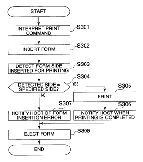
Fig. 3 is a flow chart of a printing process in the printer shown in Fig. 1;
6
CA 02291901 1999-12-07
Fig. 4 is a cross-sectional view of a printer according to a second preferred
embodiment of the present invention;
Fig. 5 is a flow chart of a printing process in the printer shown in Fig. 4;
Fig. 6 is a cross-sectional view of a printer according to a third preferred
embodiment of the present invention;
Fig. 7 is a flow chart of a printing process in the printer shown in Fig. 6;
Fig. 8 is a flow chart of a printing process according to a fourth preferred
embodiment of the present invention;
Fig. 9 is a flow chart of a process performed by a host device during
execution
of the printing process according to a fourth preferred embodiment of the
present
invention;
Fig. 10 is a functional block diagram of a control unit in a printer according
to
a fifth preferred embodiment of the present invention;
Fig. 11 is a flow chart of a printing process according to a fifth preferred
embodiment of the present invention;
Fig. 12 is used to describe an exemplary method according to the present
invention for detecting which side of a print medium is facing a particular
direction;
Fig. 13 is used to describe a further exemplary method according to the
present invention for detecting which side of a print medium is facing a
particular
direction;
Fig. 14 is used to describe an exemplary method according to the present
invention for detecting which side of a print medium is facing a particular
direction
and the direction in which the print medium is inserted;
Fig. 15 is used to describe a further exemplary method according to the
present invention for detecting which side of a print medium is facing a
particular
direction and the direction in which the print medium is inserted;
Fig. 16 is used to describe another exemplary method according to the present
invention for detecting which side of a print medium is facing a particular
direction
and the direction in which the print medium is inserted;
Fig. 17 is a functional block diagram of a control unit in a printer according
to
a sixth preferred embodiment of the present invention;
Fig. 18 is a flow chart of a printing process according to a sixth preferred
embodiment of the present invention; and
7
CA 02291901 1999-12-07
Fig. 19 is a flow chart of a conventional printing process for printing to
both
sides of a standardized form according to the related art.
Description of the Preferred Embodiments
The preferred embodiments of the present invention are described below with
reference to the accompanying figures.
Embodiment 1
Fig. 1 is a cross-sectional view of a printer 10 according to a first
preferred
embodiment of the present invention. This printer 10 comprises a main housing
101
having a control unit, a form insertion opening 102 from which a cut form or
other
print medium is inserted, an MICR reader 103, transportation rollers 104a to
104d,
print head 105 for printing print data to the print medium, a platen 106
opposite the
print head 105, and a form ejection mechanism 107 for passing the print medium
out
from the printer. The MICR reader 103 is disposed in proximity to the form
insertion
opening 102 for reading MICR text preprinted on an inserted print medium.
Fig. 2 is a functional block diagram of a control unit for a printer according
to
this first embodiment of the invention. As shown in Fig. 2 this control unit
200
comprises an input/output (I/O) interface 201, a data receiver 202, a received
data
interpreter 203, an inserted side detection processor 207, a print buffer 206
for
temporarily storing print data for a particular form side, a printing
controller 208 for
printing data stored to the print buffer 206, a data transmitter 205, and a
controller
204 for controlling various parts of the printer 10.
Control commands, print data, and other information are passed between the
control unit 200 and the host 220 through the I/O interface 201. Control
commands,
print data, and other information are received through the I/O interface 201
by the
data receiver 202, and received data is then interpreted by the received data
interpreter 203. The inserted side detection processor 207 determines whether
the
form has been inserted with the front or back side facing a particular
direction. The
data transmitter 205 passes the printer processing status to the host 220 via
the I/O
interface 201.
Fig. 3 is a flow chart of a printing process run by a printer according to
this
first preferred embodiment of the present invention. At the start of this
printing
process the data receiver 202 of the printer 10 receives and interprets data
sent from
the host 220 by way of the I/O interface 201 (step S301). The received data
includes
both a print command specifying a printing process, and print data. The print
command contains information indicative of whether the print data sent after
the
print command is to be printed on the front or back side of the print medium.
It is to
8
CA 02291901 1999-12-07
be noted that a print command indicating that the print data is to be printed
to the
front side of the print medium is hereafter referred to as form front printing
command, and a print command indicating that the print data is to be printed
to the
back side of the print medium is hereafter referred to as form back printing
command. A print medium usable in this printer are also referred to below as
simply
a "form."
When a form is inserted from the form insertion opening 102 (step S302), the
inserted side detection processor 207 detects whether the form has been
inserted
with the form front or form back facing a particular direction (step S303).
To accomplish this front/back detection, the inserted form is advanced by a
form transportation mechanism comprising transportation rollers 104a and 104b
to
a specific position at the MICR reader 103. The MICR reader 103 then attempts
to
scan the MICR text preprinted to a specific location on the form front. If the
MICR
reader 103 successfully reads the text and captures a magnetic waveform, a
signal
representing the magnetic waveform is sent to the inserted side detection
processor
207. The inserted side detection processor 207 detects whether the form front
or back
is facing up based on whether a signal is received from the MICR reader 103.
That is,
if the MICR reader 103 is able to read MICR text and thus capture a magnetic
waveform from the form surface, the form has been inserted with the front
facing up
for printing to the front; if a magnetic waveform cannot be captured, the form
has
been inserted face down with the back facing up for printing to the back.
The controller 204 performs a printing process or error handling process based
on the results supplied from the received data interpreter 203 and the
inserted side
detection processor 207,.
If the form side detected by the inserted side detection processor 207 is the
same as the form side specified by the print command (step S304 returns yes),
print
data is stored to the print buffer 206. The form is also advanced to a
specific position
at the print head 105 by the form transportation mechanism. The printing
controller
208 then drives the print head 105 to print the print data stored in the print
buffer
206 to the form (step S305). When printing is completed the printing
controller 208
sends a printing completed signal to the controller 204. When the controller
204
receives this printing completed signal, it sends a printing completed
notification
from the data transmitter 205 through the I/O interface 201 to the host 220
(step
S306).
If the form side detected by the inserted side detection processor 207 is not
the
same as the form side specified by the print command (step S304 returns no),
the
9
CA 02291901 1999-12-07
controller 204 sends a form insertion error notification from the data
transmitter 205
through the I/O interface 201 to the host 220 (step S307).
The form is then ejected (step S308) and the printing process ends once the
controller 204 sends either the printing completed notification or form
insertion
error notification to the host 220. It is preferable in this case to eject the
form in
different directions depending on whether the form was inserted appropriately
and
was successfully printed, or was incorrectly inserted and was not printed. For
example, if the form was correctly inserted and printed and the printing
process
therefore ended normally, the form is preferably ejected from the form
ejection
mechanism 107. However, if a form insertion error occurred and the form was
not
printed, the form is preferably ejected from the form insertion opening 102.
In this
way the operator can easily determine whether the form was printed and the
printing process normally completed, or whether the form must be reinserted
and
printed.
It is therefore possible by means of a printer according to this first
preferred
embodiment of the present invention to achieve desired printing results
without the
host being aware of the specific printer configuration because the printer can
determine whether the form side specified for printing by the print command
and the
side of the form inserted for printing are the same.
It is also possible to prevent wasting print forms because the printing
process
is not completed when the side of the form inserted for printing does not
match the
side required for printing by the print command.
Embodiment 2
Fig. 4 is a cross-sectional view of a printer according to a second preferred
embodiment of the present invention. It is to be noted that like parts in Fig.
4 and
Fig. 1 are identified by like reference numerals, and further description
thereof is
omitted below. Furthermore, a printer 20 according to this second exemplary
embodiment of the present invention differs from the printer 10 shown in Fig.
1 in
that it comprises a form reversing mechanism 401 for reversing the front and
back
sides of an inserted form.
This form reversing mechanism 401 comprises a form loading path 402 for
advancing an inserted form, form reversing path 403 for withdrawing a form
from
the form reversing mechanism 401, and gates 404 to 406 for opening and closing
the
openings to the form loading path 402 and form reversing path 403. To reverse
a
form, gate 404 is operated to open the entrance to the form loading path 402.
Gate
405 at this time blocks the entrance to form revei~sing path 403. The form is
then
CA 02291901 1999-12-07
temporarily stored all the way inside the form loading path 402, that is, all
the way
to the right as seen in Fig. 4. Gate 405 is then operated to open the entrance
to form
reversing path 403, and gate 406 is operated to open the exit from the form
reversing
path 403. After thus opening gates 405 and 406, the form is ejected through
the form
reversing path 403 from its stored position inside the form loading path 402.
The
front and back sides of the form are thus reversed from the orientation in
which the
form was inserted.
Fig. 5 is a flow chart used to describe an exemplary printing process of the
printer shown in Fig. 4 according to this second embodiment of the invention.
When a form is inserted from the form insertion opening 102 (step S501), the
inserted side detection processor 207 detects whether the form has been
inserted
with the form front or form back facing a particular direction (step S502) as
described above. The controller 204 then sends a form insertion notification
from the
data transmitter 205 through the I/O interface 201 to the host 220 (step
S503). In
response to this notification, the host 220 sends data to the printer 20.
The data sent from the host 220 through the I/O interface 201 is then received
by the data receiver 202 of the printer 20 and interpreted by the received
data
interpreter 203 (step S504). This data typically includes a print command for
accomplishing a printing process, print data, and a form ejection command.
The controller 204 performs a printing process as described below based on
the results supplied from the received data interpreter 203 and the inserted
side
detection processor 207. ,
If the received data interpreter 203 detects a print command in the data
received from the host 220 (step S505 returns yes), print data contained in
the data
received from the host 220 is stored to the print buffer 206.
If the form side detected by the inserted side detection processor 207 is the
same as the form side specified by the print command (step 5506 returns yes),
the
form is advanced to a specific position at the print head 105 by the form
transportation mechanism.
If the form side detected by the inserted side detection processor 207 is not
the
same as the form side specified by the print command (step S506 returns no),
the
form is inverted by the form reversing mechanism 401 (step S507), and then
advanced to a specific position at the print head 105 by the form
transportation
mechanism.
The printing controller 208 then drives the print head 105 to print the print
data stored in the print buffer 206 to the form (step S508). When printing is
11
CA 02291901 1999-12-07
completed the printing controller 208 sends a printing completed signal to the
controller 204. When the controller 204 receives this printing completed
signal, it
sends a printing completed notification from the data transmitter 205 through
the
I/O interface 201 to the host 220 (step S509).
If the received data interpreter 203 detects that a print command is not
received (step S505) and a form ejection command in the data received from the
host
220 (step 5510 returns yes), the form is ejected by the form ejection
mechanism 107
(step S511).
If the received data interpreter 203 does not detect print commands (a print-
front command, print-back command (step 505)), and form ejection command in
the
data received from the host 220 (step 510), the printing process is terminated
because a command for a process other than a printing process was received.
It is therefore possible by means of a printer according to this second
preferred
embodiment of the present invention to prevent wasting print forms, improve
printing e~ciency, and achieve desired printing results without the host being
aware of the specific printer configuration because the printer can determine
whether the form side specified for printing by the print command and the side
of the
form inserted for printing are the same, and if they are not the same can
automatically reverse the form so that the desired side of the form is
presented for
printing and then complete the printing process.
Embodiment 3
Fig. 6 is a cross-sectional view of a printer according to a third preferred
embodiment of the present invention. It is to be noted that like parts in Fig.
6 and
Fig. 1 are identified by like reference numeral, and further description
thereof is
omitted below. Furthermore, a printer 30 according to this second exemplary
embodiment of the present invention differs from the printer 10 shown in Fig.
1 in
that it comprises two printing mechanisms. That is, in addition to print head
105
and platen 106, this printer 30 comprises a print head 601 and platen 602. As
shown
in the figure, print head 105 and print head 601 are disposed on opposite
sides of the
form transportation path.
Fig. 7 is a flow chart used to describe an exemplary printing process of the
printer shown in Fig. 6 according to this third embodiment of the invention.
It is to
be noted that like steps in Fig. 5 and Fig. 7 are identified by like reference
numeral,
and further description thereof is omitted below.
12
CA 02291901 1999-12-07
When a form is inserted and a print command is received (steps S501 to S505)
as described above, the controller 204 performs a printing process as
described
below.
If the form side detected by the inserted side detection processor 207 is the
same as the form side specified by the print command (step S506 returns yes),
the
form is advanced to a specific position at the print head 105 by the form
transportation mechanism. The printing controller 208 then drives the print
head
105 to print the print data stored in the print buffer 206 to the form (step
S701).
If the form side detected by the inserted side detection processor 207 is not
the
same as the form side specified by the print command (step S506 returns no),
the
form is advanced to a specific position at the print head 601. The printing
controller
208 then drives the print head 601 to print the form back print data stored in
the
print buffer 206 to the form (step 5702).
It is therefore possible by means of a printer according to this third
preferred
embodiment of the present invention to prevent wasting print forms, improve
printing efficiency, and achieve desired printing results without the host
being
aware of the specific printer configuration because the printer can
automatically
select which print head to use for the printing process based on which side of
the
form was inserted facing a particular direction.
Embodiment 4
Fig. 8 is a flow chart used to describe an exemplary printing process of a
printer according to a fourth embodiment of the invention. Fig. 9 is a flow
chart of a
process performed by the host. It is to be noted that the control unit and
configuration of a printer 40 according to this fourth embodiment of the
invention
are identical to those of the above-described first embodiment.
When a form is inserted from the form insertion opening 102 of the printer 10
(step S801), the inserted side detection processor 207 detects whether the
form has
been inserted with the form front or form back facing a particular direction
(step
S802) as described above. The controller 204 then notifies the host 220 which
side
was detected by the inserted side detection processor 207 (step S803). That
is, if the
inserted side detection processor 207 detects the front of the form facing up,
the
controller 204 sends a "front" form side notification to the host 220 through
the I/O
interface 201; if the back of the form is detected, the controller 204 sends a
"back"
form side notification to the host 220.
When the host 220 receives a form side notification from the printer 10 (step
S901), it detects whether the notification indicates the front or back side of
the form
13
CA 02291901 1999-12-07
(step S902). If a front side notification is received (step S902 returns
"front"), the
host 220 sends data for printing to the form front to the printer 10 (step
S903).
However, if a back side notification is received (step S902 returns "back"),
the host
220 sends data for printing to the form back to the printer 10 (step S904).
The printer 10 thus appropriately receives print data corresponding to the
front or back side orientation of the inserted form from the host 220 through
the I/O
interface 201 and data receiver 202, and stores the received print data to
print buffer
206 (step 5804). The printing controller 208 then drives the print head 105 to
print
the print data stored to print buffer 206 to the inserted form (step 5805),
and then
ejects the form from the form ejection mechanism 107 (step S806).
It is to be noted that if the form side desired for printing does not match
the
side indicated by the form side notification from the printer, the host can
alternatively send a form ejection command instead of sending print data, and
can
notify the printer of a form insertion error.
It is therefore possible to achieve desired printing results with a printer
and
control method according to this fourth embodiment of the present invention
because
the printer detects and informs the host which side of the inserted form is
facing a
particular direction, and the host then sends print data for printing to the
form front
or back according to the notification received from the printer.
Embodiment 5
Fig. 10 is a block diagram of control unit functions for a printer according
to
this fifth embodiment of the invention. It is to be noted that like parts in
Fig. 2 and
in Fig. 10 are identified by like reference numeral, and further description
thereof is
omitted below. As shown in Fig. 10 a printer 50 according to this fifth
embodiment of
the invention differs from a printer 10 according to the first embodiment
above in
that it comprises a form front print data buffer 1001 and a form back print
data
buffer 1002. This form front print data buffer 1001 stores print data received
from
the host 220 for printing to the front of an inserted form, and the form back
print
data buffer 1002 similarly stores print data for printing to the back of the
form.
Depending on whether the form is inserted with the front or back facing a
particular
direction, the print buffer 206 temporarily stores print data from either the
form
front print data buffer 1001 or form back print data buffer 1002.
Fig. 11 is a flow chart used to describe a printing process of a printer
according
to this fifth embodiment of the invention.
14
CA 02291901 1999-12-07
The printer 50 receives data from the host 220 into the data receiver 202
through the I/O interface 201, and the received data interpreter 203 then
interprets
the received data (step S 1101).
The controller 204 performs a printing process as described below based on
the results supplied from the received data interpreter 203.
If the received data interpreter 203 detects a form front data storage command
(step S 1102 returns to yes), the controller 204 sends a request to the host
220 from
the data transmitter 205 by way of the I/O interface 201 to start sending
data. When
the host receives this sending start request, it begins sending the front data
to the
printer 50. The printer 50 then stores the form front print data received from
the
host 220 through the I/O interface 201 and data receiver 202 to the form front
print
data buffer 1001 (step S 1103).
If the received data interpreter 203 detects a form back data storage command
(step S 1104 returns to yes), the controller 204 sends a request to the host
220 from
the data transmitter 205 by way of the I/O interface 201 to start sending
data. When
the host receives this start sending request, it begins sending the back data
to the
printer 50 . The printer 50 then stores the form back print data received from
the
host 220 through the I/O interface 201 and data receiver 202 to the form back
print
data buffer 1002 (step S 1105).
If the received data interpreter 203 detects a start printing command (step
S 1106 returns to yes), the controller 204 starts a printing process. This
printing
process starts by form insertion (step S 1107) and the inserted side detection
processor 207 detecting whether the form front or back is facing up (step S
1108).
Based on which side of the form is facing the particular direction, that is,
up in this
example, print data is copied from the appropriate form front print data
buffer 1001
or form back print data buffer 1002 to the print buffer 206 (step S 1109).
That is, if the form is inserted with the front facing up in this example, the
controller 204 copies the print data stored to the form front print data
buffer 1001 to
the print buffer 206. If the form is inserted with the back facing up in this
example,
the controller 204 copies the print data stored to the form back print data
buffer 1002
to the print buffer 206.
The printing controller 208 then drives the print head 105 to print the print
data stored in the print buffer 206 to the form (step S1110). When printing is
completed the printing controller 208 sends a printing completed signal to the
controller 204. When the controller 204 receives this printing completed
signal, it
sends a printing completed notification indicative that the inserted side has
been
CA 02291901 1999-12-07
printed from the data transmitter 205 through the I/O interface 201 to the
host 220
(step S 1111). The form is then ejected by the form ejection mechanism 107
(step
S 1112).
It is to be noted that when print data is sent from the host 220 to the
printer
50, the print data can be sent in conjunction with a data storage command. In
this
case the data receiver 202 buffers the print data while the received data
interpreter
203 interprets the data storage command.
It is further possible to send a storage command, start printing command, and
print data simultaneously. In this case the data receiver 202 buffers the
print data
while the received data interpreter 203 interprets the data storage command,
the
received print data is stored to either the form front print data buffer 1001
or form
back print data buffer 1002 , and the start printing command is then executed.
By thus storing form front print data and form back print data in separate
buffers and detecting which side of the inserted form is facing a particular
direction,
a printer according to this fifth embodiment of the present invention can
selectively
print data stored to the buffer corresponding to the particular form side.
Furthermore, by storing print data in the printer, steps for sending data that
is printed repeatedly can be eliminated, and printer throughput and efficiency
can
thus be improved.
It is to be further noted that the preceding embodiments of the present
invention have been described as using MICR text preprinted to a specific
location
on a form and an MICR text reader for detecting the form insertion direction.
The
invention shall obviously not be so limited, however, and MICR text and an
MICR
reader can be respectively replaced with a bar code and bar code reader, for
example:
It is further possible to differentiate form sides based on the shape of the
form
using an exemplary method as described below.
Exemplary methods for detecting a form insertion side based on form share
An exemplary print medium according to the present invention has, for
example, a corner cut off at the top left and bottom right corners of the form
as seen
from the form front or face. These corners can be detected using, for example,
a
photodetector to determine the insertion direction and form side.
In Fig. 12, the inserted side detection processor 207 has a single detector
disposed at position (A), that is, the left edge of the long side of the form
as seen in
Fig. 12. An inserted form advances in the direction of arrow F. As a result,
the
detector (A) detects the form at two points as indicated by the stars in Fig.
12. The
16
CA 02291901 1999-12-07
results of this form edge detection can then be used to detect the front and
back of
the inserted form by referring to a table as shown in Fig. 12.
For example, if the form is inserted from form top T, no form is detected when
leading edge T is advanced to detector position (A), and the form is then
detected
when form bottom B reaches position (A), the form is determined to have been
inserted face up.
Fig. 13 shows an alternative embodiment in which detectors are disposed at
positions (A) and (B), that is, at both right and left long edges of the form.
In this case
an inserted form is detected by detectors at two points (A) and (B). The
results of this
form edge detection can again be used to detect the front and back of the
inserted
form by referring to a table as shown in Fig. 13.
For example, if the form is inserted from form top T, no form is detected at
detector (A) when form top T is advanced to detector position (A) but the form
is
detected at detector (B), the form is determined to have been inserted face
up.
It is also possible using two detectors (A) and (B) to determine which side of
the form is inserted facing a particular direction, and whether the form has
been
inserted with the long or short side of the form leading, that is the
insertion
direction. In this case an inserted form is advanced in the direction of arrow
F and
the form is detected at four points by detectors (A) and (B) as indicated by
the stars
in Fig. 14. The results of this form edge detection can again be used to
detect the
front and back of the inserted form and whether the long or short edge is
leading by
referring to a table as shown in Fig. 14.
For example, if detector (B) returns different results at edges T and B of the
form, the form has been inserted lengthwise to the printer as shown on the
left side
in Fig. 14. However, if detector (B) returns the same result at edges T and B
of the
form, the form has been inserted widthwise to the printer as shown on the
right side
in Fig. 14. The front and back sides of the form can also be detected using
the same
logic used and shown in Fig. 12.
Form detection when the form is notched at only one corner, that is, at the
top
left as seen from the form front, is described next with reference to Fig. 15.
Detectors
are again provided at positions (A) and (B) as in Fig. 13. When a form is
inserted it is
immediately detected at both positions (A) and (B). The results of this
detection can
then be used to detect whether the form has been inserted front or back side
up, or
with the normally trailing bottom edge first. The form front is again viewed
as shown
in Fig. 12 to Fig. 14.
17
CA 02291901 1999-12-07
Fig. 16 shows a further casein which detectors are provided as above at points
(A) and (B) and at an additional point (C) corresponding to the right edge of
a form
when inserted widthwise as shown on the right in Fig. 16. In this case an
inserted
form advanced in the direction of arrow F is detected at six points by
detectors (A),
(B), and (C). In this case it is possible to detect the front and back of an
inserted form,
as well as the top, bottom, right, and left sides of the form. The form front
in this case
is also viewed as shown in Fig. 12 to Fig. 14.
Embodiment 6
Fig. 17 is a block diagram of control unit functions for a printer according
to a
sixth embodiment of the invention. It is to be noted that like parts in this
and the
first embodiment above are identified by like reference numeral, and further
description thereof is omitted below.
As shown in Fig. 17 a printer 60 according to this sixth embodiment of the
invention differs from a printer 10 according to the first embodiment above in
that it
comprises a form front print data buffer 1001 and a form back print data
buffer
1002, and a print data rotation processor 1701. The print data rotation
processor
1701 rotates print data read from the form front print data buffer 1001 or
form back
print data buffer 1002 based on which side of the inserted form is facing a
particular
direction, and which edge of the form is leading. In addition, print data
rotated by
the print data rotation processor 1701 is stored to the print buffer 206 and
printed.
Fig. 18 is a flow chart used to describe an exemplary printing process of the
printer shown in Fig. 17 according to this sixth embodiment of the invention.
It is to
be noted that like steps in Fig. 17 and the above-noted flow charts are
identified by
like reference numeral, and further description thereof is omitted below.
This printer 60 prepares for printing by means of steps S 1101 to S 1106 shown
in Fig. 11. When a form is inserted (step S 1107), the inserted side detection
processor
207 determines whether the form front or back is facing up (step S 1108).
Based on
which side of the form is facing the particular direction, that is, up in this
example,
print data is copied from the appropriate form front print data buffer 1001 or
form
back print data buffer 1002 to the print data rotation processor 1701 (step S
1801).
The controller 204 then obtains the form insertion direction detected by the
inserted side detection processor 207 (see directions a, b, c, and d in Fig.
16).
If the form insertion direction is c (step S 1802), the print data in the
print
data rotation processor 1701 is rotated clockwise 270 degrees (step S1803) and
then
sent to the print buffer 206.
18
CA 02291901 1999-12-07
If the form insertion direction is d (step S 1804), the print data in the
print
data rotation processor 1701 is rotated clockwise 180 degrees (step S 1805)
and then
sent to the print buffer 206.
If the form insertion direction is b (step S 1806), the print data in the
print
data rotation processor 1701 is rotated clockwise 90 degrees (step S 1807) and
then
sent to the print buffer 206.
The print buffer 206 temporarily stores the print data rotated by the print
data rotation processor 1701 (step S 1808). The printing controller 208 then
drives
the print head 105 to print the print data stored in the print buffer 206 to
the form
(step S 1110). When printing is completed the printing controller 208 sends a
printing completed signal to the controller 204. When the controller 204
receives this
printing completed signal, it sends a printing completed notification from the
data
transmitter 205 through the I/O interface 201 to the host 220 (step S 1111).
The
printed form is then ejected by the form ejection mechanism 107 of the printer
60
(step S 1112).
It will also be obvious that while this exemplary embodiment of the invention
is described rotating test 0 degrees, 90 degrees, 180 degrees, or 270 degrees
to
accommodate four directions, text can alternatively be rotated to other
angles.
Furthermore, text can be rotated clockwise as noted above, counterclockwise,
or a
combination of both to desirably shorten the data processing time.
It is therefore possible by means of a printer according to this sixth
embodiment of the present invention to achieve desirable printing results by
storing
form front print data and form back print data in separate buffers, and
rotating the
print data according to the insertion direction and side of the inserted form.
As described above, it is possible by means of a printer, a printer control
method, and a data medium according to the present invention to determine
whether
the side of a form inserted for printing matches the side of the form
specified by a
print command. As a result, desirable printing results can be achieved and
wasting
printing forms as a result of printing to the wrong side of the form can be
prevented.
Printer throughput and e~ciency can therefore be improved.
Furthermore, the host device can easily control the printing process without
the host device being switched or set to match a particular printer
configuration.
Yet further, the printer operator can use the printer without concern for
whether a form is inserted with one side facing a particular direction or
whether the
form is inserted with a particular edge leading through the form
transportation
path.
19
CA 02291901 1999-12-07
Although the present invention has been described in connection with the
preferred embodiments thereof with reference to the accompanying drawings, it
is to
be noted that various changes and modifications will be apparent to those
skilled in
the art. For example, the present invention has been described with reference
to a
printer in which the print head and MICR head are disposed to the same side of
the
form transportation path such that when a form is inserted face or front side
up,
data is printed to the front or face side of the form. It will be obvious,
however, that
the print head and MICR head can be disposed to opposite sides of the form
transportation path such that when a form is inserted face or front side up,
data is
printed to the back or opposite side of the form.
Such changes and modifications are to be understood as included within the
scope of the present invention as defined by the appended claims, unless they
depart
therefrom.