Note: Descriptions are shown in the official language in which they were submitted.
CA 02292071 1999-12-13
1
Method and device for drying a gas.
This invention relates to a method for drying a gas by
means of adsorption on a desiccant able to be
regenerated, according to which method a gas is sent
through a first amount of this desiccant, while a
portion of the dried gas is sent through a second amount
of already used desiccant for regenerating it, this gas
portion for the regeneration being heated and after
having taken up moisture is evacuated, whereby, after
regenerating the second amount of desiccant, the gas
flow is inverted so that the gas to be dried is sent
through the regenerated second amount of desiccant,
while a portion of the dried gas is now sent through the
first amount for regenerating.
Methods of this kind are used amongst others for drying
compressed gas, mostly compressed air. The compressed
gas leaving the compressor has a relatively high
moisture content. Part of the moisture is separated by
cooling this air. The remaining moisture may be
disadvantageous for the conducts and is undesirable for
some applications.
A known method of this kind is disclosed amongst others
in EP-A-0.419.433. The compressed air to be dried is
dried in a first column, while the wet desiccant is
regenerated in a second column by a portion of the dried
compressed air. This portion is introduced, at half-
CA 02292071 1999-12-13
2
height of the column, in the lower end of a tube mounted
axially in the column and containing an electrical
heating element. The gas is heated in the tube and flows
in the wet desiccant at the top of the column, flows
downward and leaves, charged with moisture, the column
at the bottom.
It is evident that this heated gas causes a heating of
the desiccant. Heated desiccant is however less
effective than cold desiccant and therefore the
regenerated desiccant is normally cooled before being
used again for drying. If the desiccant is too hot when
it is used for drying, a regeneration will start instead
of drying. Cooling is also necessary to avoid dew point
pikes during drying.
In said known method, this cooling is obtained by
turning off the electrical heating while a portion of
the dried compressed air is still sent through the
desiccant.
In this way, the cooling can only take place after the
complete regeneration of the desiccant and consequently
the complete regeneration and cooling process is time-
consuming. Moreover, an additional amount of already
dried air is required for the cooling and is lost for
consumption. This increases the energy consumption.
The invention seeks to provide a method for drying a gas
avoiding said disadvantages and permitting to minimalize
the energy consumption for regenerating the desiccant.
CA 02292071 2007-09-19
3
In accordance with the invention, this object is accomplished by a method for
drying a gas by means of adsorption on a desiccant able to be regenerated,
according to which method a gas is sent through a first amount of this
desiccant,
while a portion of the dried gas is sent through a second amount of already
used
desiccant for regenerating it, this gas portion for the regeneration being
heated
and after having taken up moisture is evacuated, whereby, after regenerating
the second amount of desiccant, the gas flow is inverted so that the gas to be
dried is sent through the regenerated second amount of desiccant, while a
portion of the dried gas is now sent through the first amount for
regenerating,
characterized in that the gas portion used for the regeneration is heated in
at
least two successive steps, said steps being performed in different zones
situated successively in the flow direction of the gas portion through the
regenerating desiccant and by stopping the heating in a zone as soon as the
desiccant in this zone is regenerated, so that this zone may already cool down
by the gas portion for regeneration while a successive zone is still
regenerated
by the heated gas.
Other preferred embodiments, aspects, objects, variants and/or advantages of
the present invention are briefly summarized hereinbelow.
Indeed, advantages are obtained by heating the gas portion used for the
regeneration in at least two successive steps, said steps being performed in
different zones situated successively in the flow direction of the gas portion
through the regenerating desiccant and by stopping the heating in a zone as
soon as the desiccant in this zone is regenerated, so that this zone may
already
cool down by the gas portion for regeneration while a successive zone is still
regenerated by the heated gas.
It is obvious that the first zone to be regenerated will
be the zone where the gas portion for regeneration is
entered as this gas portion has not yet taken up much
moisture.
CA 02292071 2007-02-23
3a
This is especially the case if the gas portion for
regeneration is sent through an amount of desiccant in
the opposite direction as the gas to be dried was sent
when this amount was used for drying.
In this case said first zone is the zone which has taken
up the less of moisture during drying.
The number of heating steps and consequently zones
during regeneration may be higher than two.
Heating of the zones of the amount of desiccant which is
regenerated may be performed in several ways, for
CA 02292071 2007-02-23
4
example by electrical heating elements, but a very
effective way of heating is by means of microwaves.
The invention also relates to a device which is
especially suitable for applying the method according to
either one of the preceding embodiments.
The invention concerns consequently a device for drying
gas by adsorption, comprising an inlet pipe for the wet
gas, an outlet pipe for the dried gas and between them at
least two vessels mounted in parallel filled with a
desiccant able to be regenerated, means for connecting
the inlet pipe alternately with the inlet of one of the
vessels and the inlet of the other vessel for drying the
wet gas, means for returning a portion of the dried gas
to the vessel whi ch is not connected to the inlet pipe,
for the regeneration of the desiccant and heating means
in both vessels, said heating means comprising at least
two heating elements which are situated successively in
different zones in the flow direction of the gas through
the vessel and which can be switched in or off
separately, characterized in that the device comprises
means for measuring directly or indirectly the moisture
content in each zone and a control device connected to
said means for commanding the heating elements
individually in function of the moisture contents
measured by said means.
US-U-5.485.686 discloses a drying device with two
vessels filled with desiccant able to be regenerated, a
two heater coils being mounted in each vessel, one above
CA 02292071 1999-12-13
the other. Only the bottom heater coil is switched on in
a vessel when the air is dried therein, for heating the
dried air to the optimal temperature for the use of the
air, this is the drying of thermoplastics. During
5 regeneration of the desiccant in a vessel, both heater
coils are switched on.
According to the invention, preferably, the heating
elements are microwave sources.
The invention will now be described by way of example
and with reference to the accompanying drawings in
which:
Figure 1 shows schematically a compressor installation
possessing a device for drying gas according to the
invention;
Figure 2 shows schematically the device for drying gas
from the installation of figure 1;
Figure 3 shows a part of the device of figure 2, but
on a larger scale and with respect to another
embodiment of the invention;
Figure 4 is a cross-section according to line IV-IV in
figure 3.
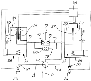
Figure 1 shows a compressor installation which comprises
essentially a compressor 1 and in the compressed air
conduit 2 of it successively an after cooler 3, a
pressure vessel 4, an oil separator 5 and a drying
device formed by an adsorption dryer 6.
CA 02292071 1999-12-13
6
As shown more in detail in figure 2, this adsorption
dryer 6 comprises two columns or upstanding vessels 7
and 8 which are mounted in parallel between the inlet
pipe 9 and an outlet pipe 10 and which are filled with a
desiccant 11, for example silica-gel.
The inlet pipe 9 consists of the portion situated before
the vessels 7 and 8 of the compressed air conduit 2 and
is connected by means of a first pneumatically
controlled three-way valve 12 and one of two conduits 13
and 14 connected thereto, with respectively the vessel 7
or the vessel 8.
The outlet pipe 10 consists of the portion situated
after the vessels 7 and 8 of the compressed air conduit
2 and is connected by means of two conduits 15 and 16
with respectively the vessels 7 and 8.
In the conduit 15 a non-return valve 17 is mounted while
in the conduit 16 a non-return valve 18 is mounted. Both
non-return valves 17 and 18 prevent the gas to return to
the vessel 7 or 8.
In a variant, the two non-return valves 17 and 18 may be
replaced by a single three-way valve.
Both non-return valves 17 and 18 are shunted by a
conduit 19 containing a throttle valve 20.
CA 02292071 2007-02-23
7
To conduits 13 and 14 is connected an air outlet pipe 21
or 22 which can be closed by a pneumatically controlled
valve 23 or 24.
In each of the vessels 7 and 8, heating means are
mounted which each consist of a number, in the given
example two, heating elements distributed over the
height of the vessels in different zones.
Vessel 7 contains thus two heating elements 25and 26,
more particularly electrical resistances, while vessel 8
contains two heating elements 27 and 28, more
particularly electrical resistances.
The uppermost heating elements 25 and 27 are mounted
inside an axially extending tube 29 which is perforated
at the top of the vessel 7 or 8 and which is connected
with its lower end, approximately at half-height of the
vessel 7 or 8, with the conduit 15 or 16.
The tube 29 opens with its perforations on the upper
zone 30 of the vessel 7 or 8.
The heating elements 26 and 28 are situated in the
desiccant 11 in the lower zone 31 of the vessel 7 or 8.
Direct contact of the heating elements 26 and 28 with
the desiccant 11 is preferably avoided, particularly
when these heating elements 26 and 28 are electrical
resistances, in order to prevent hot spots in the
CA 02292071 2007-02-23
8
desiccant. The wire of the resistances may therefore for
example be surrounded with a heat-dissipating material.
The heating elements 25, 26, 27 and 28 may be
individually switched on or off by means of a control
device 34.
Both non-return valves 17 and 18 are shunted together by
a conduit 19 which can be closed by a valve 20 also
controllable by said control device 34.
Said control device 34 also controls the pneumatically
controlled valves 23 and 24 and the three-way valve 12.
The above-mentioned device operates as follows:
The compressed air produced by the compressor 1 is
cooled in the after cooler 3 and accumulated in the
pressure vessel 4 where it is further cooled. As a
result, part of the moisture in the compressed air will
condensate. The condensate is separated in a manner not
shown in the figure 1.
After separation of the oil in the oil separator 5, the
compressed air enters via the inlet pipe 9 in the
adsorption dryer 6.
When the three-way valve 12 is in the position shown in
figure 2, the compressed air enters via the conduit 13
in the vessel 7 where remaining moisture of the air is
adsorbed in the desiccant 11.
CA 02292071 1999-12-13
9
The heating elements 25 and 26 are switched off and the
valve 23 is closed.
The dried air leaves the vessel 7 through the tube 29
and the conduit 15 and reaches through the non-return
valve 17 the outlet pipe 10. The non-return valve 18
prevents the air to enter the conduit 16.
A small portion, for instance 3 to 8 vol. % of the dried
air, however, reaches the conduit 16 through the shunt
conduit 19, as far as the desiccant 11 in vessel 8 has
already been used for drying and is saturated with
moisture.
This portion of the dried air expands in the tube 29 in
the vessel 8. The heating elements 27 and 28 are
switched on by the control device 34 and the valve 24 is
opened.
The air portion is first heated by the heating element
27 up to a temperature between 120 to 250 C, enters the
upper zone 30 and flows downwards through the desiccant
11. This portion of air is further heated by the heating
element 28 in the lower zone 31.
Due to the heated air, the desiccant 11 in the vessel 8
is regenerated. The heating element 28 prevents
condensation of the moisture with which the air portion
has been saturated in the zone 30 and permits taking up
CA 02292071 1999-12-13
of more moisture by the air because of its higher
temperature.
The regenerating air charged with moisture is evacuated
5 through the outlet pipe 22 in which the valve 24 is
open.
The air portion for regenerating will first take up
moisture from top. The dryer the top, the more the air
10 can take up moisture from a lower layer of desiccant 11.
The desiccant 11 in the upper zone 30 will be dry and
thus regenerated before the desiccant 11 in the lower
zone 31.
This is the more the fact that, as during drying with
the desiccant 11, the wet air flows from bottom to top,
the desiccant 11 in the lower zone 31 contains more
moisture than the desiccant 11 in the upper zone 30 when
the regeneration starts.
After a certain time, namely when the desiccant 11 in
the upper zone 30 is expected to be dry, or preferably
after a sensor measuring the degree of moisture in this
zone 30 shows that the desiccant 11 in this zone 30 is
dry, the control device 34 switches off the heating
element 27.
This moisture content may be measured indirectly by
measuring the temperature. When the temperature of the
air at the lower end of zone 30 reaches its maximum
CA 02292071 2007-02-23
11
situated between 150 and 200 C, there is no water to be
taken up from the desiccant 11 in this zone 30.
This means that the air portion for the regeneration
cools the desiccant 11 in the upper zone 30 which was
previously heated, while the air in the lower zone 31 is
still heated by the heating element 28 and still dries
the desiccant 11 in this zone 31.
When also the desiccant 11 in this zone 31 is dry, which
can be detected by measuring the temperature at the
outlet of zone 31, the control device 34 switches off
the heating element 28 and the zone 31 is cooled.
Finally the valve 24 is closed.
When the desiccant 11 in the vessel 7 is no longer
effective and must be regenerated, the control device 34
changes the position of the three-way valve 12 so that
the pipe 9 is now connected with the conduit 14. The
regenerated desiccant 11 in the vessel 8 is now used for
drying, while the desiccant 11 in the vessel 7 is
regenerated in exactly the same manner as described
herebefore for the desiccant 11 in the vessel 8. At the
start of the regeneration, the valve 23 is opened so
that the pressure can be relieved from the vessel 7 and
the regeneration may be performed at ambient pressure.
As at the end of the regeneration, the upper zone 30 is
already cooled while the lower zone 31 is still being
regenerated, the total cooling time of the regenerated
desiccant 11 is shortened.
CA 02292071 2007-02-23
12
This permits to use a smaller quantity of desiccant 11
in each vessel 7 and 8 and a smaller vessel. Moreover,
the radiation heat losses from the regenerating vessel
are smaller and the energy consumption is lower.
It is obvious that the number of zones 30 and 31 and
thus the number of heating elements 25,26 or 27,28 in
each vessel 7 or 8 may be more than two. Also other
heating means than electric heating elements may be used
as well.
In figures 3 and 4 another embodiment of the adsorption
dryer 6 is shown, whereby this dryer 6 only differs from
the above described dryer 6 in that the vessels 7 and 8
are difierent in construction, more precisely in that.
these vessels 7 and 8 are divided in five zones 32, 33,
35, 36 and 37, four of which can be heated individually
by means of a microwave heat source 38, 39, 40 or 41.
Only a part of the dryer 6 comprising the vessel 7 has
been shown, but the vessel 8 is identical.
Each microwave heat source 38 to 41 consists of a
generator 42 mounted on the outside of the vessel 7 and
an antenna 43 extending inside one of the zones 32, 33, 35, 36 to be heated.
The lowermost zone 37 is not provided with heating means.
Each zone 32, 33, 35, 36 contains also a sensor 44 detecting the moisture
content in the zone and connected via the control device 34 with the generator
42 of the microwave heat source 38, 39, 40 or 41 pertaining to this zone.
CA 02292071 2007-02-23
13
The zones 32, 33, 35, 36, 37 are separated from each other by metallic
perforated screens 45 restraining the microwaves emitted by a heat source 38
to
41 within the corresponding zone. The screens 45 are for instance from
stainless steel.
The perforations of the screens 45 have for instance a
diameter of about 1 mm while the desiccant particles are
beads with a diameter between 2 and 5 mm, so that the
screens 45 not only retain the microwaves but also the
desiccant 11.
The screens 45 are conical in order to distribute the
desiccant 11 over the whole diameter of the vessel 7 and
to obtain a filling of the desiccant 11 without pockets.
In order to permit filling and emptying the vessel 7
with desiccant 11, the screens 45 are provided with an
opening 46 at their top, for instance a round opening 46
with a diameter of about 2 cm, and a number of slots 47
at their lower edge, for instance four triangular slots
47.
Moreover, the vessel 7 is provided with two filling
plugs 48 at its top and two emptying plugs 49 at its
bottom.
A purge pipe 50 with a purge air nozzle 51 is connected
to the conduit 15.
The drying device operates in the same way as described
herebefore except that during the regeneration of the
desiccant 11, the heating of the air portion for the
CA 02292071 2007-02-23
14
regeneration takes successively place in four zones 32, 33, 35, 36 by
microwaves, whereby as soon as a sensor 44 detects that the desiccant 11 in
its
zone is dry, the microwave generator 42 heating this zone is shut off.
The zones 32, 33, 35, 36 will successively from top to bottom be dry and
consequently no longer heated but cooled by the air portion for the
regenerating.
Filling with desiccant 11 takes place by opening the filling plugs 48 and
pouring
desiccant 11 in the vessel 7. The desiccant 11 falls through the slots 47 and
the
opening 46 of a screen 45 and fills up each zone 32, 33, 35, 36, 37.
Emptying for replacing the desiccant 11 occurs by
removing the emptying plugs 49, whereby the desiccant 11
falls down through the openings 46 and slots 47.
In the described embodiments, during the regeneration of
the desiccant 11 in a vessel 7 or 8, the gas flows from
top to bottom in this vessel. It is obvious that the
invention is also applicable with an inverted gas flow,
where the gas flows from bottom to top.
CA 02292071 1999-12-13
The heating in the zones will then be stopped
successively from bottom to top. The heating of the
bottom zone will be stopped while the zone above is
still heated
5