Note: Descriptions are shown in the official language in which they were submitted.
CA 02292102 1999-12-13
- SDP230PA
FLUSH SYSTEM FOR INK CHANGE
Technical Field
The present invention relates to the
field of continuous ink jet printing and, more
particularly, to the flushing of one ink from a
fluid system when replacing it with one of a
different color or chemistry.
Background Art
Continuous ink jet printers are a
substantial capital investment for a printing
company. It is therefore desired to maximize the
time available for such a system to print. A
printer may have a variety of printing jobs, each
requiring a different ink. Ink choice may be based
on color, permanence or ease of operation. It is
therefore desirable that the ink in a continuous ink
jet printer may be easily changed, instead of
dedicating a printer to each type of ink.
As ink chemistry, in addition to color,
may be incompatible between inks, it is desirable to
flush the system with a colorless fluid of low
surface tension to remove and dilute the old ink,
then introduce the new ink.
Existing art requires the operator to
perform such tasks as draining the old ink and flush
fluid by inserting a tube into a fitting while
holding a bucket as the tank drains, disposing of
these buckets of waste, and connecting a special
manifold in place of the printhead to properly route
the fluid. The flush fluid is then circulated and
disposed. No provision is made to remove ink
trapped in tubing by sending it directly to waste.
The flush instead works by successive dilutions of
CA 02292102 1999-12-13
- 2 - SDP230PA
the residual ink.
Another option is to attach a flush
system, consisting of tanks of flush fluid, pumps
and a waste tank. This involves extra expense for
the customer in purchasing the flush system, and the
disadvantage of only flushing one fluid system at a
time with the flush system.
It is therefore an object of the present
invention to provide a means of flushing and
changing the ink in a continuous ink jet fluid
system.
It is a further object of the present
invention to have the flushing include the
printhead(s) in a system.
It is yet another object of the present
invention to accomplish the flushing with a minimum
of auxiliary equipment.
Summary of the Invention
These objects are met by the fluid system
flush technique according to the present invention.
In accordance with one aspect of the
present invention, the fluid flush system flushes
residual ink from a fluid system to facilitate an
ink change. The fluid system may be configured with
one or more printheads. In accordance with the
present invention, a common flush system is provided
to serve all printheads in the multiple printhead
configuration. The separate plumbing within each
printhead interface controller (PIC) and printhead
is, therefore, substantially identical.
Other objects and advantages of the
invention will be apparent from the following
description, the accompanying drawing and the
appended claims.
CA 02292102 1999-12-13
SDP230PA
Brief Description of the Drawina
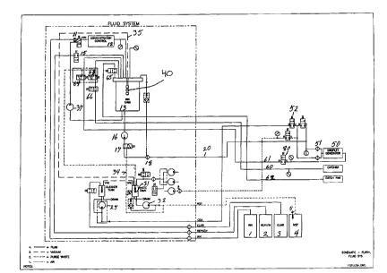
Fig. 1 is a fluid schematic of a fluid
system, with printhead interface controllers and
printheads;
Fig. 2 illustrates the flush fluid supply
connected to both the ink and replenisher fill
ports; and
Fig. 3 illustrates the ink supply
connected to both the ink and replenisher fill
ports.
Detailed Description of the Preferred Embodiments
Referring to Fig. 1, an ink jet print
station comprises an external ink supply tank 1,
connected through a fill solenoid valve 11 and
concentration sensor 12 to ink tank 13. A similar
external replenisher tank 2 is connected to a
replenisher fill valve 15 and through it into the
ink tank. Ink is supplied to the droplet generator
50, by means of a pump 16, through drain valve 17,
filter 18, and printhead ink filter 51. The ink
which is not used for printing returns to the ink
tank via the catcher return line 60, bar outlet line
61, or catch pan line 62. The catcher and bar
outlet lines have solenoid valves 63 and 64 which
can divert the flow to the waste tank 30. Solenoid
valves 65 and 66 serve to start and stop the flow in
the catch pan and catcher lines.
A system flush in accordance with the
present invention comprises the following steps.
Initially, ink is pumped out of ink tank 13 and into
the external waste tank 4 by pump 16, via drain
control valve 17 and waste line 34. As the intent
of this step is to totally drain the ink tank, the
float switch, 40 which during normal operation would
CA 02292102 1999-12-13
- SDP230PA
turn off the ink pump when the ink level is too low,
is disabled. Instead, the ink pump is turned on
until the ink level is below the lowest float
switch, then remains on for a defined time to
totally drain the tank. Catcher and catch pan
valves 66 and 65 are left open, allowing residual
ink to drain into the tank, which is under vacuum.
Prior to pumping out the ink tank, a float switch 5,
in the external waste tank, is checked to ensure
adequate room for the waste ink. This occurs before
every draining of the ink tank. If the tank is
found to be full, the system displays a warning
message to the operator and waits for the tank to be
emptied or replaced.
Either before initiating the flush
sequence or while draining the ink from the ink
tank, the operator must disconnect the refill lines
from the ink supply and replenishment supply
vessels, 1 and 2. These refill lines are teed
together and connected to the flush fluid supply
vessel as shown in Fig.2.
In a second step, the ink tank is refilled
with flush fluid through both the ink and
replenisher fill valves. During the refill with
flush fluid, the float switches in the ink tank are
ignored. As a result, the ink tank refill is
allowed to continue filling until the ink tank
overflows via the vacuum line 35 into internal waste
tank 30. The refilling is finally stopped when the
lowest switch on the float switch assembly 31 of the
internal waste tank 30 is tripped. Overfilling the
ink tank ensures that dried residue on the tank
walls, above the normal fill line, will wet out and
dissolve. In filling the ink tank 13 with flush
fluid, both ink refill and replenishment lines are
CA 02292102 1999-12-13
SDP230PA
used to speed the filling process. Refilling
through the ink refill line alone is quite slow as
the optical concentration sensor assembly 12, as
disclosed and claimed in co-pending, commonly
assigned patent application Serial No. ,
Attorney Docket No. SDP215PA, restricts its flow.
Using both fill lines also ensures that both fill
lines are appropriately flushed.
The third step of the system flush
circulates the flush fluid to the printhead, while
the bar out control valve 64 and catcher 63 waste
valves divert the returning fluid to the internal
waste tank 30. The internal waste tank is pumped
out to the external waste tank 4 as needed by waste
pump 32. The fluid is circulated with the drop
generator in crossflush, returning flush fluid down
the bar outlet line 61 and the catcher line 60. The
fluid is also circulated with ink jets formed by
closing crossflush valve 80, returning flush fluid
down the catcher line when the eyelid is closed or
the catch pan line 62, when the eyelid is open. As
ink residue may accumulate in the crevices of valves
and o-rings, it is desirable to alternate the return
fluid flow through these flow paths to ensure proper
cleaning. The ink tank is refilled as needed, as
controlled by the normal ink tank float switch, with
fresh flush fluid to prevent the tank from emptying
completely. This flushing of the printhead, while
the alternating flush fluid return paths is done for
approximately 3 minutes to remove the bulk of the
ink remaining in the umbilical line 20.
The bar out 64 and catcher 63 waste valves
are then returned to their normal operating
condition. This allows the flush fluid to circulate
back to the ink tank for approximately 2 minutes,
CA 02292102 1999-12-13
- SDP230PA
cleaning the other side of the bar outlet waste
valves. The umbilical heater (not shown) is also
turned on in this state to warm the flush fluid,
aiding in redissolving deposits. While the flush
fluid is circulated to the ink tank, the optical
concentration sensor (OCS) supply pump 37 is turned
on to flush out the OCS supply line and pump.
After this circulation step, the printhead
purge pump 25 and valve 52 are activated to purge
the air filter in the printhead. The filters are
allowed to soak in the purge fluid for a few
seconds, followed by another cycle of purge fluid.
In the next step, the tank is drained as
in step 1, and steps 2 through 6 are then repeated
with clean flush fluid. The number of times the
tank is drained and refilled with the flush fluid
during the flush cycle may vary with the different
ink changeovers. For example, ink with a higher
degree of incompatibility may require more flushes.
Similarly, lighter color inks, such as a yellow ink,
may require additional fill and circulate cycles
with flush fluid to dilute and remove traces of
black ink. On the other hand, a black ink may only
require one cycle of flush fluid as its dark color
masks lighter inks. The number of flush cycles to
employ is normally decided by the controlling
software. The operator may ,however, elect to
repeat the flush cycle if deemed necessary.
Alternatively, during step 5 as described above,
when the flush fluid is circulated through the OCS,
the OCS can monitor the tint or color of the flush
fluid to determine the necessary number of flush
cycles. Typically, two draining and refilling flush
cycles are sufficient. After the appropriate number
of flush cycles are complete, the fluid system ink
CA 02292102 1999-12-13
7 - SDP230PA
filters 18 are replaced with clean filters. The
flush fluid supply is then disconnected from the ink
and replenishment fill lines.
In the final step, both the ink and
replenisher fill ports are connected to the ink
supply tank, as shown in Fig. 3. The system is now
filled with ink and circulated as in steps 3 through
5. The ink fill is controlled by the normal float
switches in the ink tank. The ink is drained and
refilled, and circulated again per steps 3 through
5. The ink is drained from the system, the
replenisher line is connected to the replenisher
fill port, and the system is filled with ink a final
time through the ink fill valve and OCS.
In a preferred embodiment of the present
invention, the flush fluid used is a clear fluid, so
as not to leave residue to tint light colored ink.
It may also have a high pH to be compatible with the
inks used in continuous ink jet systems. The flush
fluid may also contain surfactants to lower the
surface tension to aid in wetting out filters and
other components. Finally, the flush fluid may or
may not be the same as the cleaning fluid used in
shutting down a printhead, such as is disclosed and
claimed in co-pending, commonly assigned patent
application Serial No. , Attorney Docket
No. SDP217PA.
The only additional component used to
perform the flush according to the present invention
is a "tee", as shown in Figs. 2 and 3, to connect
flush fluid or ink supply vessels to both the ink
refill and replenishment fill ports. The pumps and
valves used in the flush perform other uses such as
ink circulation and shutdown cleaning in the fluid
system. The flushing feature does not require
CA 02292102 1999-12-13
SDP230PA
manually draining of the tanks, the use of printhead
simulators, external flush systems or external
vacuum systems. Control of this flushing sequence
is carried out by the fluid system controller which
controls the normal ink jet operation of the fluid
system (not shown):
The invention has been described in detail
with particular reference to certain preferred
embodiments thereof, but it will be understood that
modifications and variations can be effected within
the spirit and scope of the invention. Although
this description has referenced the components for a
single printhead in a multiple printhead fluid
system, it should be understood that the flush
system would concurrently flush the matching
components for the second, or multiple,
printhead(s). The invention is also applicable to
single printhead fluid systems or fluid systems
operating more than one printhead.