Note: Descriptions are shown in the official language in which they were submitted.
CA 02292526 1999-12-03
WO 99/62594 PCTIUS99I10221
PERCUTANEOUS INTRAMUSCUI~AR STIMULATION SYSTEM
Background of the Invention
The present invention relates to the art of
therapeutic neuromuscular stimulation. It finds particular
application for use by human patients who are paralyzed or
partially paralyzed due to cerebrovascular accidents such
as stroke or the like. The invention is useful for
retarding or preventing muscle disuse atrophy, maintaining
extremity range-of-motion, facilitating voluntary motor
function, relaxing spastic muscles, increasing blood flow
to select muscles, and the like.
An estimated 555,000 persons are disabled each
year in the United States of America by cerebrovascular
accidents (CVA) such as stroke. Many of these patients are
left with partial cr complete paralysis of an extremity.
For example, subluxation (incomplete dislocation) of the
shoulder joint is a common occurrence and has been
associated with chronic and debilitating pain among stroke
survivors. In stroke survivors experiencing shoulder pain,
motor recovery is frequently poor and rehabilitation is
impaired. Thus, the patient may not achieve his/her
maximum functional potential and independence. Therefore,
prevention and treatment of subluxation in stroke patients
is a priority.
There is a general acknowledgment by healthcare
professionals of the need for improvement in the prevention
and treatment of shoulder subluxation. Conventional
intervention includes the use of orthotic devices, such as
slings and supports, to immobilize the joint in an attempt
to maintain normal anatomic alignment. The effectiveness
of these orthotic devices varies with the individual.
Also, many authorities consider the use of slings and arm
supports to be controversial or even contraindicated
CA 02292526 1999-12-03
WO 99!62594 PCT/US99/10221
- 2 -
because of the potential complications from immobilization
including disuse atrophy and further disabling
contractures.
Surface, i.e., transcutaneous, electrical
muscular stimulation has been used therapeutically for the
treatment of shoulder subluxation and associated pain, as
well as for other therapeutic uses. Therapeutic
transcutaneous stimulation has not been widely accepted in
general because of stimulation-induced pain and discomfort,
poor muscle selectivity, and difficulty in daily management
of electrodes. In addition to these electrode-related
problems, commercially available stimulators are relatively
bulky, have high energy consumption, and use cumbersome
connecting wires.
In light of the foregoing deficiencies,
transcutaneous stimulation systems are typically limited to
two stimulation output channels. The electrodes mounted on
the surface of the patient' s skin are not able to select
muscles to be stimulated with sufficient particularity and
are not suitable for stimulation of the deeper muscle
tissue of the patient as required for effective therapy.
Any attempt to use greater than two surface electrodes on
a particular region of a patient's body is likely to result
in suboptimal stimulation due to poor muscle selection.
Further, transcutaneous muscle stimulation via surface
electrodes commonly induces pain and discomfort.
Studies suggest that conventional interventions
are not effective in preventing or reducing long term pain
or disability. Therefore, it has been deemed desirable to
develop a percutaneous, i.e., through the skin,
neuromuscular stimulation system that utilizes temporarily
implanted, intramuscular stimulation electrodes connected
by percutaneous electrode leads to an external and portable
pulse generator.
CA 02292526 1999-12-03
WO 99/62594 PCT/US99I10221
- 3 -
Summary of the Invention
In accordance with a first aspect of the present
invention, a percutaneous, intramuscular stimulation system
for therapeutic electrical stimulation of select muscles of
a patient includes a plurality of intramuscular stimulation
electrodes for implantation directly into selected muscles
of a patient and an external battery-operated,
microprocessor-based stimulation pulse train generator for
generating select electrical stimulation pulse train
signals. A plurality of insulated electrode leads are used
for percutaneously interconnecting the plurality of
intramuscular stimulation electrodes to the external
stimulation pulse train generator, respectively. The
external pulse train generator includes a plurality of
electrical stimulation pulse train output channels
connected respectively to the plurality of percutaneous
electrode leads and input means for operator selection of
stimulation pulse train parameters for each of the
stimulation pulse train output channels independently of
the other channels. The stimulation pulse train parameters
include at least pulse amplitude and pulse width or
duration for stimulation pulses of the stimulation pulse
train, and an interpulse interval between successive pulses
of the stimulation pulse train defining a pulse frequency.
Visual output means provides visual output data to an
operator of the pulse train generator. The visual output
data includes at least the stimulation pulse train
parameters for each of the stimulation pulse train output
channels. Non-volatile memory means stores the stimulation
pulse train parameters for each of the plurality of
stimulation pulse train output channels. The generator
includes means for generating stimulation pulse train
signals with the selected pulse train parameters on each of
the plurality of stimulation pulse train output channels so
CA 02292526 1999-12-03
WO 99162594 PCT/US99/10221
- 4 -
that stimulus pulses of the pulse train signals having the
select stimulation pulse train parameters pass between the
intramuscular electrodes respectively connected to the
stimulation pulse train output channels and a reference
electrode.
In accordance with another aspect of the
invention, a method of stimulating select muscle tissue of
a patient includes programming a patient external
stimulation pulse generator with at least one stimulation
pulse train session including at least one stimulation
cycle defining a stimulation pulse train envelope for a
plurality of stimulation pulse train output channels. Each
envelope is defined by at least a ramp-up phase of a first
select duration wherein pulses of a stimulus pulse train
progressively increase in charge, a hold phase of a second
select duration wherein pulses of the stimulus pulse train
are substantially constant charge, and a ramp-down phase of
a third select duration wherein pulses of the stimulus
pulse train progressively decrease in charge. A plurality
of intramuscular electrodes are implanted into select
muscle tissue of the patient and electrically connected to
the plurality of output channels, respectively, of the
pulse train generator. On each of said plurality of
stimulation output channels and in accordance with a
respective envelope, stimulation pulse train signals are
generated with the generator so that the select muscle
tissue of the patient is stimulated in accordance with the
at least one stimulation cycle.
One advantage of the present invention is the
provision of a therapeutic percutaneous intramuscular
stimulation system that retards or prevents muscle disuse
atrophy, maintains muscle range-of-motion, facilitates
voluntary motor function, relaxes spastic muscles, and
increases blood flow in selected muscles.
*rB
CA 02292526 1999-12-03
WO 99162594 PCTIUS99/10221
- 5 -
Another advantage of the present invention is
that it provides a therapeutic muscular stimulation system
that uses intramuscular, rather than skin surface
(transcutaneous) electrodes to effect muscle stimulation of
select patient muscles.
Another advantage of the present invention is
that it provides a small, lightweight, and portable
battery-operated external pulse generator.
A further advantage of the present invention is
that it avoids the use of skin surface electrodes which are
inconvenient, not sufficiently selective to stimulate only
particular muscles, require daily application by the
patient, are subject to patient misapplication, and that
have been found to cause pain or discomfort upon muscle
stimulation.
Still another advantage of the present invention
resides in the provision of a therapeutic stimulation
system that allows for precise muscle selection through use
of intramuscular electrodes, including stimulation of deep
muscles not readily stimulated via transcutaneous
stimulation techniques and associated surface mounted
electrodes.
Yet another advantage of the present invention is
that it is "user-friendly," allowing selective variation of
system operational parameters by a therapist or patient
without the need for any external programming apparatus
such as a personal computer or the like.
A further advantage of the present invention is
the provision of a percutaneous stimulation system with low
power consumption, long battery life (e. g., up to 50 hours
of use) .
A still further advantage of the present
invention is the provision of a percutaneous, intramuscular
stimulation system including a "hot-button" for selective
CA 02292526 1999-12-03
PCTIUS99/10221
WO 99/62594 _ -
- 6 -
instantaneous pulse train generation during system setup to
facilitate adjustment of stimulation pulse train parameters
during system setup.
A yet further advantage of the present invention
is found in a percutaneous intramuscular stimulation system
which logs patient usage for subsequent review by a doctor
or therapist to ensure patient compliance with prescribed
therapeutic stimulation routines.
The foregoing advantages and others will increase
patient acceptance, reduce the service time required from
clinicians, and prevent secondary patient injury requiring
additional medical treatment.
Still further benefits and advantages of the
present invention will become apparent to those of ordinary
skill in the art upon reading and understanding the
following detailed description of the preferred
embodiments.
Brief Description of the Drawincrs
The invention may take form in various components
and arrangements of components, and in various steps and
arrangements of steps. The drawings are only for purposes
of illustrating preferred embodiments, and are not to be
construed as limiting the invention.
FIGURE lA is a front elevational view of a
portable, programmable stimulation pulse train generator in
accordance with the present invention;
FIGURES 1B - 1D are top, bottom, and right-side
elevational views of the stimulation pulse train generator
of FIGURE lA;
FIGURE 2 illustrates a preferred intramuscular
electrode and percutaneous electrode lead;
FIGURE 3 diagrammatically illustrates the
structure and operation of the percutaneous intramuscular
CA 02292526 1999-12-03
PCTIUS99~10221
WO 99/.62594 . J
stimulation system in accordance with the present
invention;
FIGURE 3A diagrammatically illustrates a
preferred pulse amplitude/duration controller, current
driver, and impedance detector circuit in accordance with
the present invention; and,
FIGURE 4 graphically illustrates the stimulation
paradigm of the percutaneous intramuscular stimulation
system in accordance with the present invention.
Detailed Description of the Preferred Embodiments
With reference to FIGURES lA-1D, the
percutaneous, intramuscular stimulation system in
accordance with the present invention includes an
electrical stimulation pulse generator 10. The pulse
generator 10 includes a lightweight, durable plastic
housing 12 fabricated from a suitable plastic or the like.
The case 12 includes a clip 14 that allows the pulse
generator 10 to be releasably connected to a patient's
belt, other clothing, or any other convenient location.
The case 12 also includes a releasable battery access cover
16.
For output of visual data to a patient or
clinician operating the stimulation system, a visual
display 20 is provided. The display 20 is preferably
provided by a liquid crystal display, but any other
suitable display means may alternatively be used. An audio
output device, such as a beeper 22 is also provided.
For user control, adjustment, and selection of
operational parameters, the stimulation pulse generator 10
includes means for input of data. Preferably, the pulse
generator 10 includes an increment switch 24, a decrement
switch 26, and a select or "enter" switch 28. The
increment and decrement switches 24, 26 are used to cycle
CA 02292526 1999-12-03
WO 99/62594 PCT/US99/10221
- 8 -
through operational modes or patterns and stimulation
parameters displayed on the display 20, while the select
switch 28 is used to select a particular displayed
operational pattern or stimulation parameter. The select
switch 28 also acts as a power on/off toggle switch. By
choosing the appropriate mode, the select switch 28 can be
selectively armed as a ~~hot button." During adjustment of
stimulation pulse train parameters, a clinician is able to
activate the hot button to test, instantaneously, the
effect of the selected stimulation pulse train parameters
on the patient's muscles. This facilitates the quick and
proper adjustment of the stimulation pulse train parameters
without requiring the clinician to exit the setup procedure
menu of the stimulation pulse generator 10.
For output of electrical stimulation pulse train
signals, the pulse train generator 10 includes an external
connection socket 30 that mates with a connector of an
electrode cable assembly (not shown) to interconnect the
pulse generator 10 with a plurality of intramuscular
electrodes via percutaneous electrode leads. More
particularly, the cable assembly connected to the socket 30
includes a second connector on a distal end that mates with
a connector attached to the proximal end of each of the
percutaneous stimulation electrode leads and a reference
electrode lead.
A preferred intramuscular electrode and
percutaneous Lead are shown in FIGURE 2. The electrode
lead 40 is fabricated from a 7-strand stainless steel wire
insulated with a biocompatible polymer. Each individual
wire strand has a diameter of 34 ~cm and the insulated
mufti-strand lead wire has a diameter of 250 ~.m. The
insulated wire is formed into a spiral or helix as has been
found preferred to accommodate high dynamic stress upon
muscle flexion and extension, while simultaneously
*rB
CA 02292526 1999-12-03
PCTIUS99110221
WO 99/_62594 .-
- 9 -
retaining low susceptibility to fatigue. The outer
diameter of the helically formed electrode lead 40 is
approximately 580 ~m and it may be encased or filled with
silicone or the like.
As mentioned above, a proximal end 44 of each of
the plurality of intramuscular electrode lead wires 40 is
located exterior to the patient's body when in use. The
proximal end 44 includes a deinsulated length for
connection to an electrical connector in combination with
the remainder of the electrode leads. The distal end 46 of
each lead 40, which is inserted directly into muscle
tissue, also includes a deinsulated length which acts as
the stimulation electrode 50. It is preferred that at
least a portion of the deinsulated length be bent or
otherwise deformed into a barb 48 to anchor the electrode
in the selected muscle tissue. A taper 52, made from
silicone adhesive or the like, is formed between the
deinsulated distal end 50 and the insulated portion of the
lead 40 to reduce stress concentration.
Unlike surface electrodes which are applied to
the surface of the patient's skin using an adhesive, each
of the plurality of percutaneous electrodes 50 is
surgically implanted into select patient muscle tissue, and
the associated electrode lead 40 exits the patient
percutaneously, i.e., through the skin, for connection to
the stimulation pulse generator 10. Preferably, each of
the electrodes 50 is implanted into the select muscles by
use of a hypodermic needle. Once all of the electrodes are
implanted as desired, their proximal ends are crimped into
a common connector that mates with the cable assembly which
is, in turn, connected to the pulse generator 10 through
the connection socket 30.
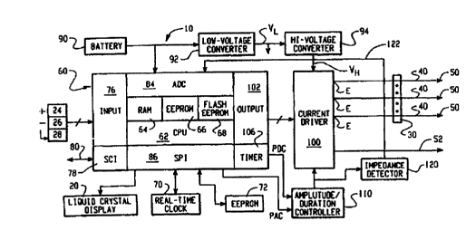
FIGURE 3 diagrammatically illustrates the overall
percutaneous, intramuscular stimulation system in
CA 02292526 1999-12-03
WO 99/62594 PC'TIUS99110221
- 10 -
accordance with the present invention. Unlike surface
stimulation systems which exhibit poor muscle selectivity
and are, thus, typically limited to two stimulation
electrodes and channels, the present percutaneous,
intramuscular stimulation system allows for precise muscle
selection and use of three or more stimulation electrodes
and channels. The preferred system in accordance with the
present invention uses up to eight or more intramuscular
electrodes 50, each connected to an independent electrode
stimulation channel E, and a single reference electrode 52
which may be either an intramuscular or surface electrode.
Those of ordinary skill in the art will also recognize that
the use of intramuscular electrodes allows for selection
and stimulation of deep muscle tissue not practicable by
surface stimulation.
The stimulation pulse generator to comprises a
microprocessor-based stimulation pulse generator circuit
60. The preferred microcontroller is a Motorola 68HC12,
although other suitable microcontrollers may be used
without departing from the scope and intent of the
invention. The circuit 60 comprises a central processing
unit (CPU) 62 for performing all necessary operations.
Random access memory (RAM) 64 is present for temporary
storage of operational data as needed by the CPU 62. A
first nonvolatile memory means, such as electrically
erasable programmable read only memory (EEPROM) 66,
provides nonvolatile storage as needed for operational
instructions or other information, although the first
nonvolatile memory means may not necessarily be used.
Preferably, flash EPROM 68 (rather than write-once EPROM)
is provided for storage of software operating instructions.
Use of flash EPROM 68 facilitates periodic, unlimited
upgrade of the software operating instructions.
In order to log or record patient usage of the
CA 02292526 1999-12-03
PCTIUS99/10221
WO 99/62594 - -
- 11 -
stimulation pulse generator 10, the stimulation circuit 60
includes a real-time clock 70 along with a second
nonvolatile memory means such as EEPROM 72 to provide
sufficient nonvolatile storage for recording and time-
s stamping a patient's use of the system. A clinician is
thereafter able to access the EEPROM 72 to review the
patient's use of the system to ensure patient compliance
with the prescribed therapeutic stimulation protocol.
Preferably, the second nonvolatile memory 72 also provides
storage for all patient-specific stimulation protocols.
The increment, decrement, and select user input
switches 24,26,28 are operatively connected into the
circuit 60 via an input stage 76. In addition, a serial
communication interface (SCI) 78 provides means for
selectively connecting an external device, such as a
computer, as needed by way of an RS-232 connection 80 or
the like for data upload and download. An analog-to-
digital converter 84 performs all analog-to-digital
conversion of data as needed for processing in the circuit
60. A serial peripheral interface (SPI) 86 provides means
for connecting peripheral components, such as the display
20, the clock 70, the EEPROM 72, and other components to
the microcontroller.
Electrical potential or energy is supplied to the
circuit 60 by a battery 90, preferably AA in size and
ranging from 1.0 - 1.6 volts. A low-voltage dc-do
converter 92 adjusts the voltage supplied by the battery 90
to a select level VL, preferably 3.3 volts. To minimize
depletion of the battery during periods of inactivity of
the pulse generator 10, the circuit 60 is programmed to
automatically power-down after a select duration of
inactivity. Those skilled in the art will recognize that
the RAM 64 provides volatile storage, and the storage means
66,68,72 provide nonvolatile storage to prevent loss of
CA 02292526 1999-12-03
PCT/US99/10221
WO 99./62594 , - -
- 12 -
data upon interruption of power to the circuit 60 through
malfunction, battery depletion, or the like.
The output VL of the low-voltage dc-do converter
92 is also supplied to a high-voltage dc-do converter 94
which steps-up the voltage to at least 30 volts. The high
voltage output VH of the dc-do converter 94 provides the
electrical potential for the stimulation pulse train
signals transmitted to the plurality of intramuscular
electrodes 50 through a current driver 100. More
particularly, an output means 102 of the circuit 60
provides channel selection input to the current driver 100
to control the transmission of the high-voltage electrical
potential from the driver 100 to the selected electrodes 50
on a selected one of the plurality of stimulation output
channels E. Although only three output channels E are
illustrated, those skilled in the art will recognize that
a greater number of output channels may be provided.
Preferably, eight output channels E are provided.
The electrical current passes between the
selected electrodes 50 and the reference electrode 52. A
pulse duration timer 106 provides timing input PDC as
determined by the CPU 62 to the pulse amplitude/duration
controller 110 to control the duration of each stimulation
pulse. Likewise, the CPU 62 provides a pulse amplitude
control signal PAC to the circuit 110 by way of the serial
peripheral interface 86 to control the amplitude of each
stimulation pulse. One suitable circuit means for output
of stimulation pulses as described above is in accordance
with that described in U.S. Patent 5,167,229, the
disclosure of which is hereby expressly incorporated by
reference.
In order to ensure that an electrode lead is
properly transmitting the stimulationipulse train signals
to the select muscle tissue, an impedance detection circuit
CA 02292526 1999-12-03
PCTNS99110221
WO 99162594 .-
- 13 -
120 monitors the impedance of each electrode lead 40. The
impedance detection circuit 120 provides an analog
impedance feedback signal 122 to the analog-to-digital
converter 84 where it is converted into digital data for
input to the CPU 62. Upon breakage of a lead 40 or other
malfunction, the impedance detection circuit detects a
change in impedance, and correspondingly changes the
impedance feedback signal 122. The impedance feedback
signal 122 allows the microcontroller to interrupt
stimulation and/or generate and error signal to a patient
or clinician.
FIGURE 3A is a somewhat simplified diagrammatic
illustration of a most preferred current driver circuit
100, pulse amplitude/duration control circuit 110, and
impedance detection circuit 120. The illustrated current
driver circuit 100 implements eight output channels E1-E8,
each of which is connected to an electrode 50 implanted in
muscle tissue for passing electrical current through the
muscle tissue in conjunction with the reference electrode
52. Accordingly, the patient muscle tissue and implanted
electrodes 50 are illustrated as a load RL connected to each
channel E1-E8.
Each output channel E1-E8 includes independent
electrical charge storage means such as a capacitor SC
which is charged to the high voltage V" through a respective
current limiting diode CD. To generate a stimulation
pulse, the microcontroller output circuit 102 provides
channel select input data to switch means SW, such as an
integrated circuit analog switch component, as to the
particular channel E1-ES on which the pulse is to be
passed. Switch means SW closes the selected switch SW1-SWg
accordingly. The microcontroller also provides a pulse
amplitude control signal PAC into a voltage-controlled
current source VCCS. The pulse amplitude control signal
CA 02292526 1999-12-03
PCT/US99/10221
WO 99/62594 _ - -
- 14 -
PAC is converted into an analog signal at 130 by the
digital-to-analog converter DAC. The analog signal at 130
is supplied to an operational amplifier 136 which, in
conjunction with the transistor T1, provides a constant
current output I from the voltage-controlled current source
VCCS. Of course, those of ordinary skill in the art will
recognize that the particular magnitude of the constant
current I is varied depending upon the magnitude of the
voltage signal at 130 input to the OP-AMP 136, i.e., the
circuit VCCS is provided such that the voltage at point 132
seeks the magnitude of the voltage at point 130. As such,
the pulse amplitude control signal PAC controls the
magnitude of the current I, and the circuit VCCS ensures
that the current I is constant at that select level as
dictated by the pulse amplitude control input PAC. For
stimulation of human muscle, it is preferable that the
current I be within an approximate range of 1mA -20mA.
Upon closing one of switches SWI-SWe, the relevant
capacitor SC discharges and induces the current I as
controlled by the pulse amplitude control signal PAC and a
pulse duration control signal PDC. The constant current I
passes between the reference electrode 52 and the relevant
one of the electrodes 50 to provide a cathodic pulse phase
Q~ (see FIGURE 4). The pulse duration PD of the phase Q~ is
controlled by the microcontroller through a pulse duration
control signal PDC output by the timer circuit 106 into the
pulse amplitude/duration control circuit 110. In
particular, the pulse duration control signal PDC is input
to a shut-down input of the OP-AMP 136 to selectively
enable or blank the output of the OP-AMP 136 as desired,
and, thus, allow or stop the flow of current I between the
electrodes 50,52.
Upon completion of the cathodic phase Q~ as
controlled by the pulse duration control signal PDC, the
CA 02292526 1999-12-03
PCTIUS99/10221
WO 99!62594
_ 15 _ _
discharged capacitor SC recharges upon opening of the
formerly closed one of the switches SWl-Swe . The f low of
recharging current to the capacitor SC results in a reverse
current flow between the relevant electrode 50 and the
reference electrode 52, thus defining an anodic pulse phase
Qa. The current amplitude in the anodic pulse phase Qa is
limited, preferably to 0.5mA, by the current limiting
diodes CD. Of course, the duration of the anodic phase is
determined by the charging time of the capacitor SC, and
current flow is blocked upon the capacitor becoming fully
charged. zt should be recognized that the interval between
successive pulses or pulse frequency PF is controlled by
the CPU 62 directly through output of the channel select,
pulse amplitude, and pulse duration control signals as
described at a desired frequency PF.
The impedance detection circuit 120 "detects" the
voltage on the active channel EI-E8 (i.e., the channel on
which a pulse is being passed) through implementation of a
high-impedance voltage follower circuit VF using a
transistor T2. Accordingly, it will be recognized that the
voltage at points 122 and 124 will move together.
Accordingly, for example, in the event of breakage of an
electrode lead 40, a drop in voltage at point 124 will
cause a corresponding drop in voltage at point 122. The
voltage signal at point 122 is fed back to the
microcontroller analog-to-digital converter 84 for
interpretation by the CPU 62 in accordance with stored
expected values indicating preferred impedance ranges. At
the same time, the CPU 62 knows which switch SW1-SWs is
closed. Therefore, the CPU 62 is able to determine the
channel E1-E8 on which the lead breakage occurred.
The preferred stimulus pulse train paradigm is
graphically illustrated in FIGURE 4. A preferred design
implements up to 4 independent preprogrammed patterns. For
CA 02292526 1999-12-03
PCT/US99110Z21
WO 991.62594 _ -
- 16 -
each pattern, a stimulation session S is pre-programmed
into the stimulator circuit 60 by a clinician through use
of the input means 24,26,28. Each session S has a maximum
session duration of approximately 9 hours, and a session
starting delay D. The maximum session starting delay D is
approximately 1 hour. The session starting delay D allows
a patient to select automatic stimulation session start at
some future time. Within each session S, a plurality of
stimulation cycles C are programmed for stimulation of
selected muscles. Preferably, each stimulation cycle
ranges from 2 - 100 seconds in duration.
With continuing reference to FIGURE 4, a stimulus
pulse train T includes a plurality of successive stimulus
pulses P. As is described above and in the aforementioned
U.S. Patent 5,167,229, each stimulus pulse P is current-
regulated and biphasic, i.e., comprises a cathodic charge
phase Q~ and an anodic charge phase Q a. The magnitude of
the cathodic charge phase Q~ is equal to the magnitude of
the anodic charge phase Qa. The current-regulated, biphasic
pulses P provide for consistent muscle recruitment along
with minimal tissue damage and electrode corrosion.
Each pulse P is defined by an adjustable pulse
amplitude PA and an adjustable pulse duration PD. The
pulse frequency PF is also adjustable. Further, the pulse
amplitude PA, pulse duration PD, and pulse frequency PF are
independently adjustable for each stimulation channel E.
The amplitude of the anodic charge phase Qa is preferably
fixed at 0.5 mA, but may be adjusted if desired.
Pulse "tamping" is used at the beginning and end
of each stimulation pulse train T to generate smooth muscle
contraction. Ramping is defined herein as the gradual
change in cathodic pulse charge magnitude by varying at
least one of the pulse amplitude PA and pulse duration PD.
In FIGURE 4, the preferred tamping configuration is
CA 02292526 1999-12-03
PCT/US99/10221
WO 99162594 _ _
- 17 -
illustrated in greater detail. As mentioned, each of the
plurality of stimulation leads/electrodes 40,50 is
connected to the pulse generator circuit 60 via a
stimulation pulse channel E. As illustrated in FIGURE 4,
eight stimulation pulse channels E1,E2,E8 are provided to
independently drive up to eight intramuscular electrodes
50. Stimulation pulse trains transmitted on each channel
E1-E8 are transmitted within or in accordance with a
stimulation pulse train envelope B1-B8, respectively. The
characteristics of each envelope B1-B8 are independently
adjustable by a clinician for each channel E1-E8.
Referring particularly to the envelope B2 for the channel
E2, each envelope B1-B8 is defined by a delay or "off"
phase PDo where no pulses are delivered to the electrode
connected to the subject channel, i.e., the pulses have a
pulse duration PD of 0. Thereafter, according to the
parameters programmed into the circuit 60 by a clinician,
the pulse duration PD of each pulse P is increased or
"tamped-up" over time during a "ramp-up" phase PD1 from a
minimum initial value (e. g., 5 ~csec) to a programmed
maximum value. In a pulse duration "hold" phase PDZ, the
pulse duration PD remains constant at the maximum
programmed value. Finally, during a pulse duration"ramp-
down" phase PD3, the pulse duration PD of each pulse P is
decreased over time to lessen the charge delivered to the
electrode 50.
This "tamping up" and "tamping down" is
illustrated even further with reference to the stimulation
pulse train T which is provided in correspondence with the
envelope B8 of the channel E8. In accordance with the
envelope B8, the pulses P of the pulse train T first
gradually increase in pulse duration PD, then maintain the
maximum pulse duration PD for a select duration, and
finally gradually decrease in pulse duration PD.
CA 02292526 1999-12-03
WO 99/62594 PCT/US99/10221
- 18 -
As mentioned, the pulse amplitude PA, pulse
duration PD, pulse frequency PF, and envelope B1-B8 are
user-adjustable for every stimulation channel E,
independently of the other channels. Preferably, the
stimulation pulse generator circuit 60 is pre-programmed
with up to four stimulation patterns which will allow a
patient to select the prescribed one of the patterns as
required during therapy.
Most preferably, the pulse generator 10 includes
at least up to eight stimulation pulse channels E. The
stimulation pulse trains T of each channel E are
sequentially or substantially simultaneously transmitted to
their respective electrodes 50. The pulse frequency PF is
preferably adjustable within the range of approximately 5Hz
to approximately 50Hz; the cathodic amplitude PA is
preferably adjustable within the range of approximately 1mA
to approximately 20mA; and, the pulse duration PD is
preferably adjustable in the range of approximately 5 ~usec
to approximately 200~CSec, for a maximum of approximately
250 pulses per second delivered by the circuit 60.
The invention has been described with reference
to the preferred embodiments. Obviously, modifications and
alterations will occur to others upon reading and
understanding the preceding detailed description. It is
intended that the invention be construed as including all
such modifications and alterations insofar as they come
within the scope of the appended claims or the equivalents
thereof.