Note: Descriptions are shown in the official language in which they were submitted.
CA 02292936 1999-12-22
ATTORNEY DOCKET NO. 98-2-831
PAGE 2 OF 27
_2_
ANGLED LAMP SOCKET
CROSS-REFERENCE TO RELATED APPLICATIONS
S.N.: 09/149,415, filed 09/08/98, and assigned to the assignee of the
present invention, contains related subject matter and is hereby
incorporated by reference.
TECHNICAL FIELD
The present invention relates to a lamp socket, and more particularly to
an angled lamp socket for a wedge base lamp used in a lighting module
of a motor vehicle wherein the longitudinal axis of the lamp extends in a
first direction and the terminals of the lamp socket generally extend in a
second direction that is at an angle relative to the first direction. For
example, the angled lamp socket of the present invention is particularly
useful in front and rear automobile directional and safety lighting
applications.
BACKGROUND ART
The need for a lamp socket wherein the axis of the horizontal axis of the
lamp inserted therein extends in one direction and the terminals of the
lamp socket extend in another direction at an angle thereto is well
known. Such a lamp socket is herein referred to as an angled lamp
2 5 socket. One such angled lamp socket is referred to in the lamp industry
as a right angle lamp socket. In such a lamp socket, the horizontal axis
of the lamp and the terminals of the lamp socket are oriented at 90°
relative to each other.
3 0 It is presently known to provide an angled lamp socket that is
satisfactory for use in motor vehicle applications. Examples of such
angled lamp sockets are illustrated in U.S. patent nos. 5,197,187 and
CA 02292936 1999-12-22
ATTORNEY DOCKET NO. 98-2-831
PAGE 3 OF 27
-3
5,411,407 (these patents are commonly owned with the instant
application and are incorporated herein by reference). However, such
lamp sockets have a profile height that may be greater than is often
desired. For example, one known angled lamp socket is fabricated by
welding the contacts that engage the leads of the lamp, to the socket
terminals on the opposite or bottom side of the socket. Subsequent to
welding, a sealant is provided to protect the electrical connections within
the lamp socket from environmental considerations. A cover is placed
over the weld and the sealant to improve the appearance of the lamp
socket. However, the use of this additional part increases the profile
height of the lamp socket and adds to the cost of fabrication thereof. In
addition, the welding of the contacts to the terminals in such known lamp
sockets has been limited to a conventional welding process wherein the
welding is effected from the bottom and externally of the lamp socket.
Heretofore, resistance welding has not been feasible within such lamps.
DISCLOSURE OF THE INVENTION
It is an object of the invention to obviate the disadvantages of the prior
2 0 art.
It is an object of the present invention to provide an improved angled
lamp socket.
2 5 It is another object of the present invention to provide an angled lamp
socket that is less costly to fabricate than those heretofore provided.
Another object of the present invention is to provide an angled lamp
socket that eliminates the need for the conventional cover typically used
3 0 to enclose the contact/terminal weld within the lamp socket.
Yet another object of the present invention is to provide an angled lamp
CA 02292936 1999-12-22
-4-
ATTORNEY DOCKET NO. 98-2-831
PAGE 4 OF 27
socket wherein the contacts and terminals thereof are welded together at
an area facing the top side of the lamp socket.
A further object of the present invention is to provide an angled lamp
socket wherein the contacts and terminals thereof may be welded
together within the lamp socket.
Another object of the present invention is to provide an angled lamp
socket wherein the contacts and terminals thereof may be welded
together by resistance welding, if desired.
It is a further object of the present invention to provide an angled lamp
socket having improved life expectancy.
Yet another object of the present invention is to provide an improved
method for assembling the angled lamp socket of the present invention.
This invention achieves these and other objects by providing an angled
lamp socket that comprises a body having a housing attached thereto. At
2 0 least one lamp retaining member is provided within the body and is
structured and arranged to retain a lamp, having a longitudinal lamp axis,
such that the lamp axis will extend in a first direction when the lamp is
inserted into the body. A plurality of lamp contact members is provided
at least a portion of each of that is in the body. Each lamp contact
2 5 member includes a contact lead that comprises a contact lead surface. A
plurality of terminal members is provided at least a portion of each of
that is in the housing. Each terminal member comprises a terminal lead
surface that engages a respective contact lead surface in the housing.
Each terminal generally extends in a second direction, such second
3 0 direction being at an angle to the first direction. Each respective
contact
lead surface is electrically connected to a respective terminal lead surface
by (a) a weld at an interface of each respective contact lead surface and a
CA 02292936 1999-12-22
ATTORNEY DOCKET NO. 98-2-831
PAGE 5 OF 27
-5-
respective terminal lead surface, such weld facing the front end of the
body, or (b) a spring biased engagement at an interface of each
respective contact lead surface and a respective terminal lead surface. A
method for assembling an angled lamp socket is also provided.
BRIEF DESCRIPTION OF THE DRAWINGS
This invention may be clearly understood by reference to the attached
drawings in that like reference numerals designate like parts and in that:
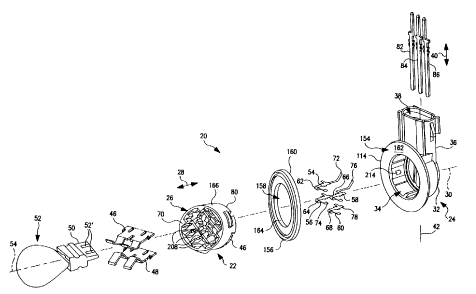
FIG. 1 is an exploded view of an angled lamp socket in accordance with
one embodiment of the present invention with a lamp added;
FIG. 2 is a perspective view of a lamp, and of lamp contact members and
terminal members of one embodiment of the present invention,
illustrating their operational relationship;
FIG. 3 is a perspective view of a lamp contact member in accordance
with one embodiment of the present invention;
FIG. 4 is a perspective view of a lamp contact member in accordance
with another embodiment of the present invention;
FIG. 5 is a perspective front view of the housing illustrated in FIG. 1
2 5 partially illustrating lamp contact members and terminal members
therein;
FIG. 6 is a front view of the body illustrated in FIG. l;
3 0 FIG. 7 is a rear view of the body illustrated in FIG. 1;
FIG. 8 is a perspective view of the lamp retaining members illustrated in
CA 02292936 1999-12-22
-6-
FIG. l;
ATTORNEY DOCKET NO. 98-2-831
PAGE 6 OF 27
FIG. 9 is a sectional view taken along lines 9-9 of FIG. 5 with all of the
remaining components of the angled lamp socket of FIG. 1 being
illustrated; and
FIG. 10 is a perspective rear view of a body in accordance with another
embodiment of the present invention.
BEST MODE FOR CARRYING OUT THE INVENTION
For a better understanding of the present invention, together with other
and further objects, advantages and capabilities thereof, reference is
made to the following disclosure and appended claims taken in
conjunction with the above-described drawings.
The embodiment of this invention that is illustrated in the drawings is
particularly suited for achieving the objects of this invention. FIG. 1
illustrates a lamp socket 20 embodying the present invention. Lamp
2 0 socket 20 provides a two piece insulator that is in the form of first and
second slidably engaging components including a body 22 and a housing
24. As will be apparent herein, the two piece insulator simplifies design
and assembly of the lamp socket. The body component '22 includes a
body cavity 26 that extends in a direction 28 of an axis 30.
Housing 24 includes a first portion 32 having a first housing cavity 34
and a second portion 36 having a second housing cavity 38. The first
housing cavity 34 extends in the direction 28 of axis 30. The second
housing cavity 38 extends in a direction 40 of an axis 42. The axis 42
3 0 extends at an angle 44, illustrated in FIG. 2, in relation to axis 30. In
the
embodiment illustrated in FIGS. l and 2, angle 44 is 90°, and the
angled
lamp socket 20 is a right angle lamp socket. The body 22 is connected to
CA 02292936 1999-12-22
-7-
ATTORNEY DOCKET NO. 98-2-831
PAGE 7 OF 27
the first portion 32 of housing 24 as described hereinafter.
The lamp socket 20 includes two lamp-retaining members in the form of
a first resilient retention member 46 and an opposite second resilient
retention member 48. In a preferred embodiment, the resilient retention
members are metal although other materials may be used. Retention
members 46 and 48 are structured and arranged for insertion into the
body cavity 26 to retain a wedge-like base 50 of a lamp 52, such as a
conventional S8 wedge base lamp, so that the lamp longitudinal axis 54
extends in the direction 28 when the lamp is inserted in the body cavity
26.
The lamp socket 20 includes a plurality of lamp contact members 54, 56,
58 and 60 in the body cavity 26. Each lamp contact member 54, 56, 58,
60 includes an end 62, 64, 66, 68, respectively, facing the front end 62 of
the body 22 and adapted to engage a respective lead wire 52' of lamp 52,
and an opposite end 72, 74, 76 and 78, respectively, extending out of the
body component 22 at rear end 80 of the body.
2 0 The lamp socket 20 includes a plurality of terminal members 82, 84, 86
at least a portion of each of that is in the housing 24. In the embodiment
illustrated in FIG. 1, the entire length of the terminal members 82, 84, 86
is in the housing 24. Each terminal member 82, 84, 86 extends from
housing cavity 34 to housing cavity 38 generally in the direction 40 of
2 5 the axis 42. Each terminal member engages a respective lamp contact
member in the housing cavity 34 as described hereinafter.
FIG. 2 illustrates the relationship between the lamp contact members 54,
56, 58 and 60 and the terminal members 82, 84 and 86. Lamp contact
3 0 members 54 and 56 are ground contacts that are electrically connected to
a common ground terminal member 82 at respective contact ends 72 and
74. Lamp contact member 58 is a minor contact that is electrically
CA 02292936 1999-12-22
_g_
ATTORNEY DOCKET NO. 98-2-831
PAGE 8 OF 27
connected to the minor terminal member 84 at end contact end 76.
Lamp contact member 60 is a major contact that is electrically connected
to the major terminal member 86 and contact end 78.
FIG.3 illustrates the configuration of the ground lamp contact member
54 and 56 and the major lamp contact member 60. Since each of such
lamp contact members is identical only the major lamp contact member
60 is illustrated in FIG. 3. The lamp contact member 60 includes an end
68 that engages and is electrically connected to a major lamp filament of
the lamp 52 and an end 78 that engages and is electrically connected to
the major terminal member 86. The end 68 is turned back towards an
intermediate length 88 and thereby provides a resilient end 68 that will
deflect when the lamp 52 is force fit into body cavity 26 thereby causing
the end 68 to exert a satisfactory force against the major lamp filament.
The end 78 includes a contact lead 90 that will extend from the body
cavity 26 when the angled lamp socket 20 is assembled. The contact
lead 90 includes a contact lead surface 92 that will engage a terminal
lead surface 94 of the major terminal 86 when the angled lamp socket 20
is assembled. The ends 68 and 78 of the lamp contact member 60 are
2 0 generally aligned with each other relative to axis 96. This, in
combination with the structure and arrangement of the body 22 and
housing 24, assures that the lamp contact member 60 will satisfactorily
engage the major lamp filament of the lamp 52 and the major terminal
member 86. In the embodiment illustrated in FIG. 3, the contact lead
2 5 surface 92 extends at an angle of 90° relative to axis 96. In one
embodiment, the contact lead surface 90 is 1.4 mm wide and the terminal
lead surface 94 is 2 mm wide. It will be readily apparent that the
foregoing comments are equally applicable regarding the ground lamp
contact members 54 and 56 and their relationship to respective ground
3 0 lamp filaments and terminal lead surface 94.
FIG. 4 illustrates the configuration of the minor lamp contact member
CA 02292936 1999-12-22
ATTORNEY DOCKET NO. 98-2-831
PAGE 9 OF 27
-9
58. Lamp contact member 58 includes an end 66 that engages and is
electrically connected to a minor lamp filament of the lamp 52 and end
76 that engages and is electrically connected to the minor terminal
member 84. The end 66 is turned back towards the intermediate length
98 and thereby provides a resilient end 66 that will deflect when the
lamp 52 is force fit into body cavity 26 thereby causing the end 66 to
exert a satisfactory force against the minor lamp filament of lamp 52.
The end 76 includes a contact lead 100 that will extend from the body
cavity 26 when the angled lamp socket 20 is assembled. The contact
lead 100 includes a contact lead surface 102 that will engage a terminal
lead surface 104 of the minor terminal 84 when the angled lamp socket
is assembled. The ends 66 and 76 of the lamp contact member 58 are
not aligned with each but are offset relative to axis 106. In particular, a
bridge 108 connects a length 110 and a length 112 thereby offsetting end
15 66 relative to end 76. Such offsets, in combination with the structure and
arrangement of the body 22 and housing 24, assures that the lamp
contact member 58 will satisfactorily engage the minor lamp filament of
lamp 52 and the terminal lead surface 104. In the embodiment illustrated
in F1G. 4, the contact lead surface 102 extends at an angle of 90°
relative
2 0 to axis 106. In one embodiment, the contact lead surface 102 is 1.4 mm
wide and the terminal lead surface 104 is 2 mm wide.
In considering the relationship between each lamp contact member 54,
56, 58 and 60 and respective terminal member 82, 84 and 86, each
2 5 contact lead surface engages a respective terminal lead surface in the
housing cavity 34. For example, with reference to FIG. 5, the ends 72,
74, 76 and 78 of lamp contact members 54, 56, 58 and 60, respectively,
extend into housing cavity 34 of housing 24 and engage respective
terminals. In particular, ends 72 and 74 of lamp contact members 54 and
3 0 56 engage terminal member 82, and ends 76 and 78 of respective lamp
contact members 58 and 60 engage respective terminal members 84 and
86. The nature of such engagement is illustrated in FIGS. 3 and 4. For
CA 02292936 1999-12-22
ATTORNEY DOCKET NO. 98-2-831
PAGE 10 OF 27
- 10
example, in FIG. 3 the contact lead surface 92 of end 78 engages
terminal lead surface 94 to provide a contact lead surface/terminal lead
surface interface. Identical type contact lead surface/terminal lead
surface interfaces are provided where the ends 72 and 74 engage terminal
82 and the end 76 engages the terminal 84.
Each respective lamp contact member is electrically connected to a
respective terminal member by either (a) a weld adjacent a contact lead
surface/terminal lead surface interface or (b) a spring biased engagement
between each respective lamp contact member and respective terminal
member at each respective contact lead surface/terminal lead surface
interface. Typically, all of the lamp contact members will either be
welded or spring loaded into engagement with a respective terminal
member. FIG. 3 is illustrative of a lamp contact member 60 welded to a
terminal 86 by a weld 108 adjacent the contact lead surface 92/ terminal
lead surface 94 interface. FIG. 4 is illustrative of a lamp contact member
58 spring biased into engagement with a terminal member 84 at the
contact lead surface 102/ terminal lead surface 104 interface. In the
embodiment of FIG. 4, the resilient contact lead 100 is deflected in
2 0 direction 110 as the contact lead surface 102 is compressed against the
terminal lead surface 104 when the body 22 is mated with the housing 24
as described herein. In those instances where the contact lead surface
102 and the terminal lead surface 104 are tin-plated surfaces, a deflection
that is sufficient to effect 4 Newtons of normal force in direction 112
2 5 between the contact lead surface and the terminal lead surface at the
interface therebetween will be adequate to provide the desired electrical
connection between the lamp contact member and the terminal contact
member. In the embodiments illustrated in FIGS. 3 and 4, contact lead
surfaces 92 and 102 are parallel to terminal lead surfaces 94 and 104,
3 0 respectively, to facilitate providing a satisfactory electrical
connection.
In the embodiment illustrated in FIG. 5, the housing cavity 34 extends
CA 02292936 1999-12-22
ATTORNEY DOCKET NO. 98-2-831
PAGE 1 1 OF 27
from a housing front end 114 to a housing base 116. The housing cavity
38 extends from housing end 118 towards the housing cavity 34, the two
housing cavities being separated by a housing wall 120. Although
separated, the two housing cavities 34, 38 are also connected by at least
one aperture extending through the wall 120 through that the terminal
members extend. In the embodiment illustrated in FIG. 5, there are three
apertures 122, 124 and 126. Terminal members 82, 84 and 86 extend
from cavity 34 to cavity 38 through apertures 122, 124 and 126,
respectively.
The lamp contact members are attached to the body 22 of the angled
lamp socket 20 by inserting the ends 62, 64, 66 and 68 into the body
cavity 26 at end 80. In this manner, the lamp contact members may be
suspended in the body cavity 26. Such suspension may be effected by
causing barbs that extend from each lamp contact member to engage
respective internal surfaces of the body 22. For example, with reference
to FIGS. 3 and 4, each lamp contact member, such as lamp contact
members 58 and 60, include pairs of barbs 128 and 130 that extend
laterally away from each other at the ends 66 and 68. FIGS. 6 and 7
2 0 illustrate the lamp contact members 54, 56, 58 and 60 having been
inserted into body cavity 26 from end 80 towards end 70. In viewing
FIG. 6, the ends 62, 64, 66 and 68 appear to be coming out of the sheet
of paper and the ends 72, 74, 76 and 78 appear to be going into the sheet
of paper. In viewing FIG. 7, the ends 62, 64, 66 and 68 appear to be
2 5 going into the sheet of paper and the ends 72, 74, 76 and 78 appear to be
coming out of the sheet of paper. With reference to FIG. 7, during such
insertion, the ends 62, 64, 66 and 68 are inserted into respective slots 132
located in body cavity 26. Slots 132 provide support for the lamp
contact members and are structured and arranged to also facilitate
3 0 guiding the lamp contact members into alignment with respective
terminal lead surfaces. With reference to FIG. 6, during such insertion,
the ends 62, 64, 66 and 68 are inserted between respective walls 134,
CA 02292936 1999-12-22
_12_
ATTORNEY DOCKET NO. 98-2-831
PAGE 12 OF 27
134' located in body cavity 26. The spacing between each pair of walls
134, 134' is such that upon insertion of a respective end 62, 64, 66 and
68, barbs 128 and 130 of each end are force fit between a respective pair
of walls 134, 134' to affix the lamp contact members within the body
cavity 26.
FIG. 8 is illustrative of one type of resilient retention member of the
present invention. FIG. 8 illustrates resilient retention member 48.
Retention member 46 is identical thereto. Retention member 48 is in the
form of a pair of retention beams represented by a first leg 136 and a
second leg 138 joined together at one end 140 by a common cross bar
142. The provision of a common cross bar 142 simplifies the stamping
and assembly process and adds strength to the retention members 46, 48.
Legs 136 and 138 extend from the cross bar 142 to respective distal
ends. The end 140 includes resilient bearing surfaces 144 and 146 that
engage respective angled ledges in body cavity 26 when the end 140 is
inserted into the body cavity at front end 70 as described hereinafter.
When the two pairs of resilient retention members 46, 48 are inserted
into the body cavity 26, the legs 136, 138 will extend from the cross bar
2 0 142 towards the body front end 70. In such an arrangement, the
respective lamp base retaining portions 148, 150 at the distal ends of
opposite retention beams 46, 48 will face each other as illustrated in FIG.
9. The resiliency of the legs 136, 138 and spacing between the opposing
retaining portions 148, 1 SO will be structured and arranged to permit the
2 5 wedge-type base 50 of the lamp 52 to be inserted between and grasped
and retained in place by the opposing retaining portions. The use of
opposing resilient retention members 46, 48 facilitates positioning a
lamp within the lamp socket 20 and improves lamp retention and
stability in the lamp socket in that the wedge-like base 50 is contained at
3 0 each of four corners of the base by a respective retaining portion 148,
150. The use of the metal spring-like retention members 46, 48
improves electrical conductivity and provides a reduction in lamp
CA 02292936 1999-12-22
ATTORNEY DOCKET NO. 98-2-831
PAGE 13 OF 27
-13
insertion force, yet maintains lamp withdrawal force to provide
satisfactory containment of the wedge-type base 50.
The angled lamp socket of the present invention may include a gasket for
sealing purposes. For example, the angled lamp socket 20 illustrated in
FIG. 1 includes a flange 154 at the end 114 of the housing portion 32.
An annular seal 156 is also provided. The body 22 extends through the
opening 158 of the annular seal when the lamp socket is assembled. The
annular seal is structured and arranged such that a surface 160 will
sealingly engage a flange surface 162, and a surface 164 will sealingly
engage an outer surface 166 of the body 22, when the angled lamp socket
is in a use mode as described herein.
In the embodiment illustrated in FIG. 5, the housing wall 120 includes
15 recesses 168, 170 and 172. The housing base 116 includes grooves 174,
176 and 178. The terminal members 82, 84 and 86 include arms 180,
182 and 184, and barbs 186, 188 and 190, respectively. The arms 180,
182 and 184 mate with respective recesses 168, 170 and 172 to facilitate
proper alignment of the terminal members with respective lamp contact
2 0 members. The terminal members 82, 84 and 86 are held in place by
being press fit into respective grooves 174, 176 and 178. The grooves
174, 176, 178 serve to prevent side to side motion of the terminal
members 82, 84 and 86, respectively, and to otherwise hold the terminal
members in place. The barbs 186, 188 and 190 engage the inner walls of
2 5 respective apertures 122, 124 and 126 to further hold in place respective
terminal members 82, 84 and 86.
The angled lamp socket of the present invention may include a sealant
between the terminal members and the apertures) in the housing wall
3 0 that separates the first housing portion from the second housing portion.
For example, the angled lamp socket 20 illustrated in FIG. 5 comprises
pockets 192, 194 and 196 adjacent respective recesses 168, 170 and 172.
CA 02292936 1999-12-22
ATTORNEY DOCKET NO. 98-2-831
PAGE 14 OF 27
-14
Pockets 192, 194 and 196 may be about 1.5 mm deep. A sealant 198,
200 and 202 is provided in respective pockets 192, 194 and 196.
The method of assembling the angled lamp socket of the present
invention will now be described with reference, for example, to the
angled lamp socket 20 illustrated in the drawings.
The body 22 is prepared by inserting the resilient retention members 46
and 48 into the body cavity 26 at end 70. For example, in the
embodiment illustrated in FIG. 9, the retention members 46 and 48 are
inserted into respective slots 206 and 208 provided within the cavity 26.
As the retention members are inserted into body cavity 26 towards end
80, the resilient bearing surfaces 144, 146 engage respective angled
ledges 208 provided within the body cavity 26. The resilient bearing
surfaces 144 and 146, and the angled ledges 208, are structured and
arranged such that the opposing resilient retention members 46 and 48
will be urged towards each other to provide spring loaded opposing pairs
of lamp base retaining portions 148, 150 that engages opposite surfaces
of the lamp base 50 to firmly hold the lamp 52 in place. When a lamp 52
2 0 is inserted into the body cavity 26, the lamp axis 54 will extend in the
direction 28 of the body axis 30.
The body 22 is further prepared by inserting a plurality of lamp contact
members into the body cavity 26 such that each contact lead surface
2 5 extends away from the end 70 of the body 22. For example, in the
embodiment illustrated in FIGS 6 and 7, the ends 62, 64, 66 and 68 of
body contact members 54, 56, 58 and 60 are inserted into respective slots
132 and urged towards end 70 until the lamp contact members are in
place. For example, in the embodiment illustrated in FIG. 6, each lamp
3 0 contact member is in place with the barbs 128 and 130 engaging
respective walls 134, 134'.
CA 02292936 1999-12-22
ATTORNEY DOCKET NO. 98-2-831
PAGE 15 OF 27
-15-
The housing 24 is prepared by inserting a plurality of terminal members
into the housing such that each terminal lead surface extends towards the
end 114 of the housing. For example, in the embodiment illustrated in
FIG. 5, the terminal members 82, 84 and 86 are inserted into housing
cavity 38, then through respective apertures 122, 124 and 128 and into
housing cavity 34. During such insertion, the terminal members 82, 84
and 86 are press fit into grooves 174, 176 and 178. The terminal
members are inserted into the housing 24 until the arms 180, 182 and
184 are mated with respective recesses 168, 170 and 172, and barbs 186,
188 and 190 engage inner walls of respective apertures 122, 124 and
126.
The body is then inserted into the housing by inserting a portion of the
body into a housing cavity and engaging each terminal lead surface with
a respective contact lead surface thereby providing respective contact
lead surface/terminal lead surface interfaces. When an annular gasket is
used, the body is first inserted through the gasket. Foi~ example, with
reference to FIGS. 1 and 9, the end 80 of the body 22 is inserted through
opening 158 of the annular gasket 156 and then into the housing cavity
2 0 34 until the contact lead surfaces, such as surfaces 92 and 102 engage
respective terminal lead surfaces, such as 94 and 104 as illustrated in
FIGS. 2, 3, 4, 5 and 9 (In FIG. 9, the terminal member 84 is not visible, it
being blocked by terminal member 86).
2 5 After the body is inserted into the housing in this manner, each contact
lead surface is connected electrically to a respective terminal lead
surface. In the embodiment illustrated in FIG. 9, such electrical
connection may be effected by inserting the body 22 into housing cavity
34 sufficiently to deflect each contact lead as illustrated in FIG. 4 with
3 0 respect to contact lead 100 so as to provide a satisfactory normal force
between each respective contact lead surface and a respective terminal
lead surface at each respective contact lead surface/terminal lead surface
CA 02292936 1999-12-22
-16-
ATTORNEY DOCKET NO. 98-2-831
PAGE 16 OF 27
interface. In such an embodiment, the outer surface 166 of body 22, and
the inner surface 210 of the housing cavity 34 may be provided with one
or more respective mating latch member 212 and 214 as illustrated in
FIG. 1 that are structured and arranged to lock together the body and the
housing when the contact leads have been deflected to the extent desired.
In the embodiment illustrated in the drawings, two latch members 212
and respective mating latch members 214 are provided. If desired, a
weld may also be provided at each contact lead surface/terminal lead
surface interface.
In the alternative, rather than relying upon a biased contact lead
surface/terminal lead surface interface, each contact lead may be welded
to a respective terminal adjacent respective contact lead surface/terminal
lead surface interfaces. In such embodiment, after the body portion is
inserted into the housing cavity so that each contact lead surface engages
a respective terminal lead surface, respective contact leads and terminals
are welded together. Such welding may be effected through the front
end 70 of the body. For example, with reference to FIGS. 6 and 7, the
body 22 includes openings or windows 216, 218, 220 and 222 that
2 0 provide access to a respective contact lead surface and terminal lead
surface such as contact lead surfaces 92 and 102 and respective terminal
lead surfaces 94 and 104, respectively. By providing windows 216, 218,
220 and 222, welds such as weld 108 illustrated in FIG. 3 may be
effected by, for example, focusing a laser at front end 70 of the body 22
2 5 through the body cavity 26 at each window to provide each respective
weld. Each window may be, for example, 4mm by 4mm and extend
through the body.
Alternatively, welding may be effected in a similar manner by resistance
3 0 welding by applying electrodes through respective windows and placing
one electrode on a contact lead and another electrode on a respective
terminal lead to that the contact lead is to be welded.
CA 02292936 1999-12-22
ATTORNEY DOCKET NO. 98-2-831
PAGE 17 OF 27
_17_
A sealing step may be used to seal the terminal members within the
housing cavity. For example, in the embodiment illustrated in FIG. 5,
such sealing may be effected by providing a curable epoxy in the pockets
192, 194 and 196 of wall 120 of the housing 24 to form sealants 198, 200
and 202. Without limitation, a curable epoxy such as Nuvasil may be
used.
When the angled lamp socket 20 is attached to a member 224 in a
conventional manner as illustrated in FIG. 9, the annular gasket 156 will
be compressed to the extent that gasket surface 160 will sealingly engage
flange surface 162, and gasket surface 164 will sealingly engage outer
surface 166 of body 22. When a lamp 52 is inserted into cavity 26, the
angular lamp socket will be sealed from environmental features such as
moisture by the annular gasket 156 and the sealants 198, 200 and 202
thereby protecting the electrical connections within the angular lamp
socket.
The angular lamp socket of the present invention may be readily used
2 0 when different focal lengths are required. This is accomplished merely
by increasing the length of the body 22 and lamp contact members 54,
56, 58 and 60. The other features of the angulax lamp socket 20, such as
the positioning of the mating latch members 212 and 214, may remain
the same. This allows for reduced tooling and inventory costs. In those
2 5 instances where longer lamp contact members 54, 56, 58 and 60 are
required to accommodate applications having a higher focal length,
provision may be made for restraining the contact leads of the lamp
contact members. For example, the body cavity may be provided with at
least one rib. In addition, each lamp contact member may comprise a
3 0 hook that engages such rib to restrain the contact lead of the contact
member and to maintain alignment of the respective contact lead surface
with a respective terminal lead surface. For example, body 22' of FIG.
CA 02292936 1999-12-22
ATTORNEY DOCKET NO. 98-2-831
PAGE 18 OF 27
-18-
includes a body cavity 26' that includes two ribs 226, 228. In order to
simplify the drawing, only two lamp contact members 72' and 76' are
illustrated. Except as described herein, lamp contact members 72' and
76' are longer than, but otherwise identical to, lamp contact members 72
5 and 76. Other than length, the difference is that lamp contact members
72' and 76' each include a hook 230 and 232, respectively, adjacent
respective contact leads such as contact lead 100' of lamp contact
member 76'. When a lamp socket is assembled using a body 22', the
lamp contact members 72' and 76' are inserted at end 80' of body 22' into
10 the body cavity 26' until the hooks 230 and 232 engage the rib 226.
Such engagement provides support for and otherwise restrains the lamp
contact members 72' and 76' within the body cavity 26' that facilitates
positioning the contact lead surface for consistent welding.
Fabrication of the angled lamp socket of the present invention may be
accomplished using conventional procedures. For example, the lamp
contact members, lamp retention members and terminal members may
be stamped from a metal sheet and then rolled and/or bent as required to
form the desired configuration. In the embodiment as illustrated in the
2 0 drawings, the lamp retention members are stainless steel and the lamp
contact members and terminal members are brass. The body and
housing may be molded from a plastic material. For example the body
and housing illustrated in the drawings are molded from PPA (poly
phthalamide) and PBT (poly butylene teraphthalate), respectively. The
2 5 seal may be molded from a thermoplastic elastomer. The sealant may be
a curable liquid sealant such as an epoxy such as Nuvasil.
The embodiments that have been described herein are but some of
several that utilize this invention and are set forth here by way of
3 0 illustration but not of limitation. It is apparent that many other
embodiments that will be readily apparent to those skilled in the art may
be made without departing materially from the spirit and scope of this
CA 02292936 1999-12-22
ATTORNEY DOCKET NO. 98-2-831
-19-
PAGE 19 OF 27
invention.