Note: Descriptions are shown in the official language in which they were submitted.
CA 02292969 1999-12-22
1
A water catchment device floating at the surface of a
basin and supplying a pumping system
The present invention relates to improvements made
to water catchment devices (skimmers) at the surface of
a basin, in particular to supply a water filtering
system for the basin, and more specifically improvements
made to devices of this type which are of a floating
design.
The skimmers commonly used in conjunction with
water basins such as swimming pools are maintained at a
correct level relative to the water surface in the basin
by attaching them, possibly adjustably, to a fixed
element of the basin (for example a wall, ladder).
However, there is such a thing as a "free" skimmer,
i.e. one which is not joined to a fixed element of the
basin and which floats on the free surface of the water
during normal operation. Since the skimmer is made from
materials of a density higher than 1, on the one hand,
and the body of the skimmer partially filled with water
behaves like a hollow body on the other, it is the level
of the water inside the body of the skimmer which
determines the relative degree of rising and sinking
CA 02292969 1999-12-22
2
vertical forces to which the skimmer is subjected and
determines whether the skimmer is "buoyant" or "sinking"
(or "skimming").
More specifically, the water level inside the
skimmer body varies, in particular depending on the
suction rate of the pump and disruptions affecting the
intake of water to the skimmer body (for example
extensive clogging of the filter basket, jamming of the
floating dish above the water level, etc.).
If an imbalance occurs in the flow of water across
the skimmer and the rate at which water flows by gravity
through its inlet into the skimmer body is reduced or
even halted (by an obstruction at the inlet screen, for
example) and becomes lower than the rate at which water
is sucked in by the pump, the skimmer body empties and
the pump fails.
Accordingly, the objective of the invention is to
overcome this drawback and propose an improved design
for a floating device of this type so that even if the
water entering the skimmer body by gravity is reduced or
interrupted, the pump can not shut down, the improved
device nevertheless remaining simple in structure and
made from parts which are easy and inexpensive to
CA 02292969 1999-12-22
3
manufacture, and such that operation of the device will
require no intervention to switch from one operating
mode in a normal situation to another operating mode in
an abnormal situation or in the event of deterioration.
To this end, the invention proposes a water
catchment device which floats at the water surface of a
basin, in particular to supply a water filtering system,
comprising:
- a floating support having a support base and
- a skimmer arranged inside said floating support and
retained on said base, this skimmer comprising:
~ a skimmer body provided with stop means designed
to allow restricted vertical displacement thereof
above the base,
~ the skimmer body having a base which has a
central main orifice which can be connected to a
pumping means and which has at least one auxiliary
passage designed to be closed off by said base
when the skimmer body is resting thereon and
~ a floating dish which sits at the top of the
skimmer body and which is provided with an axial
opening.
CA 02292969 1999-12-22
4
A device of this type overcomes the disadvantages
outlined above and prevents the pump from shutting down:
a) when the device is functioning normally, the
floating dish is maintained below the water level
of the basin and takes in through its axial opening
a lamellar flow of water which falls into the
skimmer body before being drawn in through the main
orifice under the action of the pumping means
whilst the skimmer body, partially filled with
water, is "skimming" and is held down against the
base: the auxiliary passage provided in the base of
the skimmer body is therefore closed off by the
base;
b) during abnormal operation when the skimmer body has
excessive buoyancy because it is not filling up
with water, it becomes "buoyant" and raises the
floating dish above the water level of the basin,
cutting off the intake of water into the skimmer:
the skimmer body will then rise above the base,
releasing the auxiliary passage so that the water
from the basin can penetrate the body via said
auxiliary passage thus released and is drawn in
through the central orifice by the pumping means.
CA 02292969 1999-12-22
In one particular embodiment, the base has an
annular plate in which a connector linking the skimmer
body to the pumping means loosely engages, a free space
being left between said connector and the inner edge of
the annular plate for the reflux of water from the basin
when the device is operating under abnormal conditions.
The base can then be provided with at least one member
protruding radially from the periphery of the annular
plate towards the interior to form a stop that will
retain the skimmer body vertically; it is of practical
use if the protruding member is an annular wing and the
base is of a [ shape in cross section.
Advantageously, if the skimmer body is made from a
low density material, such as a low density plastic, for
example, the skimmer body may be provided with a ballast
so that its density becomes substantially greater than
1.
The invention will be more readily understood from
the detailed description of a preferred embodiment,
which is given solely by way of example and is not
restrictive in any respect. Throughout the description,
reference will be made to the appended drawings in which
figures 1 and 2 provide schematic illustrations, in
CA 02292969 1999-12-22
6
section, of a preferred embodiment of a device having
the design proposed by the invention and showing two
different operating situations respectively.
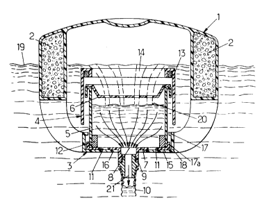
Figure 1 illustrates a water catchment device
floating on the free water surface of a basin such as a
swimming pool, specifically designed to supply a water
filtering system for the basin. Such devices are
commonly referred to as skimmers or incorporate a
skimmer.
The device illustrated in figure 1 has a floating
support l, which is designed in any manner that will
enable it to float at the surface of the basin (due to
the choice of materials; inclusion or one or more floats
2 made from a material with a density substantially less
than l, for example foam).
The floating support 1 has a base 3 designed to
accommodate, inside said support 1, a skimmer which is
denoted as a whole by reference number 4.
The skimmer 4 has a skimmer body 5 in the shape of
a box which is open at the top. As a general rule, a
screen 6 rests on the top edge of the skimmer body,
designed to hold back any coarse debris (leaves, paper,
branches,...) The skimmer body 5 has a base 7 provided
CA 02292969 1999-12-22
with a main orifice at the centre to give access to a
connector 9 for attaching a flexible hose 10 providing a
connection to pumping and filtering means (not
illustrated), in principle located externally to the
basin.
Furthermore, the base 7 of the skimmer body 5 is
provided with one or more auxiliary passages 11 arranged
between the main orifice 8 and the peripheral edge.
The skimmer body is constructed in such a way that
it is of a density that is close to but substantially
greater than 1 so that it will naturally "skim". It may
be made from a material that will produce this effect or
alternatively it may be made from a material whose
density is substantially less than 1 and weighted, for
example by means of a ballast ring 12 which, in the
embodiment illustrated, rests on its base and conforms
to the internal contour as illustrated in figure 1.
The skimmer body 5 has at its head a dish 13 of a
density slightly less than 1 and hence naturally
"buoyant". The floating dish 13 may be made from a
material of a density slightly less than 1 or,
alternatively, made by made from a material with a
density greater than 1 and provided with a float means
CA 02292969 1999-12-22
g
such as a foam ring as illustrated in figure 1. At the
top, this dish 13 has an axial opening 14 constituting a
water inlet to the skimmer.
The above-mentioned base 3 has an annular plate 15
located underneath the base of the skimmer and provided
with a central orifice 16 in which the connector 9
joined to the base 7 of the skimmer body engages. A free
space 16a is left between the edges of the orifice 16
and the connector 9 inserted in it.
Located at a distance above the plate is a radially
extending stop member directed towards the interior,
designed to limit the degree of vertical displacement of
the skimmer body 5 above the annular plate 15.
Advantageously, the stop member 17 is an annular wing
parallel with the plate 15 and joined to it by means of
a vertical skirt 18 so that the base is of a [ shape in
cross section.
Co-operating with the stop member 17 and provided
on the skimmer body 5 is a radial protrusion 17a which
may be the periphery, for example, and may be a
peripheral zone of the base 7 extending beyond the side
wall of the skimmer body 5.
The device operates in the following manner.
CA 02292969 1999-12-22
9
When operating under normal conditions (see figure
1), the floating dish 14 is located immediately below
the free surface of the water in the basin 19, in
equilibrium under the action of the different forces to
which it is subjected. The floating dish may therefore
follow slow variations in the free surface 19 allowing a
lamellar flow of water to flow into the skimmer body,
entraining debris floating on the free surface 19 with
it, due to the surface effect.
The water drops through the screen 6 into the
skimmer body, which it fills up to a level 20 whilst
being drawn by the pumping means through the outlet
orifice 8 (arrow 21).
Under these normal operating conditions, the
skimmer body is "skimming" and rests on the annular
plate 15 of the base 3, which is in turn supported at a
predetermined distance below the free level 19 due to
the floats 2 of the support 1. In this position, the
auxiliary passage or passages 11 provided in the base of
the skimmer body 5 are closed off by the annular plate
15 of the base 3.
When operating under abnormal conditions or in the
event of deterioration when water is no longer flowing
CA 02292969 1999-12-22
1~
into the skimmer body or is not flowing into it at an
adequate rate, due to debris 22 obstructing the screen
for example (see figure 2), the output flow rate of the
water from the skimmer body imposed by the pumping means
will cause the skimmer body to run dry sooner or later.
The skimmer body, almost empty, then becomes
"buoyant" and rises above the annular plate 15 until it
comes to a stop against the annular retaining wing 17,
driving with it the floating dish, the top edge of which
moves above the free surface 19.
In this situation, the auxiliary passage or
passages 11 are released and the water from the basin
passes through the free space 16a and these passages 11
into the skimmer body, where it is drawn by the pumping
means through the outlet orifice 8.
The weight of the ballast 12 can be determined so
that the skimmer body is raised and the auxiliary
passages 11 released whilst a small quantity of water,
introduced normally via the opening 14 in the floating
dish, remains inside the skimmer body.
Accordingly, the skimmer body will be prevented
from drying out completely, thereby avoiding a resultant
CA 02292969 1999-12-22
ll
shut-down of the pumping means and the associated risk
of damage or even total failure thereof.
The means of implementation remain structurally
simple and above all require no manual intervention to
switch from operation under normal conditions to
operation under abnormal conditions.
Finally, the various component parts are simple and
inexpensive to manufacture (from moulded plastic, for
example) and the price of a floating device of this
design can be kept relatively modest.