Note: Descriptions are shown in the official language in which they were submitted.
CA 02293001 1999-12-21
-1-
SOLID BLUNT FOR A NEEDLE ASSEMBLY
FIELD OF TIE INVENTION
The present invention relates to medical devices and other similar devices and
in particular to medical devices such as intravenous catheters and syringes
which
include a hollow needle having a sharp distal end for piercing an object, such
as the
skin of a patient.
BACKGROUND OF THE INVENTION
The existence of infectious diseases has highlighted the danger to which
medical personnel may be exposed when treating patients by means of catheter
devices
and syringes where a sharp needle point is used to pierce the skin of the
patient. In
order to protect medical personnel against inadvertent needle stick, a number
of
solutions have been developed whereby a protective mechanism, incorporated
within a
catheter or syringe, prevents physical contact with the sharp needle point
after use and
hence protects against inadvertent needle stick. Many of the developed
solutions are
complicated. For example, some developments utilize the retraction of the
needle
within a housing once the needle has been used. Other developments utilize
blunts
which are contained within the cannula of the hollow needle.
These blunts come in two principal forms: hollow blunts which are hollow
tubes concentrically disposed within the circular shaft of a hollow needle,
and solid
blunts. Hollow blunt designs require that an exit hole be provided at a
proximal
location to allow blood to exit the blunt and enter a flash chamber, the use
of which is
CA 02293001 1999-12-21
-2-
well known in the art. In order for blood flashback to be seen as quickly as
possible,
the exit hole needs to be located just proximal to the butt end of the needle.
Thus,
hollow blunts require extra machining or manufacturing steps in order to
produce a
satisfactory hollow blunt. Solid rod blunts are typically cylindrical rods
which have
an outer diameter which is sufficiently smaller than the inner diameter of the
shaft of
the cannula of the needle in order to allow clearance for fluid flow all
around the
diameter of the solid rod blunt. While some prior art designs have included
grooves
in the solid rod blunt, these solid rod blunts nevertheless position the wall
of the blunt
(the outside diameter of the blunt) some distance from the inner diameter of
the shaft
of the cannula.
Figure 1A illustrates an example of a prior art solid blunt 103 within the
shaft 105 of the needle assembly 101. The needle 107 includes a hollow opening
109
and a sharp tip 107 at the end of the opening. The needle assembly 101 is
shown in
Figure 1A before its use. In this situation, the solid rod blunt 103 is
disposed
entirely within the shaft of the needle 105 such that the sharp point 107 can
pierce an
object, such as the skin of a patient. After use, the solid rod blunt 103 is
advanced
longitudinally along the longitudinal axis 120 shown in Figure 1B such that
the end
111 of the solid blunt 103 extends beyond the opening of the shaft 105,
thereby to
some extent covering the sharp tip 107 so that a user of the needle may not
receive an
accidental needle stick. As is well known in the art, a clip or other
mechanism holds
the solid blunt rod 103 relative to the shaft 105, preventing it from moving
longitudinally along the axis 120 once the blunt 103 has been extended beyond
the
opening. However, as shown in Figure 1C, it is also possible for the solid
blunt
CA 02293001 1999-12-21
-3-
103 to move perpendicularly to the longitudinal axis 120 and this tends to
increase the
gap between the blunt and the sharp tip which tends to increase the likelihood
of an
accidental needle stick or skive. Figure 1C shows a cross-sectional view of
the
assembly 101 shown in Figure 1B at the line IC-1C shown in Figure 1B. As can
be seen from Figure 1C, there is a considerable gap 109a between the inner
diameter
of the shaft 105 and the outer diameter of the solid blunt rod 103. This makes
it
possible for the rod to move up and down along the axis 130 which is
perpendicular
to the longitudinal axis 120 shown in Figure 1B. As a result, it is possible
for the
blunt 103 to be pushed away from the sharp tip 107 even when it is extended
out
beyond the tip 107 as shown in Figure 1B. As a result, even though the blunt
may
be advanced longitudinally beyond the end of the sharp tip of the needle, the
gap
between the wall of the blunt and the sharp tip may be so large that the sharp
point is
permitted to scratch or skive a person's skin. Naturally, the solid blunt must
provide
space around its circumference in order to permit fluid flow, and thus it
would appear
that a gap 109a is required.
From the above discussion, it can be seen that it is desirable to provide an
improved solid blunt which better protects a user of a needle.
CA 02293001 1999-12-21
-4-
SUMMARY OF THE INVENTTON
The present invention provides a solid blunt which helps to prevent accidental
needle sticks. The present invention also provides a needle assembly having a
solid
blunt.
In one exemplary embodiment, a solid blunt has an outer dimension (e.g.
outer diameter) which is nearly equal to an inner dimension (e.g. inner
diameter) of a
cannula of a needle which is configured to contain the solid blunt.
In one example, the solid blunt substantially blocks fluid flow along a first
circumferential portion of an inner diameter of the cannula and allows fluid
flow in a
second circumferential portion of the inner diameter. The solid blunt is
typically
capable of longitudinal movement through the cannula and is prevented from
moving
substantially in a direction perpendicular to the longitudinal movement.
A needle assembly, in another exemplary embodiment, includes a solid blunt,
a cannula, and a clip which couples the solid blunt to a frame which is
coupled to the
cannula. The clip allows the solid blunt to move longitudinally between at
least two
positions and the clip prevents the solid blunt from rotating within the shaft
of the
needle. The solid blunt itself is effectively lodged within the shaft of the
needle so that
it cannot move substantially in a direction perpendicular to the longitudinal
movement
of the solid blunt.
The present invention may be used with medical devices, including needles,
catheter assemblies and introducers for catheters and other devices as well.
CA 02293001 1999-12-21
-5-
BRIEF DESCRIPTION OF'1'IIE DRAWINGS
The present invention is illustrated by way of example and not limitation in
the
figures of the accompanying drawings in which like references indicate similar
elements.
Figure 1A shows a cross-sectional view of a prior art blunt within a needle
shaft. This view depicts the typical position of the blunt relative to the
shaft and tip of
the needle before use of the needle.
Figure 1B shows a cross-sectional view of a prior art needle assembly
having a blunt which is extended beyond the tip of the needle after use of the
needle.
Figure 1C shows a cross-sectional view of a solid blunt within a needle
shaft; this cross-sectional view is taken along the line 1 C-1 C shown in
Figure 1B.
Figures 2A, 2B, 2C, and 2D show cross-sectional views of four examples
of solid blunts according to the present invention.
Figures 3A, 3B, 3C, and 3D show cross-sectional views of the blunts
shown respectively in Figures 2A, 2B, 2C, and 2D within the shaft of a needle.
Figures 3A, 3B, 3C, and 3D also illustrate the relative position of portions
of the
blunt and the sharp tip 311 of the needle and blunt assembly.
Figure 3E shows the perspective side view of a needle and blunt assembly
according to the present invention.
Figure 4A shows another cross-sectional view of an example of a specific
solid blunt according to the present invention.
Figure 4B shows another example of a specific solid blunt according to the
present invention.
CA 02293001 1999-12-21
-6-
Figures 5A and 5B show cross-sectional views of an example of a catheter
assembly which may use a solid blunt according to the present invention.
CA 02293001 1999-12-21
-7-
DETAILED DESCRIPTION
The present invention provides various examples of solid blunts and needle
assemblies containing solid blunts. The following description and drawings are
illustrative of the invention and are not to be construed as limiting the
invention.
Numerous specific details are described to provide a thorough understanding of
the
invention. For example, very specific geometries and dimensions are provided
for
purposes of illustrating the invention. In certain instances, well known or
conventional details are not described in order to not unnecessarily obscure
the present
invention in detail.
Generally, a solid blunt according to the present invention has an outer
dimension, such as an outer diameter, which is nearly equal to (e.g. just less
than) an
inner dimension, such as an inner diameter, of a cannula of a needle which is
configured to contain the solid blunt. At least a portion of the solid blunt
having this
outer dimension is configured to be positioned near a sharp tip of the needle
when the
blunt is positioned to protect against needle skiving, such as when the blunt
is
extended longitudinally out beyond the opening of the needle. The solid blunt
is
formed in a manner to provide a fluid flow through a fluid path of sufficient
size while
positioning the surface of the blunt (e.g. the outside diameter) as close to
the sharp
point of the needle (e.g. inside diameter) as possible. Thus, at least a
portion of the
solid blunt may substantially block fluid flow along a first circumferential
portion of
an inner diameter of the cannula while allowing fluid flow in a second
circumferential
portion of the inner diameter. A typical blunt according to the present
invention may
be capable of longitudinal movement through the cannula but be prevented from
CA 02293001 1999-12-21
-8-
moving substantially in a direction which is perpendicular to the longitudinal
movement. By being prevented from moving in this perpendicular direction, the
outside dimension of the blunt will be positioned close to the sharp point of
the needle
and thereby reduce the likelihood that the sharp point will scratch or skive a
person's
skin.
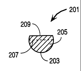
Figure 2A shows an example of a solid blunt 201 which has one particular
geometry which resembles the letter "D" in the cross-sectional view of the
solid blunt
201. This solid blunt 201 includes an outer circumferential portion or surface
203 and
an upper flat portion 209. The solid interior 205 of the blunt extends from
the
circumferential portion 203 beyond the centerline 207 and up to the flat
portion 209.
The centerline 207 is designed to be the central diameter of a cannula which
receives
the solid blunt 201.
Figure 3A shows an example of a needle assembly 301 which includes the
solid blunt 201 and the shaft 303 of a needle. The solid blunt is disposed
within the
shaft of the needle 303 such that the bulk of the solid blunt is positioned
near the
needle's sharp tip 311 which is shown diagrammatically in the cross-sectional
view of
Figure 3A. As can be seen from Figure 3A, the circumferential portion 203 of
the
outer surface of the solid blunt is closely positioned to the inner diameter
307 of the
shaft 303. Thus very little gap 309 exists between the blunt 201 and the shaft
303
along at least a fust circumferential portion of the inner diameter of the
shaft 303.
However, fluid flow is allowed to occur through the opening 305 which exists
above
the solid blunt 201 as shown in Figure 3A. The blunt 201 includes material at
or
above the centerline 207 as shown in Figure 3A so that the blunt cannot move
CA 02293001 1999-12-21
-9-
substantially in a perpendicular direction relative to the longitudinal
movement of the
blunt 201 within the shaft 303. That is, by having solid material of the blunt
at or
above the centerline of the shaft 303, the blunt resists movement in this
perpendicular
direction.
Figure 2B shows another example of a particular geometry of a solid blunt
according to the present invention. This particular geometry is referred to as
a pie-
slice shaped solid blunt due to the fact that the cross-section of the blunt
as shown in
Figure 2B resembles a pie slice. The blunt 211 of Figure 2B includes a first
circumferential portion or outer surface 213 and a second circumferential
portion or
outer surface 215. Each of these circumferential portions are designed to come
in
close contact with the inner diameter of the shaft 303 as shown in Figure 3B.
In one
case, the outer diameter of the blunt is nearly equal to (but just less than)
the inner
diameter of shaft 303. Thus, only a very small gap exists between the portion
213
and the inner diameter 307 of the shaft 303 as shown in Figure 3B. The solid
interior 219 of the blunt 211 extends from one circumferential portion to the
other
circumferential portion, thereby resisting perpendicular movement of the
blunt.
Figure 2B shows in its cross-sectional view a particular geometry in which the
sides
217a and 217b are straight. It will be appreciated that alternatively the
sides 217a and
217b may be either concave or convex.
Figure 2C shows another specific geometry of a solid blunt according to the
present invention. The solid blunt 221 shown in the cross-sectional view of
Figure
2C includes a cut-out region 229. Even with the cut-out region, a solid
portion 223
of the blunt 221 extends beyond the centerline 231 of the shaft 303 as shown
in
CA 02293001 1999-12-21
-10-
Figure 3C. Accordingly, the solid blunt 221 will resist perpendicular movement
as
described above. The outer circumferential portion 225 of the solid blunt 221
has a
diameter which is nearly equal to (but just less than) the diameter of the
shaft 303 and
thus very little space or gap 309 exists between the outer surface of the
solid blunt and
the inner diameter 307 of the shaft 303. Also as shown in Figure 3C, the blunt
is
positioned relative to the sharp tip 311 so that a majority of the solid blunt
material will
be disposed next to the sharp tip 311.
Figure 2D shows another example of a particular geometry of a solid blunt
according to the present invention. In the cross-sectional view of Figure 2D,
the
10. blunt 241 includes a D-shaped cut-out 249 in the upper surface 251 of the
blunt.
Sufficient solid material 245 of the blunt is at or above the centerline 247
of the shaft
303 as shown in Figure 3D. The outer circumferential portion 243 of the blunt
241
is sized relative to the inner diameter of the shaft 303 such that very little
gap 309c
exists between the inner diameter of the shaft 303 and the outer circumference
of the
blunt 241. The blunt 241 is positioned relative to the sharp tip 311 so that
most of its
solid material will be positioned near the tip 311.
Figure 3E shows a side perspective view of the assembly 301 shown in
Figure 3A. The cross-sectional view of Figure 3A is shown by line 3A-3A of
Figure 3E. The needle assembly 301, as shown in Figure 3E, includes the solid
blunt 201 which is disposed within the hollow inner diameter of the cannula
fontned
by the shaft 303. The inner diameter 307 of the shaft 303 is nearly equal to
(but just
less than) the outer diameter of the blunt 201 such that the gap 309 is very
small. The
gap 305 between the top of the solid blunt 201 and the inner diameter 307
provides a
CA 02293001 1999-12-21
-11-
sufficient fluid path through the shaft 303 when the needle is used. On the
other
hand, the close proximity between the outer circumferential portion 203 of the
blunt
201 and its corresponding inner circumferential portion of the shaft 303 is
such that
fluid flow through the gap 309 is relatively restricted. The centerline 207 of
the shaft
303 is shown relative to the solid blunt 201. It can be seen that a portion of
the solid
material of the solid blunt is at or above the centerline, thereby preventing
the blunt
from moving perpendicularly along the perpendicular direction 357 shown in
Figure
3E. The blunt is capable of moving longitudinally along the longitudinal axis
353
under control of a conventional clip or other device (not shown) which is
coupled to
the blunt 201. This device, such as a clip, may be attached directly to the
blunt or
through an intermediary piece which may have a different profile such as the
rod 351
shown in Figure 3E. The rod 351 does not need to perform the functions of the
solid blunt 201 and thus may have a different geometry than the solid blunt
201. The
required geometry of the solid blunt 201 should exist around portions of the
blunt that
will be near the sharp tip 311. The clip or other device which controls and
positions
the solid blunt 201 may be similar to those devices in the prior art, such as
those
shown in U.S. Patents 5,009,642, or 5,540,662, or 4,828,547, or 5,743,882.
These clips or devices, using conventional mechanisms, allow for the blunt to
move
longitudinally but prevent the blunt from moving circularly (e.g. rotating)
within the
shaft 303; this circular direction is shown by the arrow 355 shown in Figure
3E.
Thus by using a conventional clip or other device for retaining and
controlling the
movement longitudinally of the blunt 201, the blunt 201 may be prevented from
rotating (and thus stay positioned properly relative to the sharp tip 311)
while also
CA 02293001 1999-12-21
-12-
allowing for longitudinal movement along the axis 353 as shown in Figure 3E.
The
geometric configuration of the blunt according to the present invention will
also
prevent perpendicular movement along the axis 357 as shown in Figure 3E.
Figures 4A and 4B show respectively particular examples of the D-shaped
solid blunt and the pie-slice shaped solid blunt according to the present
invention.
These particular figures and the following tables provide various specific
examples for
dimensions which are specified in the following tables. In particular, Table A
below
specifies examples for particular dimensions of the D-shaped blunt relative to
certain
specific needle shafts. Similarly, Table B shows examples of specific
dimensions for
the pie-slice shaped blunt of Figure 4B. The tables show the nominal inner
diameter
(ID) of the needle and show the nominal outer diameter (OD) of the blunt. It
can be
seen that the OD of the blunt is less than but nearly equal to the ID of the
needle. In a
typical case, the OD of the blunt is 0.002 inches less than the ID of the
blunt. The
labels on the Figures 4A and 4B represent the same labeled dimensions in the
Tables A and B (for example, "A" in Figure 4A is a dimension shown in the
column
A ["Nominal Blunt OD"] of Table A). These examples of Figures 4A and 4B
assume a cylindrical shape for the needle's shaft and the blunt so that a
diameter may
be used to describe the relative dimensions. It will be appreciated that other
geomeu-ies for the needle and blunt may be used with the present invention;
for
example, a needle and a blunt each having triangular or elliptical cross-
sections may be
used where a dimension of the blunt nearly equals a dimension of the needle.
CA 02293001 1999-12-21
-13-
Table A
Nominal Nominal B Flat
Needle ID Blunt OD Location
A
0.050 .0475 .029
0.038 .036 .021
0.030 .028 .018
0.023 .021 .012
0.017 .015 .009
0.014 .012 .007
Table B
Nominal Nominal B Base C D (Ref) E (Ref)
Needle ID Blunt OD
A
0.050 .0475 0.0450 0.0122 0.0172 0.0573
0.038 .036 0.0319 0.0048 0.0110 0.0400
0.030 .028 0.0237 0.0024 0.0082 0.0300
0.023 .021 0.0181 0.0018 0.0060 0.0225
0.017 .015 0.0132 0.0018 0.0045 0.0165
0.014 .012 0.0103 0.0012 0.0035 0.0130
Figures SA and 5B show an example of a catheter system 501 of the
invention. It will be appreciated that the solid blunt of the present
invention may be
used with various different types of catheter systems and that Figures 5A and
SB
show merely one example of such a system. The catheter system 501 includes a
CA 02293001 1999-12-21
-14-
needle 502, a catheter hub 503, a solid D-shaped blunt 504, and a needle frame
507.
The catheter hub 503 includes a tube 506 which surrounds the needle 502. The
catheter hub 503 also includes a hub interconnect portion 503a which includes
a
section 503b disposed to engage a notch on the clip 511. Figure 5A shows the
catheter system set before the needle is used so that the blunt is within the
shaft of the
needle. The solid blunt 504 is disposed within the shaft of the needle 502 and
will
extend beyond the opening of the needle 502 and beyond the sharp tip 505 of
the
needle 502 after the needle is used in accordance with conventional operating
mechanisms for moving blunts. Figure 5B shows the catheter system after the
needle is used. The needle frame 507 is coupled to a flash chamber 509 and is
also
coupled by means of a slidable joint to the end 515 of the blunt 504. The end
515 is
coupled to the clip 511 so that when the catheter hub 503 is pulled away from
the
needle frame 507, the blunt 504 is pulled out (so that it extends out beyond
the sharp
tip 505) by the interaction between the hub at 503a and the clip at 511 and
the lower
portion of the needle frame 507. This lower portion of the needle frame 507
engages
a portion of the clip 511 as shown in Figure SB after the catheter hub 503 has
been
pulled away from the needle frame 507. This engagement between the lower
portion
of the needle frame 507 and the clip will keep the blunt extended out beyond
the sharp
tip 505 as shown in Figure SB. Blood or other fluids which enter the opening
of the
needle 502 travel along the top of the solid blunt 504 along the line 513
towards the
flash chamber 509. It will be appreciated that the solid blunts of the present
invention
may be used with various different needle assemblies having various different
types of
CA 02293001 1999-12-21
-15-
clips and other mechanisms for positioning the solid blunt and for allowing
for
longitudinal movement of the solid blunt relative to the shaft of the needle.
In the foregoing specification, the invention has been described with
reference
to specific exemplary embodiments thereof. It will be evident that various
modifications may be made thereto without departing from the broader spirit
and
scope of the invention as set forth in the following claims. The specification
and
drawings are, accordingly, to be regarded in an illustrative sense rather than
a
restrictive sense.