Note: Descriptions are shown in the official language in which they were submitted.
CA 02293075 1999-12-23
TITLE OF THE INVENTION
FRICTION RESISTANCE GENERATOR
BACKGROUND OF THE INVENTION
FIELD OF THE INVENTION
The present invention relates to a friction resistance
generator which is used as a mechanism for providing the
rotational motion of various types of machines with an arbitrary
resistance due to a frictional force.
DESCRIPTION OF THE RELATED ART
Generally, bearings known as one of machine elements are
broadly classified into sliding bearings for supporting a member
on the shaft side via a lubricating oil and rolling bearings for
supporting a member on the shaft side via balls or rollers . For
all of these bearings, the frictional resistance between the
members is minimized because the object thereof is to allow the
member on the shaft side to always move smoothly. Because the
bearing is not intended to control the power by providing the
moving member with a resistance, a damping device such as a shock
absorber or a damper is provided additionally when it is desired
to control the rotational speed to be constant as in case of an
automatic door closing mechanism.
Also, mechanisms such as a clutch, a torque limiter, or a
brake are known as a mechanism for generating sliding friction
between two rotating members. The object of these mechanisms is
not only to completely stick with pressure the members but also
to transmit power while producing a difference in rotation
according to the load between the members by utilizing the
sliding friction.
-1-
CA 02293075 1999-12-23
The sliding bearing described above can be operated with a
very low frictional resistance equivalent to that of the rolling
bearing if the lubricating oil is interposed between the members
in an ideal state. However, it is very difficult to supply a
lubricating oil always in an ideal state. Therefore, the sliding
bearing has a disadvantage that two sliding surfaces sometimes
come into direct contact with each other, thereby remarkably
increasing the frictional force. Also, for a rotating mechanism
using a bearing, the only method for controlling the rotational
speed to ~be constant is to additionally provide an expensive
damping device, which leads to a problem in that the cost
increases and the construction becomes complicated and large.
Further, for a mechanism for transmitting power by
utilizing sliding friction as in case of a clutch, it is very
difficult to control a frictional force in a semi-contact state
to be constant. Especially when one member rotates at a lower
speed with respect to the other member, a problem occurs in that a
so-called stick slip easily occurs, in which static friction and
dynamic friction act intermittently on the two sliding surfaces,
whereby the frictional force becomes extremely unstable.
Thereupon, the inventor of the present invention has
already proposed a friction resistance generator which can
control the speed of rotating motion of an object to be constant
without additionally providing a special mechanism, can carry
out the control easily, and can always generate a stable
frictional force, the apparatus having been disclosed in
Japanese Patent Nos. 2733200 and 2801153.
The invention disclosed in Japanese Patent No. 2801153
provides a rolling friction apparatus comprising a rotary member
rotating around the axis, a number of rollers arranged along the
-2-
CA 02293075 1999-12-23
rotation path of the rotary member, a passive member facing the
rotary member in the radial direction with the rollers
interposed therebetween, and a cage for rotatably holding the
rollers at intervals, wherein the opposed surfaces of the rotary
member and the passive member -are formed so as to be parallel with
the rotation axis of the rotary member, and the rolling axis of
each of the rollers is inclined so ws to make a predetermined
angle with respect to a cross section including the rotation axis
of the rotary member. Specifically, in this rolling friction
apparatus, at least one of the rotary member and the passive
member is pressed by applying an arbitrary load onto the roller
side and the rotary member is rotated, by which the rollers are
rolled while being accompanied with sliding friction, so that a
stable frictional force can be generated.
However, in the rolling friction apparatus, the opposed
surfaces of the rotary member and the passive member must be flat
surfaces parallel to each other or surfaces having a symmetrical
shape because the inclined rollers roll while being in contact
with the opposed surfaces of the rotary member and the passive
member. Therefore, when the rotary member and the passive member
are formed by a cylindrical or spherical member opposing in the
radial direction, the rollers cannot be brought into uniform
contact with the surfaces of both the rotary member and the
passive member, so that there remains a problem in that it is
difficult to apply this invention to the apparatus using the
rotary member and the passive member having the opposed surfaces
of such a curved shape .
SUMMARY OF THE INVENTION
The present invention has been made to solve the above
-3-
. CA 02293075 1999-12-23
problems, and accordingly an object thereof is to provide a
friction resistance generator capable of always generating a
stable frictional force even if the opposed surfaces of a rotary
member and a passive member have a curved shape such as a
circumferential surface or a spherical surface.
The present invention provides a friction resistance
generator comprising a rotary member rotatable in a
Predetermined direction, a passive member arranged so as to be
opposed to a predetermined surface of the rotary member, and a
number of rollers arranged at intervals in a predetermined
direction between the opposed surfaces of the rotary member and
the passive member, the rotation axis of each of the rollers
being inclined at a predetermined angle with respect to the
rotation direction of the rotary member, wherein the opposed
surfaces of the rotary member and the passive member are formed
into a predetermined curved shape, the rollers are installed
rotatably on either one of the opposed surfaces of the rotary
member and the passive member, and the rollers are arranged so as
to be contactable with the other of the opposed surfaces of the
rotary member and the passive member.
Thereupon, when the rotary member is rotated in the
predetermined direction while a load is applied to the passive
member, the rollers supported rotatably on one of the rotary
member and the passive member rotate while being in contact with
the rotary member or the passive member. In this case, even if
the opposed surfaces of a rotary member and a passive member have
a curved shape such as a circumferential surface or a spherical
surface, the rollers can be formed so as to rotate while being in
contact with only either one of the rotary member and the passive
member. Also, since the roller is rotatably supported on the
-4-
. CA 02293075 1999-12-23
rotary member or the passive member, the roller rotates while
rolling motion thereof in a direction inclined at a
predetermined angle with respect to the rotation direction of
the rotary member is regulated. Thereby, a frictional force
according to the load is generated between the roller and the
rotary member or the passive member. At this time, the roller
produces sliding friction while rotating, so that less static
friction is produced even at the time of low-speed rotation,
whereby a stable resisting force can always be provided:
Also, in the above configuration, the rotary member and the
passive member are formed into a cylindrical shape, and are
arranged coaxially with each other, a plurality of roller trains
are provided in the axial direction of the rotary member, and the
rotary member is movably provided in the axial direction so that
only an arbitrary roller train comes into contact with the rotary
member or the passive member. Thereby, an arbitrary frictional
force can be provided depending on the axial position of the
rotary member.
Further, the opposed surfaces of the rotary member and the
passive member are formed into a spherical shape, and the rotary
member and the passive member are concentrically arranged.
Also, the rotary member is rotatably connected to a foundation
structure of an arbitrary building, and the passive member is
fixed to the ground. Thereby, the apparatus can be caused to
function as a seismic isolation device for a building.
BRIEF DESCRIPTION OF THE DRAWINGS
Fig. 1 is an exploded perspective view of a friction
resistance generator in accordance with a first embodiment of
the present invention;
-5-
CA 02293075 1999-12-23
Fig. 2 is a partial perspective view of the friction
resistance generator;
Fig. 3 is a plan view of an essential portion of the friction
resistance generator;
Fig. 4 is a side sectional view of a roller and a support
member therefor;
Fig. 5. is a plan view of a roller and a support member
therefor;
Fig. 6 is a side view of a roller and a support member
therefor;
Fig. 7 is a side view of an essential portion showing the
operation of the friction resistance generator;
Fig. 8 is a plan view of an essential portion showing the
operation of the friction resistance generator;
Fig. 9 is an exploded perspective view of a friction
resistance generator in accordance with a second embodiment of
the present invention;
Fig. 10 is a plan view of an essential portion showing the
operation of the friction resistance generator;
Fig. 11 is an exploded perspective view of a friction
resistance generator in accordance with a third embodiment of
the present invention;
Fig. 12 is a side sectional view of a roller and a support
member therefor in accordance with a fourth embodiment of the
present invention;
Fig. 13 is a perspective view of a seismic isolation device
in accordance with a fifth embodiment of the present invention;
Fig. 14 is a plan view of the seismic isolation device;
Fig. 15 is a side view of the seismic isolation device; and
Fig. 16 is a side view showing the operation of the seismic
- 6 -
CA 02293075 1999-12-23
isolation device.
DESCRIPTION OF THE PREFERRED EMBODIMENTS
Figs. 1 to 8 show a first embodiment of the present
invention, which is configured so that a friction resistance
generator in accordance with the present invention can be
applied to a rotary brake .
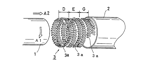
IO The friction resistance generator comprises a cylindrical
rotary member 1 which rotates in the rotation direction of A1, a
passive member 2 which is opposed to the outer peripheral surface
of the rotary member 1, and a number of rollers 3 arranged along
the rotation path A1 of the rotary member 1. The rollers 3 form
plural roller trains. Each of the rollers 3 is rotatably
supported on the inner peripheral surface of the passive member 2
by a support member 4. In Fig. 1, the rotary member 1, the
20 Passive member 2, and the rollers 3 are shown so as to be
separated in the axial direction for convenience of explanation.
Actually, however, the rotary member 1 and the passive member 2
are opposed to each other in the radial direction, and the
rollers 3 are arranged between the opposed surfaces of the rotary
member 1 and the pas s ive member 2 .
Each of the rollers 3 has a columnar shape extending in the
axial direction, and is formed so that the diameter thereof
30 decreases gradually in the axial direction from both of the ends
to the middle. Specifically, the rollers 3 are formed so as to
come into line contact with the outer peripheral surface of the
rotary member 1, and are arranged at equal intervals in the
circumferential direction of the rotary member 1. In this case,
the support member 4 for supporting both ends of the roller 3
comprises a member of low friction such as a bearing.
. . CA 02293075 1999-12-23
Also, the friction resistance generator is provided with a
plurality of roller train groups 3a comprising paired roller
trains, in which the rollers 3 are inclined in the opposite
direction to each other, in the axial direction of the rotary
member 1. In this case, in each roller.train group 3a, the
rollers 3 are arranged so that the rotation axis B of the roller 3
is inclined at an angle of A (or -8) whose absolute value is equal
with respect to the cross section C perpendicular to the rotation
direction of the rotary member 1.
The support member 4 comprises a pair of bearings 41
installed at both end portions 31 of the roller 3, a pair of
support frames 42 arranged at both sides of the roller 3, and a
shaft 43 both ends of which are supported on the support frames 42
as shown in Fig. 4. The roller 3 is installed rotatably to the
shaft 43 via the bearings 41. A leg portion 44 of each of the
support frames 42 is fixed to the passive member 2 by means of a
bolt 45.
Also, as shown in Fig. 5, one of the leg portions 44 is
provided with an angle adjusting mechanism 46 comprising an
arcuate elongated hole 461 so that the inclination angle 8 (or -8)
of the rotation axis of the roller 3 can be arbitrarily adjusted
by loosening the bolt 45 .
Further, as shown in Fig. 6, an end portion 431 of the shaft
43 is formed into a square shape in cross section, and is fitted
in an elongated hole 462 formed in the support frame 42 so as to be
movable vertically. Also, a spring 47 for pressing the shaft 43
upward is provided in the elongated hole 462, so that the roller 3
is urged against the passive member 2 by the spring 47. Further,
a bolt 433 is installed at each of the end portions 431 of the
shaft 43, so that the axial movement of the shaft 43 is regulated
_g_
CA 02293075 1999-12-23
by the bolts 433.
In the friction resistance generator configured as
described above, when the rotary member 1 is rotated in the
direction of A1 while a load F is applied to the passive member 2
as shown in Fig. 7, the rollers 3 rotate while being in contact
with the rotary member 1. At this time, the roller 3 rotates
while the rolling motion thereof in the direction inclined at the
angle of A (or -A) is regulated as shown in Fig. 8. Therefore, a
frictional force according to the load F in the axial direction B
is produced between the roller 3 and the rotary member 1. At this
time, the roller 3 produces sliding friction while rotating, so
that less static friction is produced even at the time of
low-speed rotation, whereby a stable resisting force can always
be provided. In this case, even if static friction is produced
at an early stage, it is transferred to dynamic friction
momentarily by the rotation of the roller 3. Also, if the load of
the rotary member 1 is released, a state in which no frictional
force is produced can be obtained.
Thus, according to the friction resistance generator of
this embodiment, the rotation axis B of the roller 3 is inclined
at the predetermined angle of 8 (or -8) with respect to the cross
section C perpendicular to the rotation direction A1 of the
rotary member 1, by which sliding friction is produced while the
roller 3 is rotated. Therefore, in the rotating motion of the
rotary member 1, an arbitrary resisting force proportional to
the load on the passive member 2 can be obtained. Moreover, by
changing this load, the resisting force of the rotary member 1
can be controlled very easily. At this time, since the sliding
friction entails the rotation of the roller 3 , static friction,
which causes the stick slip, can be made far less, so that a
_9_
CA 02293075 1999-12-23
stable frictional resistance can always be obtained. Therefore,
the friction resistance generator can be applied to a rotary
brake or the like very advantageously.
Also, according to this embodiment, since the roller 3 is
rotatably installed to the passive member 2 via the support
member 4, the roller 3 can be formed so as to rotate while being in
contact with the rotary member 1 only, so that this embodiment
can be applied to the apparatus such that the opposed surfaces of
the rotary member 1 and the passive member 2 have a curved shape.
Although the embodiment in which the rollers 3 are installed on
the inner peripheral surface of the passive member 2 has been
shown above, the configuration may be such that for example, the
rotary member is formed by an outside cylinder, and the rollers
are installed on the inside passive member. In this case,
friction is produced between the rollers and the outside rotary
member, so that the effect of cooling from the outside against
the frictional heat caused by the rollers becomes excellent.
Further, the frictional force can be controlled by changing
the angle 8, and also the braking force can be controlled by the
diameter of the roller 3 and the surface material thereof .
Also, as shown in Fig. 8, the rollers 3 in each roller train
produce frictional forces fl and f2 which are approximately
equal in the opposite direction to each other, but the axial
forces of the rotary member 1 are canceled each other. As a
result, the rotary member 1 rotates along the rotation path A1
without producing an axial positional shift. Specifically, the
rotary member 1 is configured so that it is not moved in the axial
direction by its own rotation, and can be moved in the axial
direction only by any external force which displaces the rotary
member 1 in the axial direction. In this case, the roller 3
-10-
CA 02293075 1999-12-23
attempts to roll toward the outside of the roller train, but the
configuration may be such that the inclination angle A (or -8) of
the roller 3 in each roller train is made opposite to the
embodiment so that the roller 3 attempts to roll toward the
inside of the roller train.
In the above-described embodiment, the rotary member 1 can
be moved in the axial direction (direction A2 in Fig. 1).
SPecifically, when the rotary member 1 is moved from a position
where it is in contact with the roller train group 3a in a region D
to a position where it is in contact with the roller train groups
3a in regions D and E, the frictional resistance increases.
Similarly, when the rotary member 1 is moved to a position where
it is in contact with the roller train groups 3a in regions D, E
and G, the frictional resistance increases further. Therefore,
the magnitude of the frictional force can be controlled
arbitrarily according to the movement distance of the rotary
member 1 in the direction of arrow A2 without adjusting the
angles of the rollers 3. When the frictional force is
controlled, control means (not shown) for displacing the rotary
member 1 in the axial direction is provided separately.
Figs . 9 and 10 show a second embodiment of the present
invention. This embodiment is the same as the first embodiment
except for the arrangement of the rollers 3. Therefore, the
duplicated explanation is omitted.
In the second embodiment, the rollers 3 are arranged so as to
be inclined by repeating the angles 8 and -8 alternately in the
rotation direction A1 of the rotary member 1. Thereby, in one
roller train 3b, the forces acting on one side and the other side
in the axial direction of the rotary member 1 are uniformly
produced as a whole. Therefore, the forces in the axial
- 11 -
CA 02293075 1999-12-23
direction of the rotary member 1 can be canceled each other, so
that the axial positional shift of the rotary member 1 is not
produced by the own rotation of the rotary member 1. In this
case, a plurality of roller trains 3b are provided in the axial
direction of the rotary member 1, and the rotary member 1 is moved
from a region H of the roller train 3b to a region J as in the case
of the first embodiment, by which the magnitude of the frictional
force can be controlled arbitrarily. Although the rollers 3 are
arranged in the opposite direction alternately one by one in this
embodiment, the rollers 3 may be .arranged in the opposite
direction alternately every several rollers.
Fig. 11 shows a third embodiment of the present invention.
This embodiment is the same as the first embodiment except for
the arrangement of the rollers 3. Therefore, the duplicated
explanation is omitted.
In this third embodiment, the roller train group 3a arranged
as in the case of the first embodiment is arranged continuously
along a spiral path 3c around the axis of the rotary member 1.
Thereupon, when the rotary member 1 is moved in the, axial
direction, the number of rollers 3 which are in contact with the
rotary member 1 changes, by which the magnitude of the frictional
force can be controlled arbitrarily. In this case, since the
rollers 3 are arranged continuously in a spiral form in the axial
direction of the rotary member 1, the magnitude of the frictional
force can be controlled in a stepless manner. Also, in this
embodiment, as in the case of the second embodiment, the rollers
3 can be arranged in the opposite direction alternately one by
one.
Fig. 12 shows a fourth embodiment of the present invention,
in which there is provided a generator 48 that is driven by the
- 12 -
CA 02293075 1999-12-23
rotation of the roller 3. In this case, the generator 48 is
provided on one of the support frames 42, and a rotating force is
transmitted from one of end portions 311 of the roller 3 to the
generator 48. Specifically, when the friction resistance
generator of the present invention is used for a rotary brake, -
braking energy can be utilized effectively by the generator 48.
For example, if the power of the generator 48 is stored in a
battery, it can be utilized as a power source for the relating
electronic devices . Also, since the load of the generator 4 8 is
added to the rotation of the roller 3, the braking force can be
enhanced.
Needless to say, the present invention is not limited to the
above-described embodiments. The friction resistance generator
of the present invention can be applied to not only the rotary
brake mechanism but also various types of machines such as a
clutch mechanism for a driving shaft of an automobile etc., an
automatic closing apparatus for a door, a braking mechanism for
an elevator, a shock absorbing mechanism for an automobile etc.,
and a braking mechanism for a seat belt .
Figs. 13 to 16 show a fifth embodiment of the present
invention, in which the friction resistance generator in
accordance with the present invention is configured as a seismic
isolation device for a building. In these figures, the same
reference numerals are applied to essentially the same elements
as those in the above-described embodiments.
The seismic isolation device of this embodiment comprises a
rotary member 5 formed into a hemispherical shape and a
substantially hemispherical passive member 6 opposed to the
inner surface of the rotary member 5. A number of rollers 3, each
of which is rotatably supported by a support member 4 that is the
- 13 -
CA 02293075 1999-12-23
same as that in the above-described embodiments, are arranged
between the rotary member 5 and the passive member 6. The rotary
member 5 and the passive member 6 are arranged concentrically
with each other with their convex sides facing upward.
The rotary member 5 has an inside diameter somewhat larger
than the outside diameter of the passive member 6 so as to cover
the passive member 6, and a plurality of protrusions 51
Projecting to the outside are provided at intervals in the
circumfereritial direction at the lower end part of the rotary
member 5. At the~top of the rotary member 5, a spherical
connecting portion 52, which is connected to a structure 7 on the
side of the building, is provided. The connecting portion 52 is
rotatably fitted in a bearing 71 provided on the bottom surface
of the structure 7. In this case, the connecting portion 52 may
be disposed at any position that is convenient in terms of
structure other than the top of the rotary member 5 .
The passive member 6 is formed so as to be somewhat larger
than a hemisphere, and is fixed to the ground on which the
building is disposed. A plurality of protrusions 61 are provided
at intervals in the circumferential direction at the lower end
part of the passive member 6. The protrusion 61 is connected to
the protrusion 51 of the rotary member 5 via a spring 8.
Specifically, the springs 8 configure rotation regulating means
for elastically regulating the rotation of the rotary member 5 .
The roller 3 is installed on the inside surface of the rotary
member 5 via the support member 4. When the equator line K along
the lower end of the rotary member 5 is assumed, the rollers 3 are
arranged in a range X above the equator line K along the equator
line K. In this case, the rotation axis B of the roller 3 is
arranged so as to be inclined at an angle of A (about 45°) with
- 14 -
CA 02293075 1999-12-23
respect to a longitude line Z of the rotary member 5. The roller
3 has a curved shape in which the middle portion is concave, so
that it always comes into line contact with the spherical surface
of the passive member 6.
In the seismic isolation device constructed as described
above, the springs 8 are mutually balanced, and the position of
the top of the rotary member 5 agrees with the top of the passive
member 6 in the normal state, thereby the state shown in Fig. 15
being kept. If the system is subjected to a transverse swing
caused by an earthquake or the like, the rotary member 5 turns in
the direction R opposite to the transverse swing, and the passive
member 6 is moved in the direction M together with the ground as
shown in Fig. 16. At this time, the rotary member 5 is subjected
to a frictional resistance (braking force) due to the rollers 3,
so that the swing of the structure 7 in the direction N is damped
by this frictional resistance. Also, since the movement range of
the rotary member 5 is regulated by the springs 8, the rotary
member 5 is not turned extremely, so that the rollers 3 are kept
in a state in which they are always brought into contact
effectively with the passive member 6.
Thus, according to the seismic isolation device of this
embodiment, static friction and dynamic friction do not act
intermittently, so that seismic vibrations can be damped by the
very stable braking force. Also, a complicated damping
apparatus such as a shock absorber and a damper is not used, so
that the construction can be simplified. Further, since the
opposed surfaces of the rotary member 5 and the passive member 6
are formed into a spherical shape, the rotary member 5 can be
moved in the three-dimensional direction, so that this system
can accommodate transverse vibrations in all directions .
-15-
~
. CA 02293075 1999-12-23
Since the rotary member 5 is formed so as to cover the
passive member 6 and the rollers 3 from the upside, it has a
dust-proof function, so that the system can be used even in
severe conditions other than on the floor or in the room. In this
case, the system is best suitable as a seismic isolation device
for furniture and buildings because of its simple construction.
Although the configuration in which the rollers 3 each
having a curved surface with the center being concave are
provided on the side of the rotary member 5 is shown in the
above-described embodiment, the rollers 3 each having a curved
surface with the center being convex may be provided on the side
of the passive member 6, and the rollers 3 may be brought into
contact with the inside surface of the rotary member 5 .
Also, although the plurality of springs 8 are used as the
rotation regulating means in the above-described embodiment,
the rotation regulating means may be configured by a damping
apparatus such as a shock absorber or a damper .
Further, although the example in which the friction
resistance generator in which the opposed surfaces of the rotary
member 5 and the passive member 6 are formed into a spherical
shape is used for a seismic isolation device is shown in the
above-described embodiment, the apparatus can be applied to
various types of machines as an articulated joint with braking
function.
-16-