Note: Descriptions are shown in the official language in which they were submitted.
CA 02293109 1999-12-23
I
2 Title: LIGHTER WITH A SAFETY SYSTEM
3
4 BACKGROUND OF TH INVENTION
The present invention relates to a lighter device, and more particularly to a
unique safety
6 system incorporated into the lighter. Specifically, the present invention
relates to a push button
7 safety switch which cooperates with an ignition trigger of the lighter to
allow ignition of the lighter
8 by coordinating the simultaneous deactivation of the safety and the
engagement of the trigger.
9 Current safety switches on lighters are awkward to engage. Some switches are
such that
when the switch is moved to the "safety off' position to allow the operator to
ignite the lighter, by
11 pulling a trigger mechanism, the safety remains in the "safety off"
position allowing for subsequent
12 unprotected ignition attempts. This may be a dangerous condition if the
lighter falls into the hands
13 of a child. Since such safety switches do not automatically re-engage to
the "safety on" position, a
14 child could pull the ignition trigger and ignite the lighter.
1 S Additionally, other prior art devices include U.S. Patent Nos. 5,865,614;
5,697,775; and
I 6 5,496,1 G9.
17 U.S. Patent No. 5,697,775 illustrates and teaches a safety switch which
requires the operator
18 to press the safety switch downwardly while pulling the trigger rearwardly.
While the device is
19 difficult for children to use, it is an awkward operation for even adults
to use. Further one
embodiment of the device of U.S. Patent No. 5,697,775 houses the safety switch
in the trigger
21 section of the lighter housing.
CA 02293109 1999-12-23
1 The present invention places the safety switch on top of the lighter housing
outside and away
2 from the trigger section. The present invention allows for the simultaneous
engagement of the safety
3 switch by urging the switch forward to the "safety off' position while the
ignition trigger is pulled
4 rearwardly. This requires a level of coordination not normally obtained by
children, but still simple
S enough for adults. Thus, the operator simultaneously pulls the ignition
trigger rearwardly with the
6 forefinger of one hand and urges the safety switch forward with the thumb of
the same hand. The
7 lighter then lights. The safety switch may then be released and the flame
continues. After the trigger
8 is released, the flame is extinguished. The safety switch automatically
returns to the "safety on"
9 position preventing accidental ignition.
11 SUMMARY OF THE INVENTION
12 The present invention is a lighter having an ignition trigger operable
within the lighter
13 housing. A safety switch operable within the same housing but away from the
trigger section,
14 includes a pivotable safety pin movable from a first "safety on" position
to a second "safety off'
I 5 position. The pivot pin has an engagement foot on the distal end of the
pin which blocks the ignition
16 trigger from being pulled or activated to initiate ignition of the lighter.
The engagement foot
17 engages a slot in the trigger. A narrow leg extends upwardly from the
engagement foot and is
18 provided with a generally central opening to receive a positioning pillar
which acts as the pivot
19 point. When the tap of the pin is urged forwardly along a generally
longitudinal axis of the lighter
while simultaneously with the pulling of the trigger oppositely along the same
general longitudinal
21 axis of the lighter, the narrow leg of the safety pin pivots and the foot
disengages from the trifler
22 slot. The trigger then may be pulled sufficiently to initiate lighter
ignition. Thus, the simultaneous
-2-
CA 02293109 1999-12-23
1 forward movement of the pin from "safety on" to "safety ofP' with the
rearward pulling of the trigger
2 along the same general longitudinal axis of the lighter activates the
lighter. It is the arrangement and
3 movement of the elements of the present invention which results in a safety
system requiring a level
4 of hand coordination not normally developed in a child and yet not so
awkward as to inconvenience
adults. Once the trigger is released, the pin automatically returns to the
"safety on" position.
6
BRIEF DESCRIPTION OF THE D AWINOS
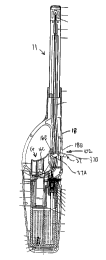
8 Fig. 1 A is a cross-sectional view of a prior art lighter, with the trigger
not pulled.
9 Fig. 1B is a cross-sectional view of a prior art lighter, with the trigger
pulled.
Fig. 1 C is a bottom view of a prior art lighter.
11 Fig. 2A is a cross-sectional view of the safety lighter of the present
invention, with the trigger
12 not pulled.
13 Fig. 2B is a cross-sectional view of the safety lighter of the present
invention, with the trigger
14 pulled rearwardly and the safety pin urged forwardly.
Fig. 2C is a bottom view of the safety lighter of the present invention.
16 Fig. 3 is an exploded perspective view of the components of the safety
system of the present
17 invention.
18 Fig. 4 is a perspective view of the components of the safety system of the
present invention
19 in the "safety on" position.
Fig. 4A is a detailed perspective view of the components of the safety system
of the present
1 invention in the "safety on" position.
-3-
CA 02293109 1999-12-23
1 Fig. S is a perspective view of the components of the safety system of the
present invention
2 in the "safety off' position.
3 Fig. 6 is a perspective view of the components of the safety system of the
present invention
4 in a position where the safety is "off' and the trigger is urged rearwardly.
S
6 DETAILED DESCRIPTION OF THE PREFERRFn FMRnnmrFNT
7 Figs. 1 A, 1 B and 1 C illustrate a typical prior art lighter 10 having an
ignition trigger 16
8 operable within the lighter housing 18. The operation of such lighters is
well-known in the art. The
9 operator holds the lighter 10 by one hand and pulls or presses the trigger
16 with his or her finger.
Movement of trigger 16 pushes the gas lever 19 downwardly which in turn
elevates nozzle A to
11 release gas. Gas is driven to upper end nozzle B through gas pipe 23. At
the time the trigger 16 is
12 depressed, piezoelectric actuator 21 is vibrated to emit an electric charge
which is transmitted to
13 conductive pipe 25 through its conducting wire.
14 Since pipe 25 is a conductor, an electric charge is conducted to pipe end
25A.
Simultaneously, another electric circuit transmits the electric charge to
nozzle B through the contact
16 of the bottom of piezoelectric actuator 21 A and ground wire 22. Because
nozzle B is a conductor,
17 electric charge is conducted to sparkling spring 31. When meeting a spark,
the gas lights a flame
18 100.
19 The present invention is shown in detail in Figs. 2A, 2B and 2C. The safety
system 102 is
built into the lighter 11 without any significant modifications to the
existing prior art lighter 10. The
safety s~:~t~h is o"tside the trigger section and requires a forward pressure
on the switch head or top
22 and a rearward depression of the trigger to activate the lighter 11.
-4-
CA 02293109 1999-12-23
I The lighter housing 18 is designed to include an opening 18B on the top side
of the lighter
2 11 for pivotal switch safety pin 37 whereas trigger 16 on the underside of
the lighter in the trigger
3 section is designed with a slanted slot 16B and a top edge 16A (Fig. 3).
Additionally, a torsional
4 switch spring 38 is designed for inclusion in the present invention to urge
the safety pin 37 to the
"safety on" position.
6 In Figs. 3-6, most of the lighter parts are not shown so that the safety
system 102 of the
7 present invention may be more clearly observed. As may be seen in Figs. 3-6,
switch safety pin 37,
8 switch spring 38, and trigger 16 are assembled in housing 18. Pivotal switch
safety pin 37 is urged
9 rearward to the "safety on" position under the spring action of spring 38.
Top end 38A of the spring
comes in contact with inner bottom part 18E of housing 18 and lower spring end
38B applies
11 torsional farce against the front side 37D of narrow leg 37E of pin 37.
12 In this first position trigger top edge 16A and slanted slot 16B come in
contact with hook 37F
13 of engagement foot 37A. It is, therefore, not possible to press the trigger
16 rearwardly to ignite the
14 lighter 11 because edge 16A of trigger 16 is blocked from rearward movement
by engagement foot
37A. The sharp hook 37F engages into the slanted slot 16B to further secure
the trigger from
16 movement. Piezoelectric actuator 21 cannot be actuated nor can the gas
lever 19 be raised to release
17 gas. The lighter cannot be ignited under this first "safety on" position.
18 The top 37B of the pin 37 pivots forward as pin 37 rotates about the
positioning pillar 18A
19 which extends through a generally, central pivot opening 37C in pin 37. As
may be seen in Fig. 3
the pillar 18 is generally cylindrical upstanding protrusion attached to a
side wall of the housing 18.
21 The pillar is aligned i_n h~nsing opening 18B. Opening 18B has a front edge
1 RD and a rear edge
22 18C. As the pin 37 is urged forward its rotational movement is stopped by
edge 18B. As will be
-5-
CA 02293109 1999-12-23
1 seen below when the pin 37 is released, it springs back to its first
position (Fig. 4) by the action of
2 spring 38. Pin 37 is stopped in its return rotation by edge 18D.
3 Fig. 4A shows in detail the position of spring ends 38A and 38B withing the
housing 18. The
4 top end 38A and 38B extend the inner side 18E of housing 18 and lower end
38B urges against the
side 37D of pin 37. The spring is held securely in place by wrapping around
pillar 18A as the pillar
6 body passes through the inner coil of the spring.
7 As shown in Fig. S, a top 37B on the proximal end of pivotal pin 37 must be
pressed forward
8 parallel the longitudinal axis of the lighter 11 by the operator's thumb at
the same time the fingers
9 of the same hand rearwardly depress the trigger 16 parallel the longitudinal
axis L . Foot 37A and
I0 hook 37F move rearward to disengage top edge 16A and slanted slot 16B of
trigger 16. A narrow
1 I leg portion 37E of pin 37 pivots rearward bout positioning pillar 18 in
housing 18. However, the
12 spring action of spring 18 seeks to urge the pivot pin 37 back to the
"safety on" position. The
13 pivoting of the leg 37E, and foot 37A, and hook 37F, out of engagement with
edge 16A and slanted
14 slot 16B allows the trigger 16 to be depressed and the lighter 1 I to
ignite. This is a second position.
I 5 This simultaneous operation of the safety pin 37 and trigger 16 requires
more hand coordination than
16 is normally achieved by a child.
17 As shown in Fig. 6, when top 37B is released, leg 37E cannot pivot back
while the trigger
18 16 is rearwardly depressed. Foot 37A cannot engage slanted slot 16B. As
trigger 16 is urged
l 9 rearward by the forefinger, simultaneously gas lever 19 is raised by the
rearward motion of trigger
20 16 to release gas. Also, the engaging of trigger 16 activates the piezo
effect of piezoelectric actuator
21 21 to discharge electric charge. The gas, as released, will meet with the
spark produced to light a
22 flame. This is the ignition condition in operation. Release of the
forefinger after use will allow the
-6-
CA 02293109 1999-12-23
1 trigger to return to offposition, and pin 37 will automatically pivot back
into the "safety on" position
2 as shown in Fig. 4 and 4A.
3 Although the invention has been described with reference to a specific
embodiment, this
4 description is not meant to be construed in a limiting sense. On the
contrary, various modifications
S of the disclosed embodiments will become apparent to those skilled in the
art upon reference to the
6 description of the invention. It is therefore contemplated that the appended
claims will cover such
7 modifications, alternatives, and equivalents that fall within the true
spirit and scope of the invention.
8
_7_